

Page 1

V. 1.1.17
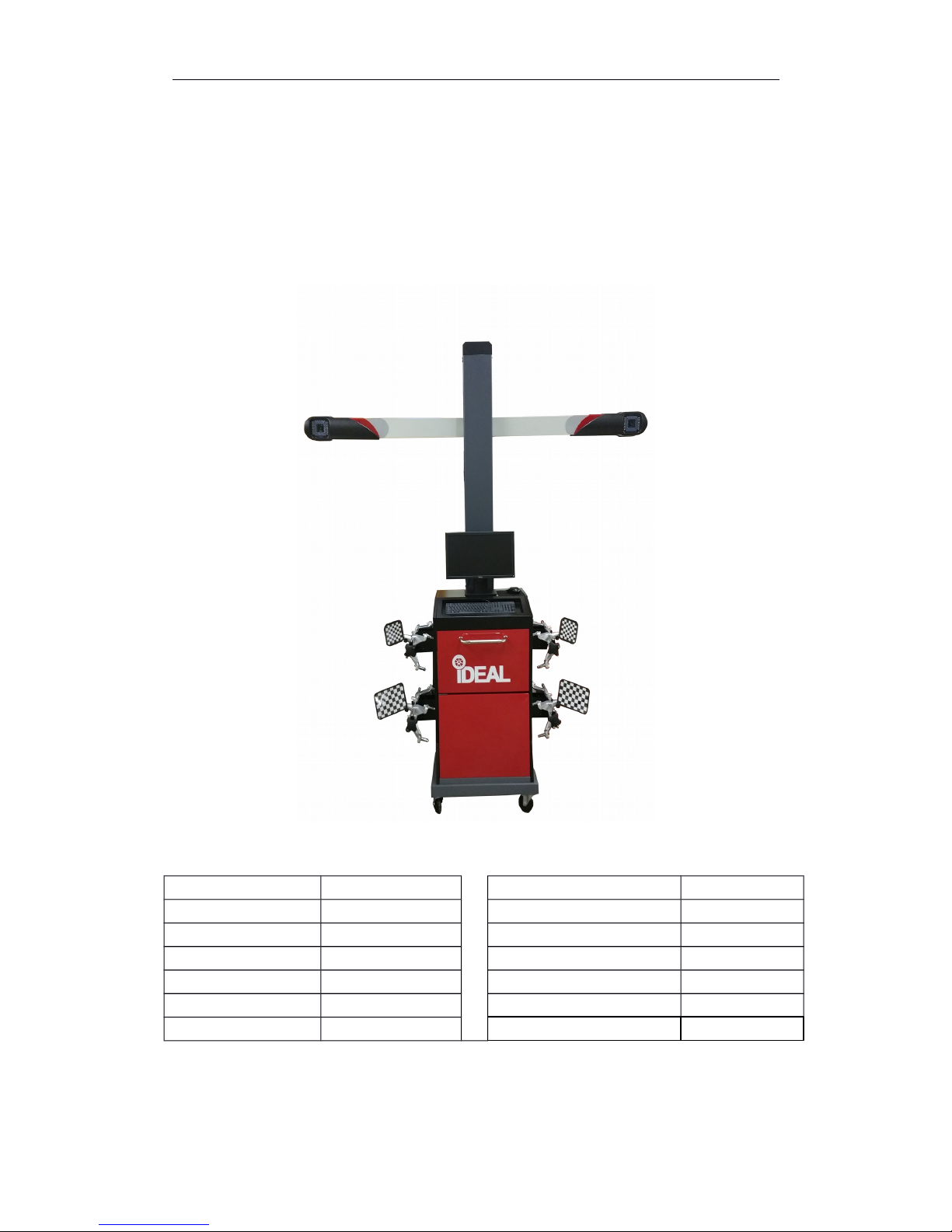
3D Wheel Aligner
Manual
IWA-60-1500-K
Page 2

IDEAL 60-1500 Wheel Aligner Manual
Table of Contents
———————————————————————————————————————-
I. Introduction...........................................................................................................3
1.1 Warning..................................................................................................................3
1.2 Safety warning.......................................................................................................3
II. Getting Started......................................................................................................5
2.1 Equipment transport conditions.............................................................................5
Uncrating Instructions..................................................................................................5
2.2 Smart LED board...................................................................................................6
2.3 Equipment and Servicing.......................................................................................8
1. Check List.........................................................................................................8
2. Camera Care....................................................................................................9
3. Target Care.......................................................................................................9
III. Installation Guide................................................................................................10
3.1 Installation Dimensions........................................................................................10
3.1.1 Camera Beam Position..............................................................................10
3.1.2 Level Lift.....................................................................................................11
3.2 Positioning............................................................................................................13
3.3 Installing wheel clamps and target.......................................................................14
3.3.1 Installing wheel clamps..............................................................................14
3.3.2 Fixing targets.............................................................................................14
3.4 Installing/Removing brake depressor..................................................................15
3.5 Installing/Removing steering wheel holder..........................................................15
IV. Software..............................................................................................................16
4.1 Opening/Closing Alignment software...................................................................16
4.2 Hot keys...............................................................................................................17
4.3 Visual Check........................................................................................................18
4.4 Standard Measurement.......................................................................................18
4.5 Quick Measurement.............................................................................................37
4.6 Aligner Management............................................................................................40
V.Technical data.............................................................................................................45
5.1 Measuring Range.................................................................................................45
5.2 Power supply unit.................................................................................................45
Appendix I . Troubleshooting.............................................................................................46
2
Page 3

IDEAL 60-1500 Wheel Aligner Manual
I.
Introduction
The purpose of this manual is to provide safe and practical instructions for
operation and maintenance of the imaging wheel aligner.
1.1 Warning
This aligner is designed for INDOOR USE ONLY. Exposure to damp or wet
locations can cause damage to the aligner’s components or injury to the
user and will void warranty.
The computer in this aligner is capable of connecting to a network and/or the
Internet. This functionality is only for use when receiving support for the
aligner. The computer should be connected to the Internet if possible,
however it should never be used for recreational or administrative purposes.
Any malfunctions due to unauthorized software, malware, viruses, or similar
web based threats are not
Do not plug in the cabinet power cord until all connections have
been verified. Damage or injury can result.
1.2 Safety Warning
This imaging aligner is intended for use by properly trained automotive
technicians. The safety messages presented in this section and throughout
the manual are reminders to exercise extreme care when performing wheel
alignments with this product.
There are many variations in procedure, technique, tools, and parts for
servicing vehicles. The manufacturer cannot possibly anticipate or provide
advice or safety messages to cover every situation. It is the automotive
technician’s responsibility to be knowledgeable about the vehicle to be
aligned. It is essential to use proper servicing methods. Always perform wheel
alignments in an appropriate manner, that does not endanger operator safety,
the safety of others in the work area, the equipment, or the vehicle being
serviced.
Read this manual carefully before powering up the aligner. Save this manual,
and all supplied illustrative material, in a folder near the aligner cabinet, where
it is readily accessible for reference by operators.
3
Page 4

IDEAL 60-1500 Wheel Aligner Manual
The technical documentation supplied is considered an integral part of this
equipment; in the event of sale all relative documentation must remain with
the system.
This manual is only valid for the equipment model and serial number indicated
on the nameplate of the included aligner. The nameplate is attached to the
back of the cabinet.
WARNING!
Any modifications to this aligner may cause serious injury or
damage to the aligner. The manufacturer and distributors are not
responsible for any injury caused by improper use, abuse, or unauthorized
repair.
4
Page 5

IDEAL 60-1500 Wheel Aligner Manual
II.
Getting Started
2.1 Equipment Transport Conditions
The aligner must be shipped in its original packing and stowed in the position
indicated on the outside.
To avoid damage, never place other items on top of the packaging.
Handling of the crated aligner must be performed only with an appropriate
lifting device such as a forklift or pallet jack.
Only personnel who are experienced and qualified in freight handling
procedures should handle any transportation or moving of the crated aligner.
Inspect for any damage to the crate and notify your local distributor (and/or
freight company) immediately if any damage is observed.
Uncrating Instructions:
Carefully remove packing materials. Be careful when cutting banding material
as items may loosen and fall, causing personal harm or injury.
Always wear gloves when uncrating to prevent scratches, abrasions, or cuts
due to the contact with packing materials.
Retain all packaging in case you need to return any parts for warranty or
servicing. Carefully unpack and inventory all items. Familiarize yourself with
all components before beginning set up and assembly.
5
Page 6

IDEAL 60-1500 Wheel Aligner Manual
2.2 Smart LED Board
Smart LED board includes the following features
:
Target Level Indication
LR Target LF Target RF Target RR Target
If the target is not leveled, LED lights will turn red. When all the lights turn
green and the middle two lights start to blink, the target is leveled.
Forward/Backward Moving Car Indication
Position Direction Position Direction
The left line of LED lights represents the position of the vehicle. The right line
6
Page 7

IDEAL 60-1500 Wheel Aligner Manual
of LED lights shows the direction, forward or backward, of the measured
vehicle.
Swing Caster Indication
Direction Angle Direction Angle
The left line of LED lights represents the direction of turning angle, clockwise
or counterclockwise, of the measured vehicle. The right line of LEDs show the
progress of the turning angle.
Target Blocking Indication
LR Target LF Target RF Target RR Target
When the middle two lights turn red and start to blink, the corresponding
target is blocked.
7
Page 8
IDEAL 60-1500 Wheel Aligner Manual
2.3 Equipment and Servicing
1. Check List
Standard Configuration
:
Computer 1 Wheel Clamp 4
Post 1 Wheel Stopper 2
Monitor 1 Steering Wheel Holder 1
Cabinet 1 Brake Depressor 1
Software 1 Manual 1
Printer 1 Power Cord 1
Target 1 Set of 4
8
UPS AVR 1
Page 9

IDEAL 60-1500 Wheel Aligner Manual
Warning!
Please use the original accessories provided by the manufacturer.
The manufacturer and distributors are not liable for any damage or injury
caused by improper use.
2. Camera Care
Keep hand and tools away from camera.
Warning: Keep grease away from the lenses. Do not use water, detergents,
or ammonia when cleaning the lenses. Do not use heavy pressure when
cleaning. Do not use a shop rag, they may contain particles and chemicals
that can damage the lenses.
A non-ammonia cleaner may be sprayed onto a clean, lint free cloth to gently
clean the lenses. Non-ammonia glass wipes may also be used, such as Armor
All glass wipes..
Do not spray cleaners directly onto the targets.
3. Target Care
Keep targets clean, keep hands and tools away from the surface of targets.
Check that wheel clamps and targets are firmly attached and avoid dropping
the targets.
Note: When the targets are not in use, detach the targets and
clamps. Store them on the cabinet. Do not put the target faces
downward onto any surface.
Warning: Do not use water, detergents, or ammonia when cleaning the
targets. Do not use heavy pressure when cleaning. Do not use a shop rag,
they may contain particles and chemicals that can damage the targets.
A non-ammonia cleaner may be sprayed onto a clean, lint free cloth to gently
clean the targets. Non-ammonia glass wipes may also be used, such as
Armor All glass wipes.
Do not spray cleaners directly onto the targets.
9
Page 10
IDEAL 60-1500 Wheel Aligner Manual
III.
Installation Guide
3.1 Installation Dimensions
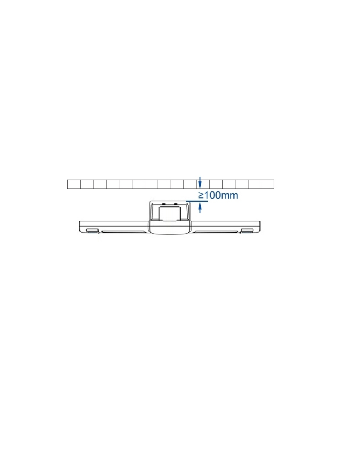
3.1.1 Camera Beam Position >100mm (4 Inches)
Diagram: Distance between post and wall
10
Page 11

IDEAL 60-1500 Wheel Aligner Manual
Diagram: Distance between cameras to center of turn table.
(See Table on page 11)
Diagram: Offset between Camera beam and turn table
L H
1800mm / 71” 550mm / 21.5”
2000mm / 78.75” 550mm / 21.5”
2200mm / 86.5” 600mm / 23.5”
2500mm / 98.5” 600mm / 23.5”
2800mm / 110.25” 600mm / 23.5”
11
Page 12
IDEAL 60-1500 Wheel Aligner Manual
3.1.2 Lift Levelness
All eight measurement points need to be within 2mm (1/8”)
Diagram: Requirement for leveling lift.
12
Page 13

IDEAL 60-1500 Wheel Aligner Manual
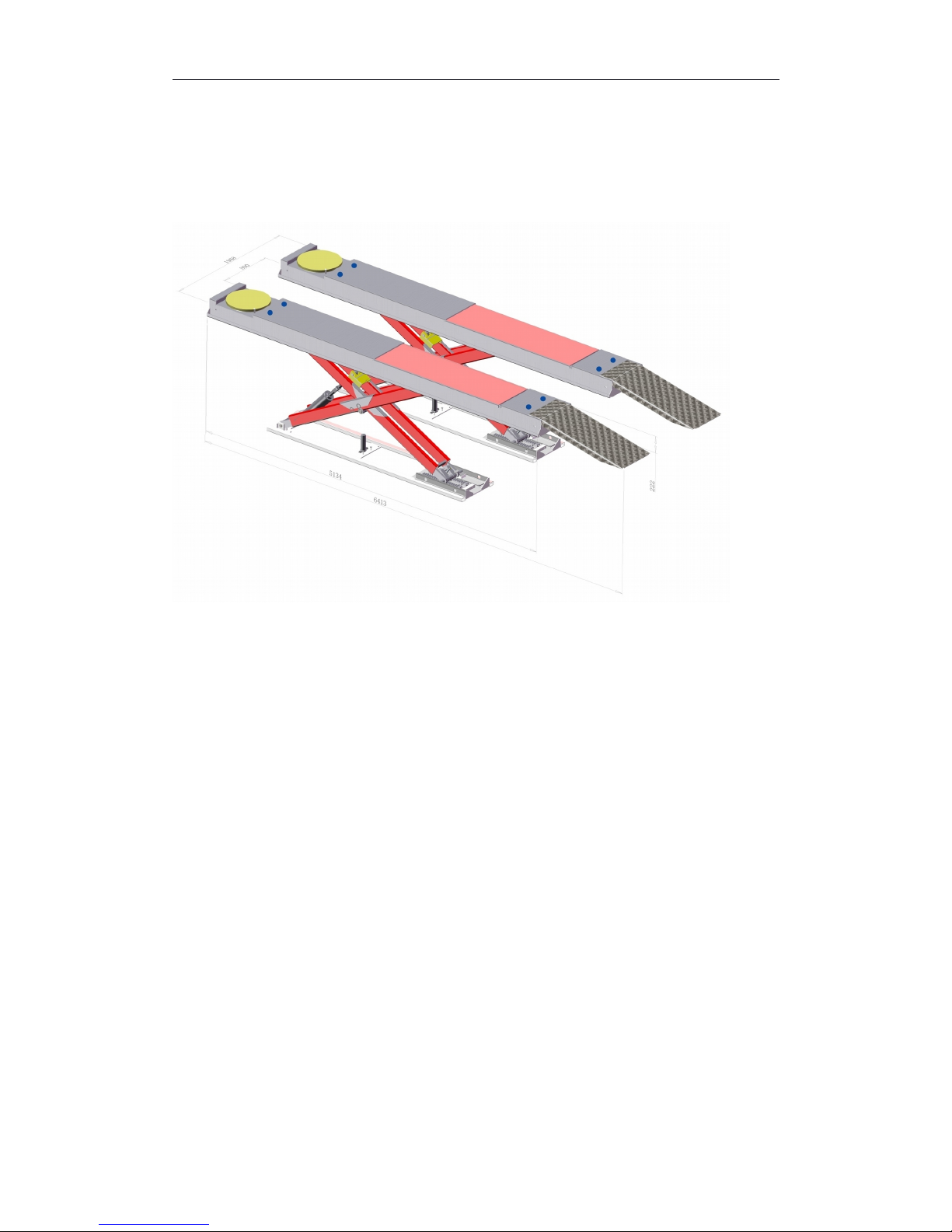
3.2 Positioning
Diagram: Positioning for fixed camera post & beam assembly.
Measure the distance between the inner sides of the runways on the lift and
find the center point. Shown as A and B. Find the center line of the lift using
these two points.
With turn table locked, at the alignment level, find the center point of the turn
table. Link the two center points of the turn table, as shown at C.
From the center line of the turn table, measure L1. Mark the first position of
the post
Mark the four point for the base of the post. Shown as E and D.
NOTE:This is also the optimum positioning for mobile units.
13
Page 14
IDEAL 60-1500 Wheel Aligner Manual
3.3 Installing Wheel Clamps and Target
3.3.1 Installing Wheel Clamps
Caution: Different wheels may have different clamping surfaces. Special
fingers may be required when used on specialty or high end wheels.
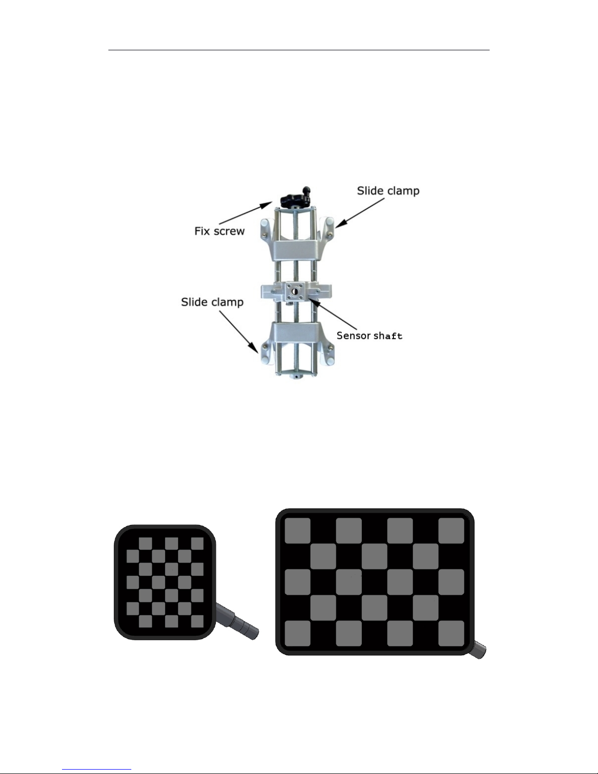
3.3.2 Attaching Targets
Always check that wheel clamps are firmly attached to wheels. Socket pins of
the measurement board may be lightly lubricated to protect the pin and
14
Page 15

IDEAL 60-1500 Wheel Aligner Manual
socket. Mount the two small targets in the front and the two larger targets in
the rear. Keep the bubble level on top.
3.4 Installing/Removing Brake Depressor
Place a cloth underneath the depressor to protect the seat if necessary. After
run out compensation, install the brake depressor for further measurements.
3.5 Installing/Removing Steering Wheel Holder.
The steering wheel holder holds the steering wheel in position and locks the
wheels.
1.
Place the steering wheel holder on the seat and press the plate against
the seat.
2.
Slide the arms downwards against the seat.
3.
Release the arms so that pressure is exerted on the steering wheel.
4.
Remove in the reverse order.
15
Page 16

IDEAL 60-1500 Wheel Aligner Manual
IV.
Software
4.1 Opening/Closing Alignment Software
Switch on power supply and push the power button to start the computer. The
computer should start the alignment software automatically. In case the
alignment software does not start, click on the icon to start the
alignment software.
If you do not see a shortcut for the alignment software, please make sure your
alignment software is properly installed; contact your local service center if
necessary.
NOTICE: If running this software on win8 or win10, please set to “Run as
administrator.”
4.2 Hot keys
This aligner uses an IBM standard keyboard, there are 12 function keys from
F1 to F12 located on the top of the keyboard. There are also specific function
keys located on the right side of the keyboard, such as “Page Up”, “Page
Down”, “Enter” “Home” and arrow directional keys. Instructions for these
function keys will be explained in following sections.
F10 - Help Version
PgUp - Previous PgDn - Next
Home - Press HOME key under any screen to go back to
software main menu screen
Warning: Do NOT directly switch off the power supply to shut down the
computer. Switching off power directly may affect proper operation of the
Operating System.
16
Page 17

IDEAL 60-1500 Wheel Aligner Manual
Diagram: Main screen
Help Previous
Next Clear Run Out
ESC –Exit Program Version Info
Management
4.3 Visual Check
Click or press F1 to enter visual check.
17
Page 18

IDEAL 60-1500 Wheel Aligner Manual
Diagram: Visual Check
Defective, replacement needed.
Warning, repair needed.
Normal, no action needed.
Next: Enter next screen.
Print: Print check table or check report as desired.
4.4 Standard Measurement
After visual check,click standard measurement to enter measurement
screen. Or click or press F2.
Standard measurement: Select customer → Select vehicle manufacturer →
18
Page 19

IDEAL 60-1500 Wheel Aligner Manual
Run out compensation → Caster Measurement → Rear Axle Measurement →
Live Caster Adjustment → Front Axle Measurement → Print.
1.
Select Enter customer info. Click “New Customer” and enter
customer info.
Diagram: Standard Measurement- Select Customer
Diagram: Enter license plate number.
2.
Select vehicle model . Select vehicle specification, Select
vehicle manufacturer, year and model.
19
Page 20

IDEAL 60-1500 Wheel Aligner Manual
Diagram: Standard Measurement - Select vehicle model.
Click next to enter manufacturer spec page.
Diagram: Standard Measurement – Manufacturer Spec
3.
Click next or to enter run out compensation.
During the alignment process, run out compensation is very important.
Skipping compensation will cause inaccurate alignment readings.
Before continuing, make sure both turn tables are locked and wheel stoppers
are in place.
20
Page 21

IMPORTANT: If the turntables are not level with the runways, you will need
to use a metal plate, board, or other material to maintain a level plane to
roll along.
Be sure to eliminate any gaps greater than 1/2” between the turntable and
added material.
The vehicle should roll smoothly without any bumps or jolts.
An inconsistent run out compensation will cause all measurements to be
inaccurate.
Use blocks or sheets of material such as wood
and metal to eliminate gaps and changes in
elevation.
Page 22

IDEAL 60-1500 Wheel Aligner Manual
Place the rear wheel stopper away from the tire, the distance may differ
depending on the size of the tire.
Follow the on screen instructions:
1)
Level Targets
2)
Install Steering Wheel Holder
22
Page 23

IDEAL 60-1500 Wheel Aligner Manual
3)
Release Brake
Diagram: Standard Measurement- Run Out Compensation
Click Next or press PgDn to continue.
Note: The top corner of the screen may show a “STOP” sign. If it appears,
keep the vehicle still. While the “STOP” sign is shown on the screen, any
movement may cause inaccurate alignment readings.
Diagram: Standard Measurement: Run Out Compensation
After first measurement, push vehicle backwards 40 degrees, software
displays “STOP” to guide the operator.
23
Page 24

IDEAL 60-1500 Wheel Aligner Manual
Diagram: Standard Measurement: Run Out Compensation
Once the bar is fully green, software reads 2nd value.
Diagram: Standard Measurement: Run Out Compensation
Push vehicle forward to its original position until the progress bar is green.
Note: Placing one of the wheel stoppers at the original position will allow the
vehicle to stop very close to the correct position. Move wheel stopper if
needed.
24
Page 25

IDEAL 60-1500 Wheel Aligner Manual
Diagram: Standard Measurement: Run Out Compensation
Push vehicle back to original position, unlock turn tables and click next to
continue.
Diagram: Standard Measurement: Run Out Compensation
Click next to finish run out compensation.
25
Page 26

IDEAL 60-1500 Wheel Aligner Manual
4.
Caster measurement .
Note: Caster measurement is disabled until full run out compensation is
completed.
Option of 10 or 20 degree can be selected in settings.
Center steering wheel first and then follow the instructions on screen. After
centering steering wheel, the screen will confirm and start caster
measurement.
Diagram: Standard Measurement – Caster
26
Page 27

IDEAL 60-1500 Wheel Aligner Manual
Diagram: Standard Measurement - Caster
Turn steering wheel left 10 or 20 degree (depending on settings) until screen
shows “Stop.” Keep steering wheel still until the 10 or 20 degree with red
background changes to “OK” with a green background.
Diagram: Standard Measurement - Caster
Turn wheel to the right until the screen shows “Stop.” Follow the same
procedure as previously indicated.
27
Page 28

IDEAL 60-1500 Wheel Aligner Manual
Diagram: Standard Measurement - Caster
Diagram: Standard Measurement - Caster
Center steering wheel after taking readings at both sides.
5.
Rear Axle
After caster measurement, the rear axle reading opens
automatically. Follow the instruction and physically center the steering wheel.
28
Page 29

IDEAL 60-1500 Wheel Aligner Manual
Diagram: Standard Measurement – Rear Axle
Diagram: Standard Measurement – Rear Axle
Rear axle screen displays rear camber, individual toe, total toe and thrust
angle. All meters have manufacturer spec and tolerance, displayed in order of:
minimum acceptable value, manufacturer value, maximum acceptable value.
29
Page 30

IDEAL 60-1500 Wheel Aligner Manual
The background of a meter indicates if the value is an acceptable reading or
not.
Red background indicates out of tolerance.
Green background indicates within acceptable
tolerance.
Blue background indicates close to
manufacturer value.
When the reading is out of manufacturer tolerance, the wheel diagram beside
the meter indicates the direction of the wheel that is out of tolerance.
Zoom In :Double clicking the live reading value can zoom in or
use arrow key on the keyboard and click enter to zoom in.
Illustration Diagram: Indicates an illustration diagram is
available.
Raised Mode: Raise the vehicle and lock camber value.
6.
Live caster adjustment
.
After rear axle reading, enter the live caster adjustment screen.
30
Page 31

IDEAL 60-1500 Wheel Aligner Manual
Diagram: Standard measurement – Live Caster
Live caster display: Camber, Caster and toe.
Note: Live caster function is an estimated value of caster.
7.
Front Axle
31
Page 32

IDEAL 60-1500 Wheel Aligner Manual
Diagram: Standard Measurement – Front Axle
Front Axle Displays: Camber, individual toe, total toe, and setback.
Toe+: Toe Adjustment
Diagram : Toe+
Enter super toe screen. The screen will instruct you to turn the steering wheel
straight ahead. Level and lock targets. Press Page Dn.
32
Page 33

IDEAL 60-1500 Wheel Aligner Manual
Diagram: Toe+
Turn steering wheel to the left adjustment position, level the target and follow
instruction on the screen.
Diagram: Toe+
Adjust left toe.
33
Page 34

IDEAL 60-1500 Wheel Aligner Manual
Diagram: Toe+
Turn steering whee to the right adjustment position and follow instruction on
screen.
Diagram: Toe+
After the measurement, the software will gather required data and compare its
data to manufacturer data, adjust the value to green or blue.
34
Page 35

IDEAL 60-1500 Wheel Aligner Manual
Diagram: Toe+
Toe Curve: VAG Adjustment
Diagram: Toe Curve
35
Page 36

IDEAL 60-1500 Wheel Aligner Manual
8.
Print
Diagram: Standard Measurement - Results
The result page displays all measurement values. Red indicates out of range,
black indicates normal. The left column is measurements before adjustment,
the center is manufacturer specs, and the right column is after adjustment.
Print: Prints a report with all readings and customer info.
Manufacturer Value: Enter the manufacturer spec page.
Compare: Compare values with previous measurements.
36
Page 37

IDEAL 60-1500 Wheel Aligner Manual
4.5 Quick Measurement
From the main screen, click or F3 to enter quick measurement.
Quick Measurement:Select Vehicle → Run Out Compensation → Front/Rear
Axle→ Print.
1.
Select Vehicle
Diagram: Quick Measurement – Select vehicle manufacturer, year, and
model.
37
Page 38

IDEAL 60-1500 Wheel Aligner Manual
Diagram: Quick Measurement – Manufacturer spec
2.
Run out compensation
.
After selecting vehicle spec, perform run out compensation and follow the on
screen instructions.
Diagram: Quick Measurement – Run Out Compensation
38
Page 39

IDEAL 60-1500 Wheel Aligner Manual
3.
Front/Rear Axle .
Note: Front/Rear Axle screen is disabled before performing a complete run
out compensation.
Diagram: Quick Measurement –Front / Real Axle
The Front/Rear Axle screen displays front and rear camber, front and rear toe,
front and rear total toe, and thrust angle.
4.
Print .
39
Page 40

IDEAL 60-1500 Wheel Aligner Manual
4.6 Aligner Management
From main screen, click or press F5 on keyboard to enter aligner
management. Use this screen to access version number, settings, and
maintenance.
Diagram: Aligner Management
Click the icon or press F1 to display software versions.
Click the icon or press F2 to changes aligner settings:
F1:Language: Use “PgDn” to confirm.
F2
:
Demo mode: Software displays each screen without connecting
cameras. In demo mode, use
Ctrl+left arrow key to demo vehicle moving forward and turning steering left or
Ctrl+right arrow for vehicle moving backward or turning steering right.
F3:Caster Sweep: 10 or 20 Degrees
F4:Measurement Mode
40
Page 41

IDEAL 60-1500 Wheel Aligner Manual
Diagram: Measurement Mode
Choose Four Wheel Alignment Mode, and select “Spacial Dynamics”, then
confirm.
Diagram: Standard-Axis is turned on.
41
Page 42

IDEAL 60-1500 Wheel Aligner Manual
F5:Unit of measurement:Choose 1/60 degree or 1/100 degree.
F6: Unit of rim diameter and distance display: choose mm or inch.
F7:Toe value unit:Choose degrees, inches, or millimeters.
If millimeters or inches is selected as the toe unit, you must enter the tire
diameter before taking measurements.
F8:Value precision:Choose 0.01, 0.05 or 0.1, rounding of measurement
result.
F9:ROC, Press Ctrl+F9, and the item F9 turns blue.
Diagram: Smart-LED-Board is turned on.
F11:Lift Height Checking: Measurement Mode, Spacial Dynamics feature
should be enabled. (Not available in the USA and Canada.)
Click or F4 to use customer management.
42
Page 43

IDEAL 60-1500 Wheel Aligner Manual
Diagram: Customer Info Management
Customer names are listed on the left side of screen. Select customer name
by Up or Down arrow direction key.
Press F8 or F9 or F11 to sort customer names by specified filter.
Press F1 to add a new customer. Operators can input new customer data
under the new customer screen.
Press F2 to edit customer information.
Press F3 to delete selected customer. Press PgDn to confirm.
Press Page Down to exit customer information manager screen.
Press HOME to go back to main menu screen.
Click or F5 to set workshop info.
43
Page 44

IDEAL 60-1500 Wheel Aligner Manual
Diagram: Workshop Information
In this screen, you can customize shop info. Enter shop name, telephone
number, fax or slogan. This info will show on the printed reports.
44
Page 45

IDEAL 60-1500 Wheel Aligner Manual
V.Technical data
5.1 Measuring Range
Options Range
Total Toe(Front and Rear Axle) ±50°
Individual toe(Front Axle) ±25°
Camber(Front and Rear Axle
)
±15°
Setback ±9°
Thrust Angle ±9°
Caster ±22°
King Pin ±22°
Wheelbase 1.6-2.1m (63”-82.5”)
Track Width 1.8-4.5m (71”-177”)
5.2 Power Supply Unit
Function Specification
Power Supply(Voltage)
110V
Frequency
50/60Hz
Power
Single Phase
45
Page 46

IDEAL 60-1500 Wheel Aligner Manual
Appendix I . Troubleshooting
Description Remedy
Computer does
not start.
Check if power cable is firmly connected, and if the
computer switch light is on.
Check the power strip is working properly.
Check fuses in cabinet.
Check power cable.
Check if power cable has output voltage.
Contact local authorized service center.
No display on
monitor.
Check if monitor is switched on.
Check power cable.
Check if display cable is connected.
Contact local authorized service center.
Computer shuts
off due to power
surge. After
restart,
alignment
software does
not start.
After a power surge, computer software may become
corrupted. Use backup software if available, to restore to a
previous working point. If a reload of the OS is needed,
contact a local authorized service center.
Screen shows a
black screen in
alignment
software and
does not close.
1. Check on screen if the target has color lines, or if the
target is in the measuring range. Adjust the target position
if needed.
2. If the target does not have color lines, but both targets
are in range, both targets maybe overlapping, or blocked.
3. If the target does not have color lines, but both targets
are in range, with no blocking, targets may be dirty. Clean
targets with care. (See Pages 9-10)
4. Cannot see target clearly, but red LEDs beside the
camera are flashing. Use a cellphone camera to check if
the LEDs are lighting up. Use the front camera, as the
rear camera of some phones have a special filter. Check
the power adapter for the correct output voltage.
45
Page 47

IDEAL 60-1500 Wheel Aligner Manual
5. No target seen on the screen, exit software and rerun
alignment software.
Contact local authorized service center if needed.
After runout
compensation,
camber or toe
value is too
high.
If measurement is interrupted during the measurement,
redo the run out compensation and check value.
Contact local authorized service center if needed
Windows starts,
but alignment
software does
not start
1.
HASP key not found:
No software key is found on the computer
Software key is plugged in but no red light on it. Check
that the driver is properly installed.
If the driver is not installed properly, download
software key driver from HASP.com
。
Contact local authorized service center if needed.
Camera screen
shows white?
Reconnect USB cable from camera to computer first. If
this does not solve the problem, check the connection
from computer to camera. Check cable.
Contact local authorized service center if needed.
For support, contact:
Northwest Equipment
877-349-2327
406-755-0805
47
Page 48

Mar 2016
LIMITED WARRANTY
Structural Warranty:
The following parts and structural components carry a five year warranty:
Columns Arms Uprights Swivel Pins
Legs Carriages Overhead Beam
Tracks Cross Rails Top Rail Beam
Limited One-Year Warranty:
Tuxedo Distributors, LLC (iDEAL) offers a limited one-year warranty to the original purchaser of Lifts and Wheel Service
equipment in the United States and Canada. Tuxedo will replace, without charge, any part found defective in materials or
workmanship under normal use, for a period of one year after purchase. The purchaser is responsible for all shipping
charges. This warranty does not apply to equipment that has been improperly installed or altered or that has not been
operated or maintained according to specifications.
Other Limitations:
This warranty does not cover:
1. Parts needed for normal maintenance
2. Wear parts, including but not limited to cables, slider blocks, chains, rubber pads and pulleys
3. Replacement of lift and tire changer cylinders after the first 30 days. A seal kit and installation instructions will be
sent for repairs thereafter.
4. On-site labor
Upon receipt, the customer must visually inspect the equipment for any potential freight damage before signing clear on
the shipping receipt. Freight damage is not considered a warranty issue and therefore must be noted for any potential
recovery with the shipping company.
The customer is required to notify Tuxedo of any missing parts within 72 hours. Timely notification must be received to be
covered under warranty.
Tuxedo will replace any defective part under warranty at no charge as soon as such parts become available from the
manufacturer. No guarantee is given as to the immediate availability of replacement parts.
Tuxedo reserves the right to make improvements and/or design changes to its lifts without any obligation to previously
sold, assembled or fabricated equipment.
There is no other express warranty on the Tuxedo lifts and this warranty is exclusive of and in lieu of all other warranties,
expressed or implied, including all warranties of merchantability and fitness for a particular purpose.
To the fullest extent allowed by law, Tuxedo shall not be liable for loss of use, cost of cover, lost profits, inconvenience,
lost time, commercial loss or other incidental or consequential damages.
This Limited Warranty is granted to the original purchaser only and is not transferable or assignable.
Some states do not allow exclusion or limitation of consequential damages or how long an implied warranty lasts,
so the above limitations and exclusions may not apply. This warranty gives you specific legal rights and you may
have other rights, which may vary from state to state.
1905 N Main St Suite C, Cleburne, TX 76033
Ph 817-558-9337 / Fax 817-558-9740
 Loading...