


GENERAL
Table 1 - General Data
Gas supply 2H-G20-20mbar
Gas Supply Connection Rc1/2 (1/2" BSP Female)
Injector size Stereomatic 5.6mm dia.
Flow Connection Central Heating 22mm copper compression
Return Connection Central Heating 22mm copper compression
Flue Terminal Diameter mm (in) 100 (4)
2
Maximum Working Pressure (Sealed Systems) bar (lb/in
Electrical Supply / Power consumption 230 V ~ 50 Hz. / 148 W
Fuse Rating External : 3A Internal : T3.15A L 250V
Water content Central Heating litre (gal) 2.0 (0.44)
Packaged Weight kg (lb) 47 (103)
Maximum Installation Weight kg (lb) 40 (88)
Boiler Casing Size Height mm (in) 687 (27)
Width mm (in) 390 (15 3/8)
Depth mm (in) 278 (11)
Table 2 - Performance Data
) 2.65 (38.5)
Boiler Size Max Min
Boiler input 'Q' = Nett CV kW 24.4 9.1
Btu/h 83 300 31 000
Gross CV kW 27.1 10.1
Btu/h 92 500 34 400
Boiler output 'P' = Gas consumption l/s (cu.ft/h) 0.70 (89.0) 0.26 (33.2)
70 °C Mean water kW 23.4 8.8
temperature Btu/h 80,000 30,000
40 °C Mean water kW 25.1 9.6
temperature Btu/h 85 700 32 800
Seasonal efficiency (SEDBUK) * Band A [90.2]%
NOx classification Class 4
* The value is used in the UK Government's Standard Assessment Procedure (SAP) for energy rating of dwellings. The test data from
which it has been calculated have been certified by a notified body.
Gas consumption is calculated using a
Note.
calorific value of 38.7 MJ/m3 (1038 Btu/ft3)
gross or 34.9 MJ/m3 (935 Btu/ft3) nett
To obtain the gas consumption at a different
calorific value:
a. For l/s- divide the gross heat input (kW) by
the gross C.V. of the gas (MJ/m
3
b. For ft
/h - divide the gross heat input (Btu/
3
)
h) by the gross C.V. of the gas (Btu/ft3)
Key to symbols
GB = United Kingdom IE = Ireland (Countries of destination)
PMS = Maximum operating pressure of water
C
13 C33 C53
= A room sealed appliance designed for connection via ducts to a
horizontal or vertical terminal, which admits fresh air to the burner
and discharges the products of combustion to the outside through
orifices which, in this case, are concentric. The fan is up stream of
the combustion chamber.
= An appliance designed for use on 2nd Family gas, Group H only.
I
2H
CAUTION.
To avoid the possibility of injury during the installation, servicing or cleaning of
this appliance care should be taken when handling edges of sheet steel components.
2
icos system -
Installation and Servicing

GENERAL
icos system m3080
Natural Gas only
G.C. Appliance No. 41 391 52
PI No. 0063BM9802
Destination Country: GB, IE
CONTENTS
Air Supply ....................................................................... 7
Boiler Clearances ......................................................... 6
Boiler Interlocks............................................................ 8
Boiler Exploded Diagram ................................... 10 & 11
Condensate Drain ................................................ 8 & 21
Electrical Connections ............................................... 23
Electrical Supply ........................................................... 8
Extension Ducts - Fitting .............................................17
Fault Finding ........................................................... 45-48
Flow Wiring Diagram ..................................................26
Flue Fitting .................................................................... 15
Flue Installation ............................................................. 7
Gas Safety Regulations ................................................ 5
Gas Supply ..................................................................... 7
Installation .............................................................. 11-29
Mandatory Requirements....................................... 5-10
Pump .......................................................................... 42
Servicing ................................................................ 30-44
Short List of Parts....................................................... 49
Thermostatic Radiator valves ..................................... 8
Water and Systems ................................................ 7-10
Water Connections ..................................................... 20
Water Treatment ......................................................... 10
Wiring Diagrams ................................................... 23-26
For GB, to comply with Building Regulations Part L1 (Part J in Scotland) the boiler should be fitted in accordance with the
manufacturer's instructions. Self-certification that the boiler has been installed to comply with Building Regulations can be
demonstrated by completing and signing the Benchmark log book.
BENCHMARK LOG BOOK DETAILS
Boiler Page
Make and model .......................................................3
Appliance serial no. on data badge ....................... 11
SEDBUK No. % ......................................................... 2
Controls
Time and temperature control to heating ............. 24
Time and temperature control to hot water .......... 24
Heating zone valves .............................................. n/a
TRV's .........................................................................8
Auto bypass ..............................................................8
Boiler interlock ..........................................................8
For all boilers
Flushing to BS.7593 .............................................. 10
Inhibitor .................................................................. 10
Central heating mode
Heat input ................................................ to be calculated
Burner operating pressure...... measure and record
Central heating flow temp. ...... measure and record
Central heating return temp. ... measure and record
For combination boilers only
Scale reducer ......................................................... n/a
Hot water mode
Heat input ............................................................... n/a
Max. operating burner pressure .............................. n/a
Max. operating water pressure .............................n/a
Cold water inlet temp ............................................n/a
Hot water outlet temp. ........................................... n/a
Water flow rate at max. setting ..............................n/a
For condensing boilers only
Condensate drain .................................................. 21
For all boilers:
For assistance see Technical Helpline on the back page
complete, sign & hand over to customer
Page
NOTE TO THE INSTALLER:
LEAVE THESE
INSTRUCTIONS ADJACENT TO THE GAS METER.
ALSO COMPLETE THE BENCHMARK LOG BOOK
AND GIVE THIS TO THE CUSTOMER.
icos system -
Installation and Servicing
3

GENERAL
INTRODUCTION
The icos system m3080 is a cast aluminium wall mounted,
full sequence, automatic spark ignition, low water content,
fanned flue, high efficiency, condensing system gas boiler.
Due to the high efficiency of the boiler a plume of water
Note.
vapour will form at the terminal during operation.
The output is fully modulating with a range of:
8.8 to 23.4 kW (30,000 to 80,000 Btu/h)
The boiler is supplied fully assembled with circulating pump,
pressure gauge, safety valve and expansion vessel.
Variable temperature control is fitted on the user control.
The boiler casing is of white painted coated mild steel with
the user controls capable of being mounted remotely from the
boiler if the option is required.
The heat exchanger is of cast aluminium.
The boiler is suitable for connection to fully pumped, sealed
water systems ONLY.
Adequate arrangements for completely draining the system
by provision of drain cocks MUST be provided in the
installation pipework.
Pipework from the boiler is routed downwards as standard, but
may be routed upwards behind the boiler using the stand-off
frame (supplied in a separate kit).
OPERATION
When there is a demand for heat, the heating system is
supplied at the selected temperature of between 30
Refer also to Frame 1 - 'Boiler Water Circuit Diagram'
The boiler features a comprehensive diagnostic system which
gives detailed information on the boiler status when operating,
and performance of key components to aid commissioning and
fault finding.
o
C and 82oC.
1
BOILER WATER CIRCUIT DIAGRAM
Fan
Sump
Condensate
'S' trap
Expansion
vessel
Burner
Automatic
air vent
Heat
exchanger
Gas valve
Pump
Water
pressure
gauge
Flow
Gas
Return
Condensate drain
4
Safety
relief valve
Discharge pipe
icos system -
Ecl 2532
Installation and Servicing

GENERAL
OPTIONAL EXTRA KITS
! Flue Extension Ducts (1000mm long, up to 6m ) .
! Flue Finishing Kit
o
! 90
Elbow Kit (Maximum 4 elbows / installation).
! 45o Elbow Kit (Maximum 4 elbows / installation).
! Powered Vertical Flue Kit (to a maximum primary flue
length of 8m + a maximum secondary flue length of 6m)
! Roof Flue Kit (to a maximum of 8m).
! Twin flueing Kit (to a maximum of 46m combined total of
flue and air ducts)
! Remote User Controls Kit.
! Boiler Stand-off Kit.
! Siphon Kit.
! Valve Cover Kit.
SAFETY
Current Gas Safety (Installation & Use) Regulations or rules
in force.
The appliance is suitable only for installation in GB and IE and
should be installed in accordance with the rules in force.
In GB, the installation must be carried out by a CORGI
Registered Installer. It must be carried out in accordance with
the relevant requirements of the:
• Gas Safety (Installation and Use) Regulations
• The appropriate Building Regulations either The Building
Regulations, The Building Regulations (Scotland), Building
Regulations (northern Ireland).
• The Water Fittings Regulations or Water byelaws in
Scotland.
• The Current I.E.E. Wiring Regulations.
Where no specific instructions are given, reference should be
made to the relevant British Standard Code of Practice.
In IE, the installation must be carried out by a Competent
Person and installed in accordance with the current edition of
I.S.813 "Domestic Gas Installations", the current Building
Regulations and reference should be made to the current ETCI
rules for electrical installation.
Detailed recommendations are contained in the following British
Standard Codes of Practice:
BS. 5440:1 Flues (for gas appliances of rated input not
exceeding 70 kW).
BS. 5440:2 Ventilation (for gas appliances of rated input not
exceeding 70 kW).
BS. 5449 Forced circulation hot water systems.
BS. 5546 Installation of gas hot water supplies for
domestic purposes (2nd Family Gases)
BS. 6798 Installation of gas fired hot water boilers of rated
input not exceeding 70 kW.
BS. 6891 Low pressure installation pipes.
Health & Safety Document No. 635.
The Electricity at Work Regulations, 1989.
The manufacturer’s notes must NOT be taken, in any way, as
overriding statutory obligations.
IMPORTANT. These appliances are CE certificated for safety
and performance. It is, therefore, important that no external
control devices, e.g. flue dampers, economisers etc., are
directly connected to these appliances unless covered by these
Installation and Servicing Instructions or as otherwise
recommended by Caradon Ideal Limited in writing. If in doubt
please enquire.
Any direct connection of a control device not approved by
Caradon Ideal Limited could invalidate the certification and the
normal appliance warranty. It could also infringe the Gas Safety
Regulations and the above regulations.
SAFE HANDLING OF SUBSTANCES
Care should be taken when handling the boiler insulation
panels, which can cause irritation to the skin. No asbestos,
mercury or CFCs are included in any part of the boiler or its
manufacture.
LOCATION OF BOILER
The boiler must be installed on a flat and vertical wall, capable
of adequately supporting the weight of the boiler and any
ancillary equipment.
The boiler may be fitted on a combustible wall and insulation
between the wall and the boiler is not necessary, unless
required by the local authority.
For electrical safety reasons there must be no access available
from the back of the boiler.
The boiler must not be fitted outside.
Timber Framed Buildings
If the boiler is to be fitted in a timber framed building it should
be fitted in accordance with the Institute of Gas Engineering
document IGE/UP/7:1998.
Bathroom Installations
This appliance is rated IP20.
The boiler may be installed in any room or internal space,
although particular attention is drawn to the requirements of the
current IEE (BS.7671) Wiring Regulations and, in Scotland, the
electrical provisions of the building regulations applicable in
Scotland, with respect to the installation of the boiler in a room
or internal space containing a bath or shower. For Ireland
reference should be made to the current ETCI rules for
electrical installations and I.S.813:2002.
If the appliance is to be installed in a room containing a bath or
shower then, providing water jets are not going to be used for
cleaning purposes (as in communal baths/showers), the
appliance can be installed in Zone 3, as detailed in BS.7671.
Compartment Installations
A compartment used to enclose the boiler should be designed
and constructed specially for this purpose.
An existing cupboard or compartment may be used, provided
that it is modified for the purpose.
In both cases, details of essential features of cupboard /
compartment design, including airing cupboard installation, are
to conform to the following:
! BS. 6798 (No cupboard ventilation is required - see 'Air
Supply' for details).
! The position selected for installation MUST allow adequate
space for servicing in front of the boiler.
! For the minimum clearances required for safety and
subsequent service, see the wall mounting template and
Frame 2. In addition, sufficient space may be required to
allow lifting access to the wall mounting plate.
icos system -
Installation and Servicing
5

GENERAL
2
BOILER DIMENSIONS, SERVICES & CLEARANCES
The boiler connections are made on the boiler piping frame.
Refer to Frames 20 & 21.
The following minimum clearances must be maintained for
operation and servicing.
Additional space will be required for installation, depending
upon site conditions.
Side and Rear Flue
a. Provided that the flue hole is cut accurately, e.g. with a
core drill, the flue can be installed from inside the building
all dimensions in mm (in)
where wall thicknesses do not exceed 600mm (24").
Where the space into which the boiler is going to be
installed is less than the length of flue required the flue
must be fitted from the outside.
Installation from inside ONLY
b. If a core boring tool is to be used inside the building the
space in which the boiler is to be installed must be at
least wide enough to accommodate the tool.
5 (1/4")
400 (15 3/4")
5 (1/4")
165
(6 1/2")
100 (4")
390 (15 3/8")
278 (11")
Flue
terminal
687
(27")
*
Ecl 2479
See inset A
A
CLEARANCES
Centre
line of
boiler
43
Flow
Condensate drain
112
Gas control
49
123
Return
Inset A Water Connections and Gas Connection
Front clearance
The minimum front clearance when built in to a cupboard is
1/4") from the cupboard door but 450mm (17 3/4")
5mm (
overall clearance is still required, with the cupboard door
open, to allow for servicing.
* Bottom clearance
After installation can be reduced to 5mm in an adequately
ventilated enclosed cupboard. However, 100mm must be
available for servicing.
BOILER DIMENSIONS
SIDE FLUE ONLY
Horizontal length of flue Top clearance
from centre line of boiler required (MIN.)
to outside wall Dim. A
0.5 m 160 mm (6
1.0 m 170 mm (6 11/16)
1.5 m 185 mm (7 1/4")
2.0 m 200 mm (
2.5 m 210 mm (8 1/4")
3.0 m 225 mm (8 7/8")
3.5 m 265 mm (9 1/4")
3.5 m 250 mm (10
4.5 m 260 mm (10 1/4")
5.0 m 275 mm (10 13/16")
5.5 m 290 mm (11 3/8")
6.0 m 300 mm (11
REAR FLUE ONLY
MIN. Top clearance required = 145 mm (5 3/
4")
5/16")
7 7/8")
5/8")
13/16")
6
icos system -
Installation and Servicing

GENERAL
GAS SUPPLY
The local gas supplier should be consulted, at the installation
planning stage, in order to establish the availability of an
adequate supply of gas. An existing service pipe must NOT be
used without prior consultation with the local gas supplier.
The boiler MUST be installed on a gas supply with a governed
meter only.
A gas meter can only be connected by the local gas supplier or
by a CORGI registered engineer. In IE by a Competent Person.
An existing meter should be checked, preferably by the gas
supplier, to ensure that the meter is adequate to deal with the
rate of gas supply required.
N.B.The principle of the 1:1 gas valve ensures that the icos
system is able to deliver its full output at inlet pressures
well below those required by BS. 6891.
IMPORTANT.
Installation pipes MUST be fitted in accordance with BS.6891.
In IE refer to I.S.813:2002. Pipework from the meter to the
boiler MUST be of an adequate size, i.e. no longer than 20m
and not less than 15mm O.D.
The complete installation MUST be tested for gas soundness
and purged as described in the above code.
FLUE INSTALLATION
Pluming will occur at the terminal, so where possible, terminal
positions where this could cause a nuisance should be avoided.
The flue must be installed in accordance with the
recommendations of BS.5440-1:2000. In IE refer to
I.S.813:2002.
The following notes are intended for general guidance:
1. The boiler MUST be installed so that the terminal is
exposed to external air.
2. It is important that the position of the terminal allows the
free passage of air across it at all times.
Table 3 - Balanced Flue Terminal Position
Terminal Position
1. Directly below or alongside an
opening window, air brick or other
ventilation opening 300 mm (12")
2. Below guttering, drain pipes or soil
pipes 75 mm ( 3")
3. Below eaves 200 mm ( 8")
4. Below balconies or a car port roof 200 mm ( 8")
5. From vertical drain pipes or soil pipes 150 mm ( 6")
6. From an internal or external corner or
to a boundary alongside the terminal 300 mm ( 12")
7. Above adjacent ground, roof or
balcony level 300 mm (12")
8. From a surface or a boundary
facing the terminal 600 mm (24")
9. From a terminal facing a terminal 1200 mm (48")
10.From an opening in a car port
(e.g. door or window) into dwelling 1200 mm (48")
11. Vertically from a terminal on the
same wall 1500 mm (60")
12.Horizontally from a terminal on the wall 300 mm (12")
Minimum Spacing
3. Minimum acceptable spacing from the terminal to
obstructions and ventilation openings are specified in
Table 3.
4. Where the lowest part of the terminal is fitted less than 2m
(6'6") above a balcony, above ground or above a flat roof to
which people have access then the terminal MUST be
protected by a purpose designed guard.
Terminal guards are available from boiler suppliers.
(ask for TFC flue guard model no. K6 - round, plastic
coated). In case of difficulty contact:
Grasslin (UK) Ltd., Tower House, Vale Rise, Tonbridge,
Kent TN9 1TB
Tel: +44 (0) 1732 359 888. Fax: +44 (0) 1732 354 445
www.tfc-group.co.uk
Ensure that the guard is fitted centrally.
5. The flue assembly shall be so placed or shielded as to
prevent ignition or damage to any art of any building.
6. The air inlet/products outlet duct and the terminal of the
boiler MUST NOT be closer than 25mm (1") to combustible
material. Detailed recommendations on the protection of
combustible material are given in BS.5440-1:2000. In IE
refer to I.S.813:2002.
IMPORTANT. It is absolutely essential to ensure, in practice,
that products of combustion discharging from the terminal
cannot re-enter the building or any other adjacent building
through ventilators, windows, doors, other sources of natural
air infiltration, or forced ventilation / air conditioning.
If this should occur the appliance MUST be turned OFF,
labelled as 'unsafe' until corrective action can be taken.
TERMINAL
The terminal assembly can be adapted to accommodate
various wall thicknesses. Refer to Frame 12.
AIR SUPPLY
It is NOT necessary to have a purpose-provided air vent in the
room or internal space in which the boiler is installed. Neither
is it necessary to ventilate a cupboard or compartment in which
the boiler is installed, due to the low surface temperatures of
the boiler casing during operation; therefore the requirements
of BS.6798, Clause 12, and BS 5440:2 may be disregarded. In
IE the requirements of I.S.813:2002 may be disregarded.
WATER CIRCULATION SYSTEM
IMPORTANT.
A minimum length of 1metre of copper pipe MUST be fitted to
both flow and return connections from the boiler before
connection to any plastic piping.
The central heating system should be in accordance with
BS.6798 and, in addition, for smallbore and microbore
systems, BS.5449.
The hot water storage cylinder MUST be of the indirect type and
should preferably be made of copper.
Single feed, indirect cylinders MUST NOT be used. The
appliances are NOT suitable for gravity central heating nor are
they suitable for the provision of gravity domestic hot water.
The hot water cylinder and ancillary pipework, not forming part
of the useful heating surface, should be lagged to prevent heat
loss and any possible freezing - particularly where pipes run
through roof spaces and ventilated underfloor spaces.
WATER TREATMENT - see Frame 6
icos system -
Installation and Servicing
7

GENERAL
The hydraulic resistance of the boilers, at
with an 11oC (20oF) temperature differential, is shown in
Graph 1.
Graph 1 - Water flow rate and pressure loss
1.0
0.5
Pressure Drop Across Boiler
(metres water)
8.8 11.7 14.7 17.6 20.5
Boiler Output (kW)
MAXIMUM OUTPUT
,
Ecl 1603
23.4
BOILER CONTROL INTERLOCKS
Caradon Ideal Limited recommend that heating systems
utilising full thermostatic radiator valve control of temperature in
individual rooms should also be fitted with a room thermostat
controlling the temperature in a space served by radiators not
fitted with such a valve as stated in BS. 5449.
When thermostatic radiator valves are used, the space heating
temperature control over a living area having a heating
requirement of at least 0.9kW (3000Btu/h) of the boiler heat
output should be achieved using a room thermostat whilst other
rooms are individually controlled by thermostatic radiator
valves. A higher proportion of TRVs may be used, provided that
a bypass between the boiler flow and return is fitted, to ensure
adequate flow when all TRVs are closed.
For further information refer to the 'Good Practice Guide 143', a
publication of the Energy Efficiency Office, available from the
Building Research Establishment, Garston, Watford WD2 7JR.
Tel: +44 (0) 1923 664258.
ELECTRICAL SUPPLY
WARNING.
Wiring external to the appliance MUST be in accordance with
the current I.E.E. (BS.7671) Wiring Regulations and any local
regualtions which apply. For Ireland reference should be made
to the current ETCI rules for electrical installations.
The point of connection to the mains should be readily
accessible and adjacent to the boiler.
The appliance MUST be efficiently earthed.
CONDENSATE DRAIN - Refer to Frames 27 & 45
A condensate drain is provided on the boiler. This drain must be
connected to a drainage point on site. All pipework and fittings
in the condensate drainage system MUST be made of plastic -
no other materials may be used.
IMPORTANT.
Any external runs must be insulated
The drain outlet on the boiler is standard 21.5mm (3/4")
overflow pipe.
3
SYSTEM REQUIREMENTS
Notes
The method of filling, refilling, topping up or flushing
a.
sealed primary hot water circuits from the mains via
a temporary hose connection is only allowed if
acceptable to the local water authority.
b.
Antifreeze fluid, corrosion and scale inhibitor fluids
suitable for use with boilers having aluminium heat
exchangers may be used in the central heating
system.
Advice should be sought from a local water
treatment company.
Safety valve setting bar 3.0
Vessel charge pressure bar 0.5 to 0.75
System pre-charge pressure bar None 1.0
System volume Expansion vessel
(litres) volume (litres)
25 1.6 1.8
50 3.1 3.7
75 4.7 5.5
100 6.3 7.4
125 7.8 9.2
150 9.4 11.0
175 10.9 12.9
190 11.9 14.0
200 12.5 14.7
250 15.6 18.4
300 18.8 22.1
For other system volumes
multiply by the factor across 0.063 0.074
8
icos system -
Installation and Servicing

GENERAL
4
SYSTEM REQUIREMENTS - continued
General
1. The installation must comply with all relevant national and
local regulations.
2. The installation should be designed to work with flow
temperatures of up to 82
3. All components of the system must be suitable for a working
pressure of 3 bar and temperature of 110
should be taken in making all connections so that the risk of
leakage is minimised.
The following components are incorporated within the
appliance:
a. Circulating pump.
b. Safety valve, with a non-adjustable preset lift pressure
of 3 bar.
c. Pressure gauge, covering a range of 0 to 6 bar.
d. An 8-litre expansion vessel, with an initial charge pressure
of 0.75 bar.
4. 'Make-up' Water. Provision must be made for replacing water
loss from the system, either :
a. From a manually filled 'make-up' vessel with a readily
visible water level. The vessel should be mounted at
least 150mm above the highest point of the system and
be connected through a non-return valve to the system,
fitted at least 150mm below the 'make-up' vessel on the
return side of the radiators.
or
b. Where access to a 'make-up' vessel would be difficult,
by pre-pressurisation of the system.
The maximum cold water capacity of the system
should not exceed 143 litres, if not pressurized.
However, if the system is to be pressurized, the
efficiency of the expansion vessel will be reduced and
a larger vessel (or smaller system volume) may be
necessary. If the capacity of the vessel is not
considered sufficient for this, or for any other reason,
an additional vessel MUST be installed on the return to
the boiler.
Guidance on vessel sizing is given in Frame 3.
0
C.
0
C. Extra care
5. Filling. The system may be filled by the following
method:
Through a temporary hose connection from a 'draw-off'
tap, supplied from a service pipe under mains pressure.
Where the mains pressure is excessive, a pressure
reducing valve must be used to facilitate filling.
When installing the filling device, it must be connected as
below to fully comply with the water regulations.
This may involve the fitting of an additional WRAS
approved isolator valve to the mains supply.
i. Thoroughly flush out the whole system with
cold water.
ii. Fill and vent the system until the pressure gauge
registers 1.5 bar, and examine for leaks.
iii. Check the operation of the safety valve by
raising the water pressure until the valve lifts. This
should occur within 0.3 bar of the preset lift pressure.
iv. Release water from the system until the
minimum system design pressure is reached;
1.0 bar if the system is to be pre-pressurised.
Mains
water supply
icos system -
CH Return
Ecl 6053
Installation and Servicing
Hose unions
Temporary hose
(disconnect after filling)
Additional
stop valve
Double check valve
assembly
(
note direction of flow)
9

GENERAL
5
SYSTEM BALANCING
The boiler does not normally need a bypass but at least some
radiators on the heating circuit, of load at least 10% of the
minimum boiler output, must be provided with twin lockshield
valves so that this minimum heating load is always available.
See note regarding thermostatic radiator valves on page 8.
Note.
Systems incorporating zone valves which could completely cut
off the flow through the system, must also include a bypass.
BALANCING
1. Set the programmer to ON, for both CH and DHW. Turn
the cylinder thermostat down.
Close the manual or thermostatic valves on all radiators,
leaving the twin lockshield valves (on the radiators
referred to above) in the OPEN position.
6
WATER TREATMENT
These boilers incorporate an ALUMINIUM heat exchanger.
Turn up the room thermostat and adjust these lockshield
valves to give boiler flow and return temperatures not more
than 20
These valves should now be left as set.
2. Open all manual or thermostatic radiator valves and adjust
the lockshield valves on the remaining radiators, to give
around 15
3. Turn up the cylinder thermostat and adjust the cylinder
balancing valve so that the cylinder achieves a maximum
flow consistent with adequate flow to the radiators. Check
that with only the domestic hot water loop in circuit a
differential temperature of 20 oC across the boiler is not
exceeded.
4. Adjust the room and cylinder thermostat and programmer
to NORMAL settings.
o
C apart.
o
C temperature drop at each radiator.
IMPORTANT. The application of any other treatment to this product may render the guarantee of Caradon Ideal Limited INVALID.
Caradon Ideal Limited recommend Water Treatment in accordance with the
Central Heating Systems.
Caradon Ideal Limited recommend the use of Fernox Copal or MB1, GE Betz Sentinel X100 or Salamander Corrosion Guard
inhibitors and associated water treatment products, which must be used in accordance with the manufacturers instructions.
For further information contact:
Fernox Manufacturing Co. Ltd, Cookson Electronics, Forsyth Road, Sheerwater, Woking, Surrey. GU21 5RZ. Tel. +44 (0) 1799 521133
or
G E Betz Ltd, Sentinel Division, Foundry Lane, Widnes, Cheshire, WA8 8UD. Tel. +44 (0) 151 424 5351
or
Salamander Engineering Ltd, Unit 24, Reddicap Trading Estate, Sutton Coldfield, West Midlands B75 7BU. Tel. +44 (0) 121 378 0952
Notes.
Benchmark
Guidance Notes on Water Treatment in
1. It is most important that the correct concentration of the water treatment products is maintained in accordance with the
manufacturers' instructions.
2. If the boiler is installed in an existing system any unsuitable additives MUST be removed by thorough cleansing.
BS7593:1992 details the steps necessary to clean a domestic heating system.
3. In hard water areas, treatment to prevent limescale may be necessary - however the use of artificially softened water is NOT
permitted.
4. Under no circumstances should the boiler be fired before the system has been thoroughly flushed.
7
BOILER ASSEMBLY - Exploded View Legend
1. Front casing panel.
2. Sealing panel.
3. Sump cover.
4. Bottom casing panel.
5. Flue sensing nipple.
6. Return pipe.
8. Flue manifold.
9. Flue manifold fixing.
10. Interpanel.
11. Burner.
12. Combustion chamber ins.
10
13. Heat exchanger
14. Injector & housing.
15. Venturi assembly.
16. Fan assembly.
17. Automatic air vent.
18. Gas service cock.
19. Gas control valve.
20. Fan bracket.
21. Orifice plate.
22. Flue thermistor.
23. Control thermistor.
24. Overheat thermostat.
25. Ignition electrode.
26. Flame detection electrode.
32. Condensate 'S' trap.
35. User control.
36. Primary controls (PCB).
39. Mains switch.
44. Piping frame.
51. Mains connector.
53. Turret gasket.
57. CH return stub.
icos system -
58. CH flow stub.
61. Pressure relief valve.
62. Expansion vessel.
63. Expansion vessel pipe assy.
64. Pressure gauge.
69. Pump.
70. Pump manifold.
75. Control box clamp
Installation and Servicing

8
BOILER ASSEMBLY - Exploded View
16
20
11
17
12
26
25
21
15
INSTALLATION
14
22
8
53
9
10
44
5
INSTALLATION
64
18
62
24
23
58
3
75
32
69
19
13
6
57
4
63
Data
badge
2
36
icos system -
39
35
Installation and Servicing
61
70
Ecl 2533
1
51
11

9
UNPACKING
The boiler is supplied fully assembled in one Pack A,
together with a standard flue assembly for lengths up to
650mm, rear or side flue outlet, in Pack B.
Unpack and check the contents.
INSTALLATION
INSTALLATION
Pack A Contents
! Hardware Pack & fittings.
! These Installation & Servicing Instructions.
! The User's Instructions.
! The User Control (Display unit).
! Benchmark log book.
! 1 Year guarantee form.
Hardware Pack & Fittings
! 50mm x No.14 wood screws - 4 off.
! Wall plugs (TP2B ) - 4 off.
! Water treatment warning label.
! Turret clamp.
! M5 x 10 pozi Hex screw.
Pack B Contents
Flue turret.
Flue terminal.
Flue support cutting aid.
! 'S' Trap hose.
! Safety drain pipe nut and olive.
! Flow isolating valve c/w pressure gauge.
! 22mm fibre washers - 3 off.
! Mains connector.
Flue turret
Flue terminal
Ecl 2354
12
icos system -
Installation and Servicing

INSTALLATION
10
PACKAGING REMOVAL
1. Ensure the boiler is stood correctly, as marked on
the carton.
2. Remove the strapping.
3. Fold back the top flaps to gain access to:
! Wall mounting plate.
! Instructions.
! Hardware pack & fittings.
! User control.
! Pre-piping frame
4. Remove the instructions and read thoroughly
before unpacking the product.
INSTALLATION
5. When ready for installation lift off the cardboard
carton.
11
BOTTOM PANEL AND FRONT PANEL REMOVAL
1. Remove the 2 retaining screws from the under
side of the boiler.
2. Pull the panel forward a the bottom and lift to
disengage it from the top lugs.
3. Unscrew and remove the screws from the
underside of the boiler.
4. Pull the RHS of the panel down, slide it to the
right and withdraw.
Ecl 2356
Front panel
icos system -
Installation and Servicing
Ecl 2425
1
Retaining clip
Bottom panel
3
13

INSTALLATION
12
DETERMINING THE FLUE LENGTH AND FLUE PACKS REQUIRED
IMPORTANT.The boiler MUST be installed in a vertical position
Dimension X - Wall thickness.
Dimension L - Wall thickness plus boiler spacing .
Dimension S - Stand-off frame depth = 33mm.
FLUE KITS
Pack B - supplied as standard
Pack D - optional extension kit for side flue or rear flue outlet.
Refer to 'Flue Extension Ducts'
Total Flue length dimension Flue
Rear flue Side flue Extra packs
dim. X+160 dim. L+195 required
Up to 650 mm Up to 650 mm none
Up to 1600 mm Up to 1600 mm Pack D - 1 off
Up to 2550 mm Up to 2550 mm Pack D - 2 off
Up to 3500 mm Up to 3500 mm Pack D - 3 off
Up to 4450 mm Up to 4450 mm Pack D - 4 off
Up to 5400 mm Up to 5400 mm Pack D - 5 off
Up to 6000 mm Up to 6000 mm Pack D - 6 off
FLUE OUTLET
14
Notes.
1.
The flue duct MUST be inclined at 1.5 degrees
to the horizontal to allow condensate to drain
back into the boiler and out through the
condensate drain.
2.
If the boiler is to be installed with upward piping
routed behind the boiler then the optional standoff kit should be used. Care must be taken
when cutting the ducts and marking the wall to
suit this condition.
icos system -
Installation and Servicing

13
ded ce
e
e
ote.
8
g
5
0
5
0
5
0
5
0
5
0
5
FLUE ASSEMBLY - Exploded View
An optional flue duct extension kit is required for
wall thicknesses greater than :
Side 455mm (18").
Rear 490mm (19
1/4").
INSTALLATION
2
45
LEGEND
1. Duct assembly.
2. Flue Turret.
3. Turret gasket.
4. M5 x 10 pozi screw.
5. Turret clamp.
Rear flue arrangement shown
14
WALL MOUNTING TEMPLATE
Note.
The template shows the positions of the fixing holes and the
flue hole centres for standard installation and for using the
stand-off kit. Care MUST be taken to ensure the correct
holes are drilled.
1. Separate the templates.
2. Tape template A into the selected position.
3. Ensure squareness by hanging a plumbline as shown. If
fitting a side flue extend the flue centre line onto the side
wall. Tape template B into the selected position.
4. Mark onto the wall the following:
a The piping frame screw positions (choose one from each
group).
b. The position of the flue duct hole (see diagram below and
template).
Mark the centre of the hole as well as the
Note.
circumference
5. Remove the template from the wall.
See wall mountin
template
1
3
2009
Exten
Ecl 2360
ntre lin
V
icos system -
1
.
1.
1.
istance in metres from side of the boiler to the side wall
N
If wall thickness is greater than 305mm then dimension H must be
reduced by the same amount and the offset may be adjusted accordingly.
44
57
70 83
2.
2.
.
96
.
Installation and Servicing
109
122
135
4.
4.
.
148
Ecl 2359
.
ee Not
FLUE OUTLET
15

INSTALLATION
15
PREPARING THE WALL
IMPORTANT.
Ensure that, during the cutting operation, masonry
falling outside of the building does not cause damage
or personal injury.
1. Cut the flue hole (preferably with a 5" core boring
tool), ensuring that the hole is square to the wall.
Both wall faces immediately around the cut hole
should be flat.
2. Drill 4 holes with a 7mm (
insert the plastic plugs provided, for the piping
frame.
3. Locate 4 No.10 x 2" screws in the piping frame
(one at each side, in any of the 3 holes provided at
each side) and screw home.
16
CUTTING THE FLUE - REAR Wall thicknesses of 114 to 490mm
1/4") masonry drill and
Section
through wall
Rear flue only
5" diameter hole
X
Note. Check all of the hole
positions before drilling.
Side flue only
5" diameter hole
2011
Notes.
a. If using the extension ducts go to Frame 18.
b. If the stand-off frame is used it is essential add 33mm
to X, the measured wall thickness, when marking the
flue (this will allow for the fitted frame).
1. Measure and note wall thickness X. Refer to Frame
12.
2. Add 90mm (3
from the ring, cut the outer tube only.
3. To ensure the tube is cut square, mark the flue all the
way round.
4. Cut the inner tube to a length 20mm (
aid engagement, using the cardboard support.
17
CUTTING THE FLUE - SIDE Wall thicknesses of 114 to 455mm
Note.
If using the extension ducts go to Frame 18.
1/2") to dimension X and, measuring
3/4") longer to
1. Measure and note side flue length L. Refer to
Frame 12.
2. Add 125mm (5") to dimension L and, measuring
from the ring, cut the outer tube only.
3. To ensure the tube is cut square, mark the flue all
the way round.
4. Cut the inner tube to a length 20mm (
to aid engagement, using the cardboard support.
3/4") longer
FLUE OUTLET
16
icos system -
Installation and Servicing

INSTALLATION
e
ensio
ue
id
)
f
0
f
18
FLUE EXTENSION DUCTS - For flue lengths greater than 650mm
Pack D Flue extension duct kit contents.
Extension duct & clamp
1.0m (39") long
Ecl 1244
19
FLUE EXTENSION DUCTS - continued
Use a maximum of 6m extended flue ONLY
Flue duct support
General arrangement
1. A
maximum
plus the standard flue duct may be used together.
of 6 extension ducts (one suitably cut)
ue support cutting a
shown folded up
No. 1
x2" wood screw - 4 of
Ext
Wall plugs - 4 of
Flue length
n fl
tandard flu
2. Flue extensions of greater length than 1m (39")
should be supported with the bracket provided,
suitably adjusted. Refer to Frames 18 & 23.
20
FITTING THE KIT
1. Remove the cardboard support aid from the flue and
place safely to one side.
2. Fit the inner flue extension duct onto the inner flue
duct.
3. Fit the outer flue extension duct onto the outer air
duct.
4. Using the clamp provided clamp the flue lengths
together.
5. Repeat steps 1-4 if a second flue extension is
required.
6. Measure and mark the flue length required onto the
flue, measuring from the ring near the terminal.
Boiler
Terminal grille
Note.
Side flue shown
Ecl 6085
2
3
7. To ensure a square cut, mark the flue all the way
round.
8. Cut to length using the cardboard support aid.
9. Remove the cardboard and deburr the metal edges.
icos system -
Installation and Servicing
Measure from
this
RING
Ecl 2540
FLUE OUTLET
17
INSTALLATION
21
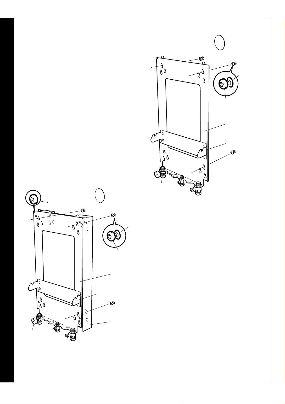
FITTING THE PIPING FRAME (Rear Flue outlet shown)
Note.
Fit the wall mounting frame either:
The flow isolating valve (A), c/w pressure gauge,
is supplied separately in the hardware pack. Fit
to the piping frame BEFORE mounting the
boiler.
a. Directly to the wall
!!
! Insert wall plugs.
!!
!!
! Put the screws into the wall plugs and leave
!!
10mm proud
!!
! Hang the frame onto the screws (take care to
!!
use the same hole position from each group as
previously chosen with the wall template) and
tighten up.
!!
! Locate the support bracket on the piping frame.
!!
or
Wall
plug
Four
positions
Screw
(10mm proud)
Piping frame
Support bracket
Ecl 2015
A
Four
positions
6mm Screw
positions
Screw
(10mm proud)
Piping
frame
Support bracket
Stand off
frame
Wall
plug
Four
A
Ecl 2086
b. Use the stand-off frame
(To allow pipework to be taken upwards).
!!
! Insert wall plugs.
!!
!!
! Put the screws into the wall plugs and leave
!!
10mm proud.
!!
! Hang the stand-off frame onto the screws and
!!
tighten up.
!!
! Fasten the piping frame to the stand-off
!!
frame with the 6mm screws and washers
provided.
!!
! Locate the support bracket on the piping
!!
frame.
If the clearances above and below the
Note.
boiler are less than the length of the pipes it
will be necessary to position the pipes behind
the wall mounting plate BEFORE the plate is
screwed to the wall.
Service connections may be made now, before mounting the
boiler, if required. Refer to Frames 24 & 25.
FLUE OUTLET
18
icos system -
Installation and Servicing

INSTALLATION
22
MOUNTING THE BOILER
IMPORTANT.
Before mounting the boiler on the wall fit the 'S' trap hose moulding/nut.
1. Ensure that the plastic plugs are removed from both the pipes before
mounting. N.B. Some spillage of water may occur from the pipework when
mounting the boiler to the frame.
2. Lift the boiler onto the wall mounting frame, locating it over the tabs at the
top of the frame.
3. Lower the boiler into position, engaging it onto the support bracket.
Note.
Ensure the condensate drain pipe is correctly positioned before
continuing.
4. Using the fibre washers supplied in the hardware pack, engage and then
tighten the 2 water unions.
5. Engage and tighten the gas union, ensuring that the rubber seal is in
place. DO NOT overtighten.
6. Connect a pipe to the safety drain outlet using the nut and olive supplied in
the boiler hardware pack.
7. Plug the user control (display unit, Pack A) into the control box. Refer to
Frame 35.
8. Screw the user control into position.
Ecl 2363
7
23
CONNECTING THE FLUE TO THE BOILER
Note.
1. Insert the flue assembly through the prepared hole in the
2. Locate the flue turret on the top of the boiler, ensuring
3. Locate the flue into the turret.
4. Secure the flue turret on top of
5. Flues over 1 metre
Before fitting the flue turret fill the condensate trap within the boiler by pouring a cupful of water into the flue outlet A.
Take care to ensure that the water is only poured into the flue outlet, and does not spill into the boiler casing.
wall.
that the turret gasket is in place. Check that the flue 'A'
seal located in the top of the flue manifold is secure and
giving an effective seal.
the boiler by inserting the
open ends of the
turret clamp under
the 2 studs and fixing
it in the middle with
the single M5 x
10mm pozi-hex
screw provided.
long.
Fix the flue support
bracket to the wall,
using the wall plugs
and wood screws.
NB. The support
bracket will utilise
one fixing hole only
whilst used in
conjunction with the
stand-off option.
4
5
2
A
4
1
Gasket
Ecl 6067
icos system -
Installation and Servicing
FLUE OUTLET
19

INSTALLATION
24
WATER CONNECTIONS
Notes.
For heating loads in excess of 60,000 Btu/h use 28mm x 22mm
1.
connectors to connect the boiler flow and return pipes to 28mm
system pipework.
2.
Do not subject any of the isolating valves to heat as the seals
may be damaged.
INSTALLATION
Isolating valve
(shown in the
open position)
Condensate drain
pipe located here
Pressure gauge
22mm copper pipe
FLOW
Drain
point
22mm copper pipe
Ecl 2365
Piping frame
Isolating valve
(shown in the
open position)
20
RETURN
icos system -
Installation and Servicing

INSTALLATION
25
GAS CONNECTION
IMPORTANT.The gas service cock contains a non-
metallic seal so must not be overheated when making
capillary connections.
Refer to Frame 2 for details of the position of the gas
connection.
The principle of the 1:1 gas valve ensures that the icos
system is able to deliver its full output at inlet pressures well
below those required by BS. 6891.
A boiler gas supply pipe length of 20m and not less than 15mm
O.D. can be connected to the boiler via the gas service cock
union.
Ensure that the gas supply pipe does not foul the boiler casing.
Refer to Frame 35 or 'Servicing' for details of the pressure test point
position.
26
SAFETY VALVE DRAIN
GAS IN
Rubber seal
(shown in the
open position)
Gas cock
Piping
frame
ecl 2539
INSTALLATION
The safety valve is located at the bottom RHS of the boiler.
The discharge pipe should be positioned so that the discharge of water or steam cannot create a hazard to the
occupants of the premises or damage the electrical components and wiring.
27
CONDENSATE DRAIN
Refer also to the British Gas document: 'Guidance Notes for
the Installation of Domestic Gas Condensing Boilers' (1989).
Front view
Side view
The condensate drain (provided in the h/ware
pack) must be connected from the boiler 'S'
trap to a drainage point, preferably within the
building.
Ensure that the condensate trap is full of water
before commissioning the boiler. Refer to
Frame 23.
The routing of the drain must be made to allow
a minimum fall of 1 in 20 away from the boiler,
throughout its length.
The drainage pipework must be arranged so
that obstruction (e.g. through freezing) of
external drainage pipe does not give rise to
spillage within the dwelling.
IMPORTANT.
If excessive external pipework cannot be
avoided, an additional siphon kit and insulation
are recommended, in order to prevent possible
freezing.
155mm
icos system -
Condensate
drain
Installation and Servicing
2025
All pipework and fittings in the condensate
drain system must be made of plastic. No
other materials may be used.
The drain outlet on the boiler is standard 21.5
mm overflow pipe. This size must not be
reduced in any part of its length.
21

INSTALLATION
28
FILLING
1. Remove the boiler front and sealing panels. Refer to
Frames 40 & 41.
2. Swing the control box down into the servicing position Refer to Frame 42.
3. Ensure that the isolating valves are open.
4. Fill and vent the system. Check for water soundness.
IMPORTANT - when filling:
a. The cap on the automatic air vent (refer to Frame
64) MUST be loose at all times.
INSTALLATION
When filling, there may be a slight water leak from
the vent therefore electrical connections should be
protected.
b. Bleed any air from the pump and ensure that it is
free to rotate.
i. Remove the vent plug
ii. Using a screwdriver, rotate the shaft several
times
iii. Replace the vent plug.
Some slight water leakage will occur.
Note.
Automatic air vent
Cap
Pump
Rotate the shaft to free
Vent plug
2072
22
icos system -
Installation and Servicing

29
ELECTRICAL CONNECTIONS
INSTALLATION
WARNING
A mains supply of 230 V ~ 50 Hz is required.
The fuse rating should be 3A.
All external controls and wiring must be suitable for mains
voltage.
Wiring external to the boiler MUST be in accordance with the
current I.E.E. (BS.7671) Wiring Regulations and any local
regulations.
30
A pictorial wiring diagram is shown in Frame 32.
1. Route the mains cable into the bottom rear centre of
the boiler.
2. Wire the permanent live supply into the 5-way remote
plug terminals, L3, N &
IMPORTANT. The permanent live is ESSENTIAL in
order for the advanced diagnostic controls to function
correctly.
3. Wire the switched live supply into terminal L2 or
connect L1 and L2 via external control switching, as
shown in Frame 31. In either case, remove the wire
link fitted to L1 and L2.
4. Secure the mains lead with the cable clamp.
5. Connect the mains lead connector. Ensure it is fully
located.
. This appliance MUST be earthed.
INTERNAL WIRING
.
Wiring should be 3 core PVC insulated cable, not less
than 0.75 mm2 (24 x 0.2mm), and to BS 6500 Table 16.
For IE reference should be made to the current ETCI
rules for electrical installations.
Connection must be made in a way that allows complete
isolation of the electrical supply such as a double pole
switch having a 3mm (1/8") contact separation in both
poles, or a plug and socket, serving only the boiler and
system controls. The means of isolation must be
accessible to the user after installation.
INSTALLATION
Note.
Ensure that the lengths of the current carrying conductors
are shorter than the earth conductor so that if the cable
slips in its anchorage the current carrying conductors
become taut before the earth conductor.
L3
L1
Remove link when connecting external programmer.
Mains Connector
(supplied in hardware pack)
Ecl 1542
Ecl2367
Socket
(fixed to boiler)
icos system -
Installation and Servicing
23

31
EXTERNAL ELECTRICAL CONTROLS
Wiring external to the boiler MUST be in accordance
with the current I.E.E. (BS.7671) Wiring Regulations and
any local regulations. For IE reference should be made
to the current ETCI rules for electrical installations.
The fuse rating should be 3A.
Room Thermostat
If the thermostat has a neutral connection, use it (it
provides for more energy efficient operation by reducing
switching temperature differentials).
INSTALLATION
Frost Protection
If parts of the pipework run outside the house or if the
boiler will be left off for more than a day or so then a
frost thermostat should be wired into the system. This is
usually done at the programmer, in which case the
programmer selector switches are set to OFF and all the
other controls MUST be left in the running position.
INSTALLATION
A
L3
Mains in
Optional
Frost 'stat
L1
Room 'stat
System
controls
N
if required
l 6069
Ec
The frost thermostat should be sited in a cold place but
where it can sense heat from the system.
If the boiler is installed in a garage it may be necessary
to fit a pipe thermostat, preferably on the return
pipework.
Designation of the terminals will vary but the
programmer and thermostat manufacturers' leaflets will
give full details.
IMPORTANT.
Ensure that the frost thermostat is wired so that the
system pump and / or external flow control valve is
energised as appropriate.
Diagram A shows an application to boilers fitted with a
room thermostat only.
Diagrams B & C show applications to boilers fitted with
alternative time controls.
B
C
Mains in
L3
L3
Optional
frost 'stat
L1
Room 'stat
if required
L1
Room 'stat
System
controls
l 6070
Ec
N
System
controls
Earths are not shown for clarity but must never be
omitted.
24
Mains in
Optional
frost 'stat
icos system -
l 6071
Ec
N
if required
Installation and Servicing
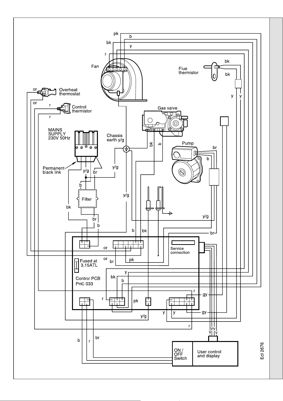
32
PICTORIAL WIRING DIAGRAM
INSTALLATION
LEGEND
b-blue
bk - black
br - brown
gy - grey
or - orange
pk - pink
r-red
v-violet
w-white
y-yellow
y/g- yellow/green
INSTALLATION
icos system -
Installation and Servicing
25

33
FUNCTIONAL FLOW WIRING DIAGRAM
INSTALLATION
DC
Fan
INSTALLATION
Mains switch
3
2
1
Flame detection electrode
r
Electrode
Return control
thermistor (not fitted)
Flow control thermistor
Ecl 2534
b
r
br
r
bk
y
pk
Flue thermistor
r
r
b
y/g
gy
r
gy
b
Filter
y/g
br
bk
External switch e.g.
PCB No.
PHC 033
y
y
v
v
v
v
room'stat, programmer
or
or
Overheat
thermostat
y/g
bk
b
p
y/g
br
b
br
y/g
DC Gas valve
Pump
N
L
E
LEGEND
b-blue
bk - black
br - brown
gy - grey
or - orange
pk - pink
34
COMMISSIONING AND TESTING
A. Electrical Installation
1. Checks to ensure electrical safety should be carried out by
a competent person.
2. ALWAYS carry out the preliminary electrical system
checks, i.e. earth continuity, polarity, resistance to earth
and short circuit, using a suitable test meter.
WARNING.
installation, open all windows and doors, extinguish naked lights and
r-red
v-violet
w-white
y-yellow
y/g- yellow/green
Whilst effecting the required gas soundness test and purging air from the gas
B. Gas Installation
1. The whole of the gas installation, including the meter,
should be inspected and tested for soundness and purged
in accordance with the recommendations of BS. 6891.
In IE refer to I.S.813:2002.
2. Purge air from the gas installation by the approved
methods only.
DO NOT SMOKE.
26
icos system -
Installation and Servicing

35
INITIAL LIGHTING
LEGEND
A. Boiler On/Off switch.
B. Thermostat knob.
C. Mains On neon.
D. Burner On Neon
E. Reset button.
F. Injector pressure test point.
G. Inlet pressure test point.
H. Gas service cock.
J. Casing pressure test point.
K. Overheat thermostat.
L. Flue thermistor.
M. Flow thermistor.
N. Automatic air vent.
P. Control panel (Servicing position).
R. Pressure gauge.
S. Flow isolating valve.
T. Return isolating valve.
INSTALLATION
INSTALLATION
1. Check that the system has been filled and that the boiler is
not airlocked. Ensure the automatic air vent cap (N) is
open.
Note.
It is important the burner is not operated before the system is
fully vented of air. If it is necessary to operate the appliance
pump to assist venting of the air this must be done with the
gas service cock turned off.
2. Refit the boiler sealing panel. Refer to Frame 41.
3. Check that all the drain cocks are closed and that the
isolating valves (T and S) are OPEN.
4. Check that the electrical supply is OFF.
5. Check that the boiler on/off switch (A) is off.
6. Check that the gas service cock (H) is OPEN.
7. Carefully align the user control and push gently into place.
Secure with the single screw located underneath.
8. Slacken the screw in the inlet pressure test point (G) and
connect a gas pressure gauge via a flexible tube.
9. Swing the control panel to the working position and secure
with the clamp.
10.Reconnect the ignition lead to the control box.
11. Connect the low voltage electrical lead from the user
control to the control box (refer to Frame 42) and screw
the control into position.
12.Switch the electricity supply ON and check all external
controls are calling for heat.
The display
The user control has one neon and one display to inform the
user about the status. The display will show the status of the
boiler. The neon will show the status of the flame. If no flame
is detected the neon is blinking. When the flame is detected
the neon will be lit permanently.
Below is a list with the display function in normal operation.
Standby, no demand for heat present.
Boiler is active for central heating.
Boiler is in lockout for a specific error. Display will be
blinking, alternating with a number or letter to show which
error is detected.
Boiler in lockout for a specific error. Display will be
blinking, alternating with a number or letter to show which
is detected.
icos system -
Installation and Servicing
27
INSTALLATION
36
INITIAL LIGHTING - continued
13.Set the boiler thermostat knob (B) to position 6 and
switch the boiler on/off switch (A) to ON. The RED
mains on neon (C) should now be illuminated. The boiler
control should now go through its ignition sequence until
the burner is established.
14.If the boiler does not light after 3 attempts, fault code
will be displayed. Press the reset button (E) and the
boiler will repeat its ignition sequence.
When the burner is established the GREEN 'Burner On'
neon (D) will be illuminated and the LED display will
show status .
15.Ensure that with the boiler operating the dynamic gas
INSTALLATION
pressure is able to obtain maximum output. Refer to
Table 2.
N.B. The principle of the 1:1 gas valve ensures that the icos
system is able to deliver its full output at inlet pressures
well below those required by BS.6891.
37
GENERAL CHECKS
Make the following checks for correct operation:
1. Ensure that the external controls are calling for heat.
After ignition the display should read:
green neon on.
IMPORTANT.
The gas input to the burner is regulated by the gas
valve according to the air flow produced by the fan. It
is NOT user-adjustable. Any interference to sealed
settings on the gas valve will adversely affect
operation and render our warranty void.
16.Set the boiler on/off switch (A) to OFF.
17.Swing the control box into the servicing position. Refer to
Frame 42.
18.Remove the pressure gauge and tube. Tighten the sealing
screw in the pressure test point. Ensure a gas tight seal is
made.
19.Swing the control box back into its working position and
secure. Reconnect the ignition lead.
20.Refit the user control.
21.Refit the boiler front and bottom panels.
22.Switch the boiler on again.
7. With the system still hot, turn off the gas, water and
electricity supplies to the boiler and drain down to
complete the flushing process.
Note.
A flushing solution should be used during the
flushing procedure: Flushing solutions Fernox
Superfloc, Sentinel X300 (new systems) or X400
(existing systems). Refer to Frame 6.
2. Gas Rate
Check the boiler gas rate when the boiler is at full
output checked at the gas meter, with no other
appliance in use.
Refer to Table 2 for gas rates.
3. Set the external controls to OFF. The burner should
go off and the pump continue to run for a few
seconds.
The display should read:
returning to
when the pump stops.
4. Check the correct operation of the programmer (if
fitted) and all other system controls. Operate each
control separately and check that the main burner
responds.
Water circulation system
5. With the system COLD, check that the initial
pressure is correct to the system design
requirements. For pre-pressurised systems, this
should be 1.0 bar.
6. With the system HOT, examine all water connections
for soundness. The system pressure will increase
with temperature rise but should not exceed 2.5 bar.
8. Refill and vent the system, add inhibitor (see Frame 6),
clear all air locks and again check for water soundness.
Affix the water treatment warning label, supplied in the
hardware pack, in a
to prevent the use of incorrect water treatment
additives.
9. Reset the system initial pressure to the design
requirement.
10.Balance the system. Refer to Frame 5.
11. Check the condensate drain for leaks and check that it
is discharging correctly.
12.Finally, set the controls to the User's requirements.
Note.
The pump will operate briefly as a self-check once
every 24 hours in the absence of any system demand.
prominent position
on the system,
WATER TEMPERATURE
Water temperature can be selected via the
thermostat (B)
Knob Setting Flow
Temp
o
C (oF)
Max 82 (180)
Min 30 (86)
28
icos system -
Installation and Servicing

INSTALLATION
38
HANDING OVER
After completing the installation and commissioning of the system the
installer should hand over to the householder by the following actions:
1. Hand the User Instructions to the householder and
explain his/her responsibilities under the relevant
national regulations.
2. Explain and demonstrate the lighting and shutting
down procedures.
3. The operation of the boiler and the use and adjustment
of all system controls should be fully explained to the
householder, to ensure the greatest possible fuel
economy consistent with the household requirements of
heating.
Advise the User of the precautions necessary to prevent
damage to the system and to the building in the event
of the system remaining inoperative during frosty
conditions.
4. Explain the function and the use of the boiler heating
controls.
5. Explain the function of the boiler fault mode.
Emphasise that if a fault is indicated, the boiler should
be turned off and a CORGI registered installer
consulted. In IE contact a Competent Person.
6. Explain and demonstrate the function of time and
temperature controls, radiator valves etc., for the
economic use of the system.
7. If any programmer is fitted then draw attention to the
Programmer Users Instructions and hand them to the
householder.
8. Loss of system water pressure
Explain that the dial underneath the boiler indicates the
central heating system pressure and that if the normal
COLD pressure of the system is seen to decrease over a
period of time then a water leak is indicated. In this event a
CORGI registered installer should be consulted. In IE
consult a Competent Person.
WARNING.
Do not fire the boiler if the pressure has reduced to zero
from the original setting.
9. After installation, commissioning and customer handover please complete the
book and leave this with the customer. For IE, it is
necessary to complete a “Declaration of Conformity” to
indicate compliance to I.S.813:2002.
10.Stress the importance of regular servicing by a CORGI
registered installer and that a comprehensive service
should be carried out AT LEAST ONCE A YEAR. In IE
servicing work must be carried out by a Competent
Person.
11. As the installer you may wish to undertake the service
contract yourself or alternatively offer to the customer the
benefits of the Ideal Care Scheme, details of which are
outlined in the householder pack supplied with this boiler.
appliance log
INSTALLATION
icos system -
Installation and Servicing
29

39
SERVICING SCHEDULE
SERVICING
To ensure the continued safe and efficient operation of the
appliance it is recommended that it is checked at regular
intervals and serviced as necessary. The frequency of
servicing will depend upon the installation condition and usage
but should be carried out at least annually.
It is the law that any service work must be carried out by a
CORGI registered installer. In IE service work must be
carried out by a competent person.
Note.
1. Light the boiler and carry out a pre-service check, noting
2. Check the gas consumption.
3. Connect a suitable gas analyser to the sampling point on
4. Clean the main burner.
5. Clean the heat exchanger.
6. Check the condition of the combustion chamber
SERVICING
Some aluminium oxide build-up on the heat
exchanger fins is usual with this type of condensing
boiler. Though removal is recommended annually,
the heat exchanger MUST be inspected and cleaned
after a MAXIMUM of 2 years operation
any operational faults.
the top of the boiler (refer to Frame 41) or into the flue
terminal if access is possible (optional test).
For correct boiler operation the CO/CO
gas should not be greater than 0.004 ratio. If this is the
case, and the gas input is at least 90% of the nominal,
then no further action need be taken. If not, proceed to
Step 4 but see note above.
insulation. Any cracked/damaged pieces should be
replaced.
.
content of the flue
2
7. Check the main injector for blockage or damage.
8. Wherever possible remove and clean the condensate 'S'
trap (refer to Frame 45) and check the drain for blockage.
9. Check that the flue terminal is unobstructed and that the
flue system is sealed correctly.
The servicing procedures are covered more fully in Frames
40 to 47 and MUST be carried out in sequence.
Note.
WARNING.
service cock, and switch OFF and disconnect the
electricity supply to the appliance before servicing.
IMPORTANT.
10.After completing the servicing or exchange of components
11. When work is complete the sealing panel MUST be
In order to carry out either servicing or replacement of
components the boiler front panel and sealing panel
must be removed. Refer to Frames 40 and 41.
Always turn OFF the gas supply at the gas
always test for gas soundness and carry out functional
checks as in 2 and 3 above.
correctly refitted, ensuring that a good seal is made.
Do NOT OPERATE the boiler if the sealing
panel is not fitted
12.If, for any reason, the condensate trap 'S' has been
removed ensure that the trap is refilled with water before
reassembly.
13.Complete the service section in the Benchmark log book.
40
BOILER FRONT PANEL REMOVAL
1. Remove the 2 retaining screws from the
underside of the boiler.
2. Pull the panel forward at the bottom and
lift to disengage it from the top lugs.
Ecl 1547
30
icos system -
Installation and Servicing

SERVICING
41 BOILER SEALING PANEL / BOTTOM PANEL REMOVAL
1. To remove the sealing panel remove the 4
screws.
2. Remove the panel.
3. To remove the bottom panel remove the 2
screws.
4. Pull the right hand side of the panel down.
Slide it to the right and withdraw.
42
THE CONTROL BOX IN THE SERVICING POSITION
1
Flue gas
sampling
point
Ecl 2333
1. Remove the 2 screws and withdraw the user
control.
2. Unplug the low voltage electrical lead from the
back of the user control.
3. Unplug the ignition lead from the bottom of the
control box.
4. Turn the clamp, swing the control box down and
pull slightly forward.
4
Clamp
Control box
1
SERVICING
User control
Swing control panel down and forward into service position
icos system -
Installation and Servicing
Ecl 2369
Ecl 2370
3
2
31

SERVICING
43
FAN AND VENTURI ASSEMBLY REMOVAL AND CLEANING
1. Disconnect the electrical leads from the fan.
2. Undo the gas pipe union connection to the injector
housing.
3. Undo the screw on the fan mounting bracket.
4. Lift off fan and venturi assembly.
5. Inspect the injector for blockage or damage.
1
4
3
SERVICING
Ecl 6073
44
BURNER REMOVAL AND CLEANING
1. Remove the 6 screws retaining the burner
(the 3 screws at the rear are extended to
ease access).
2. Lift off the burner from the combustion
chamber.
IMPORTANT
The burner head is a ceramic plaque
construction. Care must be taken to
ensure that the burner is not placed
down upon its face as this may cause
damage to the ceramic.
3. Brush off any deposits that may be on the
ceramic with a SOFT brush.
4. Inspect the sealing gasket around the
burner and combustion chamber
insulation for any signs of damage.
Replace as necessary.
Note.
Take care not to disturb the detection earth
probe at the rear of the combustion chamber.
2
1
2
Detection
earth
probe
4
Ecl 6074
32
icos system -
Installation and Servicing
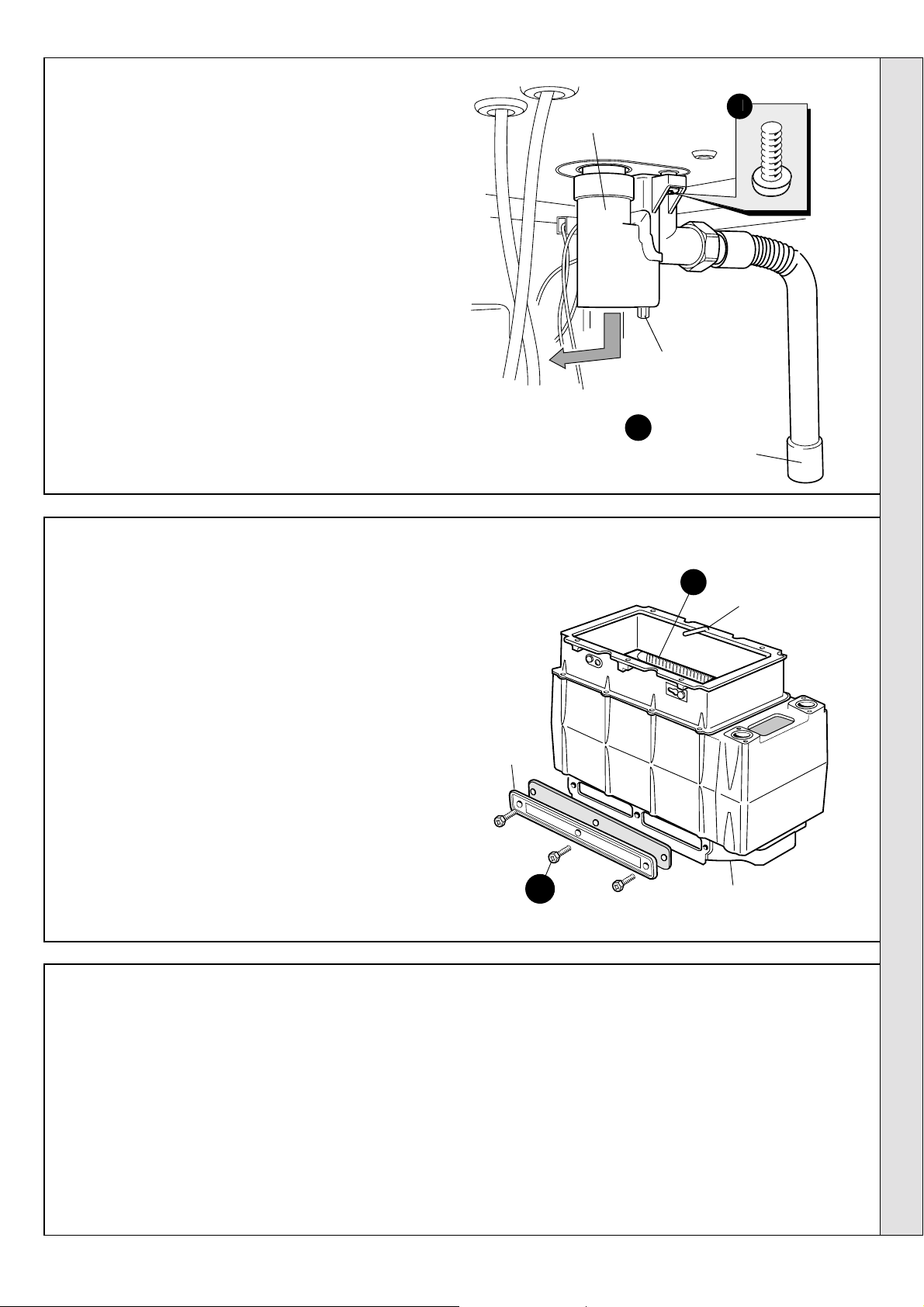
45
CLEANING THE CONDENSATE 'S' TRAP
SERVICING
1. Swing the control box down into the servicing
position. Refer to Frame 42.
2. Disconnect the condensate drain pipe.
3. Remove the screw and elongated bolt, pull
the trap down and forward to remove.
4. Flush out any deposits with clean water.
46
CLEANING THE HEAT EXCHANGER
Condensate trap
Ecl 2429
Elongated bolt
2
Condensate drain pipe
1. Remove ignition and flame detection electrodes. Refer to
Frames 54 & 55.
2. Remove the 3 screws retaining the sump cover and remove.
3. Using a suitable tool as supplied in the standard British
Gas Flue brush kit, clean between the heat exchanger fins
from the top of the heat exchanger.
4. Access to the base of the heat exchanger is now possible.
Brush clean any deposits from the base of the heat
exchanger and remove any loose deposits from the sump.
5. Inspect the ignition and detection electrodes. Ensure that
they are clean and in good condition - replace if necessary.
6. Check that the ignition and detection gaps are correct.
Refer to Frames 54 & 55.
7. Check the condition of the combustion chamber insulation.
Any cracked/damaged pieces should be replaced.
Note.
Take care not to disturb the detection earth probe at the rear
of the combustion chamber.
47
REASSEMBLY
Reassemble the boiler in the following order:
1. Refit the condensate 'S' trap, ensuring that it is full of water.
2. Refit the sump cover.
3. Refit the electrodes. (Check dimensions; Frames 54 &
55).
4. Refit the burner.
5. Refit the fan / venturi assembly.
6. Reconnect the fan electrical leads.
7. Refit the boiler sealing panel.
3
Detection earth
probe
Sump cover
2
IMPORTANT.
Ensure that the boiler sealing panel is correctly
fitted and that a good seal is made.
8. Swing the control box back into its working position
and secure.
9. Refit the display unit.
10.Refit the boiler front and bottom panels.
11. Turn on the gas supply at the gas service cock.
12.Reconnect the electrical supply.
Heat exchanger
SERVICING
Ecl 2372
icos system -
Installation and Servicing
33

48
REPLACEMENT OF COMPONENTS
GENERAL
SERVICING
When replacing ANY component :
1. Isolate the electricity supply.
2. Turn off the gas supply.
3. Remove the boiler front panel. Refer to Frame 40.
After replacing ANY component check operation of the
boiler including gas soundness, gas rate and combustion
test.
THE BOILER MUST NOT BE OPERATED WITHOUT THE SEALING PANEL FITTED
49
FLUE THERMISTOR REPLACEMENT
1. Refer to Frame 48.
2. Remove the boiler front and sealing panels. Refer to
Frames 40 & 41.
3. Unplug the electrical lead.
4. Disconnect the flue sampling tube from the thermistor
housing.
5. Remove the aluminium nipple securing the thermistor to
the flue manifold.
6. Withdraw the thermistor.
SERVICING
7. Fit the new flue thermistor, using the gasket supplied.
8. Reassemble in reverse order.
9. Check the operation of the boiler. Refer to Frame 48.
IMPORTANT.
When work is complete, the sealing panel, if removed, must
be correctly refitted - ensuring that a good seal is made.
Notes.
1. In order to assist fault finding, the control panel has an
LED diagnostic display. The key to boiler fault conditions is
shown in Frame 70 .
2. In order to replace components in Frames 62-68 it is
necessary to drain the boiler. Refer to Frame 65.
Thermistor
Flue
sampling
tube
nipple
50
FAN REPLACEMENT
1. Refer to Frame 48.
2. Remove the boiler front and sealing panels. Refer to
Frames 40 & 41.
3. Disconnect the electrical leads from the fan.
4. Undo the gas pipe union connection to the injector
housing.
5. Remove the screw retaining the fan mounting
bracket.
6. Remove the fan and venturi assembly.
7. Unscrew the 3 screws and remove the venturi
assembly,
relation to the fan body.
8. Transfer the venturi assembly to the new fan, replacing the
gasket if evidence of damage or deterioration is visible.
9. Fit the new fan / venturi assembly.
10.Reassemble the boiler in reverse order, taking care not to
overtighten the screw on the fan mounting bracket.
11. Check the operation of the boiler. Refer to Frame 48.
noting the orientation of the venturi in
Ecl 2097
Orifice plate
Gasket
7
3
5
Ecl 2373
4
34
icos system -
Installation and Servicing

SERVICING
51
BURNER INJECTOR REPLACEMENT
1. Refer to Frame 48.
2. Remove the boiler front and sealing panels. Refer to Frames
40 & 41.
3. Disconnect the electrical leads from the fan.
4. Undo the gas pipe union connection to the injector housing.
5. Remove the screw retaining the fan mounting bracket.
6. Remove the fan and venturi assembly. Refer to Frame 43.
7. Remove the 2 injector housing screws.
8. Withdraw the injector housing.
9. Fit the new injector housing, complete with injector.
10.Reassemble in reverse order, ensuring that the new gas seal
supplied is located correctly in the injector housing.
11. Check operation of the boiler. Refer to Frame 48.
52
BURNER REPLACEMENT
1. Refer to Frame 48.
2. Remove the boiler front and sealing panels. Refer to
Frames 40 & 41.
3. Remove the fan assembly. Refer to Frame 43.
4. Remove the 6 screws securing the burner (the 3 screws at
the rear are extended to ease access).
5. Lift off the burner from the combustion chamber.
6. Fit the new burner, replacing any damaged or deteriorating
sealing gasket.
7. Reassemble in reverse order.
8. Check the operation of the boiler. Refer to Frame 48.
Note.
Take care not to disturb the detection earth probe at the rear
of the combustion chamber.
Ecl 2559
7
Injector
Fan
Gas pipe union
5
Mounting bracket
4
Ecl 2400
5
Detection
earth
probe
SERVICING
6
53
CONTROL THERMISTOR AND OVERHEAT THERMOSTAT REPLACEMENT
1. Refer to Frame 48.
2. Remove the boiler front and sealing panels. Refer to Frames
40 & 41.
3. Unclip the thermistor / thermostat from the flow pipe and
withdraw it from the controls compartment.
icos system -
Flow pipe
Ecl 6084
Control thermistor
Installation and Servicing
Overheat thermostat
4. Disconnect the electrical leads from the thermistor/
thermostat.
5. Reconnect the electrical leads and reassemble in
reverse order, ensuring the spring clip is securely on
the pipe.
6. Check the operation of the boiler. Refer to Frame 48.
35

54
IGNITION ELECTRODE REPLACEMENT
SERVICING
1. Refer to Frame 48.
2. Remove the boiler front and sealing panels. Refer to
Frames 40 & 41.
3. Swing the control box down into the servicing position -
Refer to Frame 42.
Ecl 6076
4. Unplug the ignition electrode lead from the control box.
5. Remove the screw holding the ignition electrode to the
combustion chamber.
6. Remove the electrode, taking care not to dislodge the
grommet from the casing.
7. Remove earth lead from the ignition electrode.
8. Fit the new ignition electrode, using the new gasket
supplied. Check dimensions as shown.
9. Reassemble in reverse order.
10.Check the operation of the boiler. Refer to Frame 48.
11mm
Spark gap 3mm
+2
-0
+0
-4
Straight edge
5
SERVICING
55
FLAME DETECTION ELECTRODE REPLACEMENT
1. Refer to Frame 48.
2. Remove the boiler front and sealing panels. Refer to
Frames 40 & 41.
3. Swing the control box down into the servicing position.
Refer to Frame 42.
Ecl 2375
Ecl 6077
4. Unplug the flame detection electrode lead from the
control box.
5. Remove the screw holding the flame detection electrode
to the combustion chamber.
6. Unbolt the flame detection electrode earth lead from the
earth point beneath the boiler.
7. Remove the electrode, complete with grommet.
8. Fit the new flame detection electrode, using the new
gasket supplied. Check dimensions as shown.
9. Reassemble in reverse order.
10.Check the operation of the boiler. Refer to Frame 48.
25mm
+ 2
- 2
Straight edge
36
5
Ecl 6078
icos system -
Installation and Servicing

SERVICING
56
COMBUSTION CHAMBER INSULATION REPLACEMENT
The insulation boards used in the combustion chamber of this
product are made of high temperature glass fibres with a
binder of organic and inorganic materials.
Caradon Ideal Limited recommend that, for your own comfort
and safety and to comply with good working practice, the
procedure described below is followed:
1. Refer to Frame 48.
2. Remove the boiler front and sealing panels. Refer to
Frame 40 & 41.
3. Remove the fan / venturi assembly. Refer to Frame 43.
4. Remove the burner. Refer to Frame 44.
5. Remove the screw holding the ignition electrode and
withdraw it from the combustion chamber
6. Remove the screw holding the flame detection electrode
and withdraw it from the combustion chamber.
Prior to removal of the board the following protective
equipment should be worn:
• Face mask supplied with the spare part
• Gloves supplied with the spare part
7. Remove the detection earth probe.
8. Damp down the combustion chamber area containing the
insulation boards.
9. Remove the split pin and washer from the RHS of the
combustion chamber.
10.Remove the insulation boards. The replacement boards
are supplied in a plastic bag. This bag should be retained
and the discarded boards should now be placed into it.
11. Sweep any dampened particles and place in the plastic
bag.
12.Fit new insulation boards.
The boards are designed to be interlocking and should
Note.
be fitted as shown.
13.Fit the new split pin and washer in the RHS of the
chamber.
14.Remove the gloves and face mask and place them in the
plastic bag.
15.Wash your hands and any areas of skin which may have
come into contact with any of the particles from the
insulation board.
Seal the plastic bag and dispose of it and its contents
Note.
into a commercial tip.
16.Reassemble in reverse order.
17.Check operation of the boiler. Refer to Frame 48.
Fit insulation in the following order:
1. Front.
2. Left Hand Side.
3. Rear.
4. Right Hand Side.
6
Front
LH Side
SERVICING
Rear
RH Side
icos system -
Installation and Servicing
5
Ecl 2377
37

SERVICING
57
GAS CONTROL VALVE REPLACEMENT
1. Refer to Frame 48.
2. Remove the boiler front and bottom panels. Refer to Frames 40 &
41.
8
Mounting bracket
11
3. Swing the control box down into the
servicing position. Refer to Frame 42.
4. Unplug the electrical lead from the gas
control valve and disconnect the earth wire.
5. Remove the sensing tube from the gas
control valve.
6. Undo the gas inlet pipe union at the gas
service cock.
7. Undo the union nut on the outlet of the gas
control valve.
8. Slacken the screw securing the valve
mounting bracket and withdraw the valve,
complete with bracket and inlet pipe.
9. Transfer the mounting bracket and gas inlet
pipe to the new gas control valve.
4
SERVICING
6
58
CONDENSATE 'S' TRAP REPLACEMENT
1. Refer to Frame 48.
2. Remove the boiler front and bottom panels.
Refer to Frames 40 & 41.
3. Swing the control box down into the
servicing position. Refer to Frame 42.
7
10.Fit the new gas control valve, ensuring that
any seals showing damage or deterioration
are replaced. Reassemble in reverse order.
11. Ensure the sensing tube is correctly
replaced and not kinked or blocked in any
way.
12.Check operation of the boiler. Refer to
Frame 48.
ECL 6079
Condensate
'S' trap
5
4. Disconnect the condensate drain pipe.
5. Remove the screw and elongated bolt, pull
the trap down and forward to remove.
6. Transfer the drain pipe to the new trap and
reassemble in reverse order.
7. When reassembling ensure the trap is full
of water.
8. Check operation of the boiler. Refer to
Frame 48.
38
Elongated bolt
4
Condensate drain
icos system -
Ecl 6080
Installation and Servicing

SERVICING
59
CONTROL BOX REPLACEMENT
1. Refer to Frame 48.
2. Remove the boiler front and bottom panels. Refer to
Frames 40 & 41.
3. Swing the control panel down into the servicing position.
Refer to Frame 42.
4. Unplug the user control electrical lead and low voltage
lead from the control box and remove the control. Refer
to diagram A.
5. Return the control box to the working position and
secure with the clamp. Unscrew the mounting bracket
screws to remove the bracket. Refer to diagram B.
6. Release the clamp and carefully remove the control box
from the hinge arms. Refer to diagram C.
7. Unplug all the electrical wiring from the control box and
remove.
8. Transfer mounting bracket and hinge screws to the new
control box.
C.
9. Reassemble in reverse order, ensuring that the control box
is located correctly in the housing before reconnecting the
electrical wiring.
10.Check operation of the boiler. Refer to Frame 48.
A.
Ecl 2082
Electrical lead
Control box
B.
Control box
Clamp
Low voltage lead
Screws
Control
box
Hinge arms
60
MAINS SWITCH REPLACEMENT
1. Refer to Frame 48.
2. Remove boiler front and bottom panels. Refer to
Frames 40 & 41.
3. Remove the 2 screws and allow the user control to
lower.
4. Push out the mains switch from the rear, as shown.
Control box mounting bracket
5. Fit the new switch, ensuring that the electrical leads are
replaced on the correct terminals (refer to Frame 33) and the
key on the switch is correctly aligned with the slot in the plastic
moulding.
6. Reassemble in reverse order.
7. Check operation of the boiler. Refer to Frame 48.
SERVICING
Ecl 2380
User control
icos system -
3
Installation and Servicing
Display
unit
Ecl 2431
Display unit
Slot
Key
Mains switch
Electrical lead
39

61
USER CONTROL REPLACEMENT
Note.
Only the display unit is replaced.
1. Refer to Frame 48.
2. Loosen the screw on the underside of
the user control.
3. Pull the display unit forward to remove.
4. Push the new display unit into position.
5. Reassemble in reverse order.
6. Check operation of the boiler. Refer to
Frame 48.
SERVICING
Screws
2
Ecl 2382
Display
unit
SERVICING
Ecl 2381
User control
62
PRESSURE GAUGE REPLACEMENT
1. Refer to Frame 48.
2. Drain the boiler. Refer to Frame 65.
3. Unscrew the pressure gauge and discard.
4. Fit the new pressure gauge, using a suitable jointing
compound.
5. Refill the boiler. Refer to Frame 28.
6. Check operation of the boiler. Refer to Frame 48.
Pressure gauge
40
Flow isolation valve
(shown in the open position)
icos system -
Installation and Servicing
2041

63
SAFETY RELIEF VALVE REPLACEMENT
SERVICING
1. Refer to Frame 48.
2. Remove the boiler front and bottom panels. Refer to
Frame 40 & 41.
3. Drain the boiler. Refer to Frame 65.
4. Remove the discharge the pipe.
5. Unscrew the 4 screws securing the rear support plate
and withdraw the plate.
Note.
The M4 screws fit the casing and the self-tapping
screws fit the plastic pump and valve housing as
shown .
M4 screw
Self tapper
screws
Ecl 2432
M4 screw
Support plate
6. Withdraw the securing pin.
7. Remove the safety valve.
8. Fit the new safety valve and refit the securing pin.
9. Reassemble in reverse order, ensuring correct location of
screws in support plate and that tabs on the pump and
valve housings engage in slots.
10.Reconnect the discharge pipe.
11. Refill the boiler. Refer to Frame 28.
12.Check operation of the boiler. Refer to Frame 48.
Ecl 2091
Securing pin
Safety relief valve
Discharge pipe
64
AUTOMATIC AIR VENT REPLACEMENT
1. Refer to Frame 48.
2. Remove the boiler front and sealing panels. Refer to
Frames 40 & 41.
4. Drain the boiler. Refer to Frame 65.
5. Unscrew the air vent from the extension pipe on the
boiler boss.
6. Fit the new air vent, complete with 'O' ring provided, and
reassemble in reverse order.
Note.
IMPORTANT. Ensure that the vent cap is loose (A).
6. Refill the boiler. Refer to Frame 28.
In the event that the extension pipe is removed at
the same time as the air vent, remove it from the air
vent and refit it into the heat exchanger, ensuring
that its 'O' ring seal is in place before fitting the new
air vent.
SERVICING
Vent cap (A)
Air vent
7. Check operation of the boiler. Refer to Frame 48.
icos system -
Installation and Servicing
Ecl 2098
41

65
DRAINING THE BOILER
1. Refer to Frame 48.
2. Remove the boiler front and bottom panels. Refer to
Frame 40 & 41.
3. Close all the water isolating valves on the piping
frame.
4. Attach a length of hose to the drain point and open
the drain valve.
5. After replacing any component on the boiler,
close the drain valve, remove the hose and open
all system isolating valves before proceeding to
check operation of the boiler.
6. Check operation of the boiler. Refer to Frame 48.
SERVICING
Drain valve
Drain point
Isolating valves
TO OPEN
isolating valve
(shown closed)
SERVICING
66
PUMP HEAD REPLACEMENT
1. Refer to Frame 48.
2. Remove the boiler front and bottom panels. Refer
to Frame 40 & 41.
3. Drain the boiler. Refer to Frame 65.
4. Swing the control box down into the servicing
position. Refer to Frame 42.
5. Disconnect the electrical lead from the pump.
6. Remove the 4 Allen screws retaining the pump
head.
7. Remove the pump head.
8. Fit the new pump head.
9. Reassemble in reverse order.
10.Refill the boiler. Refer to Frame 28.
11. Check operation of the boiler. Refer to Frame 48.
2104
Electrical
6
lead
Ecl 2047
42
Pump head
icos system -
Installation and Servicing

SERVICING
67
HEAT EXCHANGER REPLACEMENT
Refer also to Frames 7 & 8 - 'Boiler exploded view'.
IMPORTANT
Before starting the removal procedure, protect the gas and
electrical controls with a waterproof sheet or plastic bag.
1. Refer to Frames 48.
2. Remove the boiler front, sealing and bottom panels.
Refer to Frames 40 & 41
3. Drain the boiler. Refer to Frame 65.
4. Remove the control box and place on one side. Refer to
Frame 59.
5. Remove the fan / venturi assembly and place on one
side. Refer to Frame 43.
6. Remove the burner and place on one side. Refer to
Frame 44.
7. Remove the ignition and detection electrodes. Refer to
Frames 54 & 55.
8. Release the flue from the turret. Refer to Frame 23.
9. Remove the turret from the boiler. Refer to Frame 23.
10.Remove the automatic air vent complete with adapter.
Refer to Frame 64.
11. Release the M5 nut retaining the flue casting spring clip
and remove the spring clip.
12.Remove the M5 x 10 screw retaining the flue casting.
13.Release the silicon tubing from the sampling point.
14.Release the electrical connection to the flue thermistor.
15.Remove the 2 M5 x 10 flue spring clip retaining bracket
screws and remove the bracket.
16.Remove the flue casting.
17.Remove the edge clip securing the flue thermistor wiring.
18.Remove the blind grommet to gain access to the return
pipe securing bracket.
19.Remove the M5 screw and remove the return pipe securing
bracket by sliding forwards.
20.Remove the overheat thermostat and the control
thermistor. Refer to Frame 53.
21.Remove the securing pin to release the flow pipe.
22.Remove the condensate 'S' trap. Refer to Frame 45.
23.Remove the 2 M5 screws securing the interpanel to the
back panel.
24.Slide the heat exchanger and interpanel assembly upward
to disengage and remove from the casing, complete with
the return pipe.
25.Remove the 2 M6 countersunk screws, remove the
interpanel and transfer to the new heat exchanger.
26.Remove the M5 screw and remove the flow pipe securing
bracket.
27.Remove the flow pipe and transfer to the new heat
exchanger.
28.Reassemble in reverse order, replacing gaskets or seals if
any sign of damage or deterioration is evident.
Note.
The heat exchanger is supplied with new combustion chamber
insulation boards. These should be fitted (refer to Frame 56)
before the burner and fan / venturi assembly and before the
ignition and flame detection electrodes are replaced.
29.Refill the boiler. Refer to Frame 28.
30.Check operation of the boiler. Refer to Frame 48.
SERVICING
Overheat
thermostat
Flow pipe
Control
thermistor
21
12
13
14
Edge clip
11
17
18
10
15
Return pipe
securing bracket
19
Interpanel
26
Spring clip
25
23
Flow pipe
securing bracket
27
Ecl 2536
icos system -
Installation and Servicing
43

SERVICING
68
EXPANSION VESSEL REPLACEMENT
1. Refer to Frame 48 .
2. Drain the boiler. Refer to Frame 65.
3. Unscrew all the gas and water connection unions on the
boiler side of the valves.
4. Remove the screw from the turret clamp and remove the
turret.
5. Lift the complete boiler from the wall mounting frame and
place on a flat surface, face down, to expose the expansion
vessel.
6. Unscrew the union nut on the vessel water connection
pipe.
7. Unscrew the 2 screws from the securing clamp and
remove.
8. Remove the expansion vessel.
9. Fit the new expansion vessel.
10.Reassemble in reverse order.
11. Refill the boiler. Refer to Frame 28
12.Check operation of the boiler. Refer to Frame 48.
If preferred and for convenience, a new expansion
Note.
vessel may be installed else where in the heating system,
providing it ensures equivalent system protection.
Expansion vessel
Securing clamp
6
7
SERVICING
69
BOILER SEALING PANEL SEAL REPLACEMENT
1. Refer to Frames 48.
2. Remove the boiler front and sealing panels.
Refer to Frames 40 & 41.
3. Remove the old seal from the casing and
thoroughly clean the casing surfaces.
4. Fit the new adhesive seals, noting that they
are supplied to the correct length for the
relevant sides.
5. Reassemble in reverse order.
Note.
6. Check operation of the boiler. Refer to
Ensure that the boiler sealing panel is
correctly seated, compressing the seal
to make an airtight joint.
Frame 48.
Ecl 2537
Rear view of the boiler
Seals
3
44
icos system -
Ecl 2435
Installation and Servicing
FAULT FINDING
70
FAULT FINDING CHART MAIN MENU
In order to assist fault finding the boiler has an LED diagnostic display. The key to the display codes is as follows:
ALTERNATING 'L' 'F'
ALTERNATING 'L' 'E'
ALTERNATING 'L' 'A'
ALTERNATING 'L' '8'
ALTERNATING 'H' '1'
ALTERNATING 'H' '4'
GO TO FRAME 71
GO TO FRAME 72
GO TO FRAME 73
GO TO FRAME 74
GO TO FRAME 75
GO TO FRAME 76
icos system -
ALTERNATING 'H' 'F'
ALTERNATING 'H' 'n'
ALTERNATING 'H' 'E'
Installation and Servicing
GO TO FRAME 77
GO TO FRAME 78
GO TO FRAME 72
FAULT FINDING FAULT FINDING FAULT FINDING FAULT FINDING
45
71
L.....F.... (FLAME DETECTION ERROR)
FAULT FINDING
If the boiler reset button is
pressed does the boiler ignite for
a short time then extinguish?
YES
Check the detection electrode and
associated harness for:
continuity, visual condition, position
(
Refer to Frame 54
Replace as necessary.
).
Replace ignition electrode and associated
harness as necessary
NO
Check the ignition electrode and associated harness
for: continuity, visual condition, position
Is gas pressure available at
the boiler inlet ?
YES
Is 200 V DC supply
available at the gas valve ?
(see note).
YES
(Refer to Frame 53).
Are these functioning correctly ?
NO
Replace gas valve
NO
NO
YES
Check gas supply
and rectify fault
Check gas valve
wiring for
continuity
Replace PCB
Note.
Due to the wave form of the rectified voltage, the reading will vary depending on the type of meter used to
measure the value (some may measure the possible peak voltage of 339V). In general terms a reading
greater than 150V indicate that the correct voltage is supplied to the gas valve.
72
L.....E.... or H.....E.... (BOARD ERROR)
Internal fault within the PCB
Replace PCB
FAULT FINDING FAULT FINDING FAULT FINDING FAULT FINDING
46
icos system -
Installation and Servicing
73
L......A..... (OVERHEAT ERROR)
FAULT FINDING
Can the overheat condition be reset by pressing
the boiler reset button when the system is cold ?
Is the boiler and CH system filled with
water and all isolation valves open ?
Does the pump setting give a differential
across the boiler in excess of 25 oC ?
Set CH control knob to maximum.
If the overheat trips again measure the flow temp:
o
Over 90
Under 90
74
L....8..... (FAN ERROR)
Is nominal 330 V DC present across
red and blue at the fan connector as
reset button is pressed?
NO
C Check control thermistor
(
Refer to Frame 74)
o
C Replace overheat 'stat
YES
YES
NO
.
YES
Check wiring harness for
continuity. Is there continuity?
Is 14V DC present
across yellow and pink
at the fan connector?
NO
NO
NO
YES
Replace overheat thermostat
Fill and vent the system and open all
isolation valves
Check that the pump is rotating freely.
Is differential now below 25
NO
Replace the system pump
YES
YES
NO
Replace fan
Replace PCB
Replace harness
o
C ?
YES
OK
75
H.....1..... (CONTROL THERMISTOR ERROR)
Remove the boiler control thermistor from
either the CH flow/return pipe and disconnect
thermistor wires.
Check resistance, using a suitable multimeter
connected across the thermistor terminal pins.
o
C expect 9,700 - 10,300 Ohms
At 25
At 60 oC expect 2,400 - 2,600 Ohms
o
C expect 1,000 - 1,100 Ohms
At 85
Are the thermistor values correct ?
YES
Is there continuity between the
PCB and the thermistor?
NO
YES
NO
Replace the thermistor
Replace PCB
Check and replace wiring as necessary
FAULT FINDING FAULT FINDING FAULT FINDING FAULT FINDING
icos system -
Installation and Servicing
47

76
H......4..... (FLUE THERMISTOR)
FAULT FINDING
Can the fault condition be reset by switching off
the mains supply to the boiler ?
NO
Check wiring for continuity from the
PCB to the flue thermistor
Check resistance, using a suitable multimeter
connected across the thermistor terminal pins.
At 25 oC expect 9,700 - 10,300 Ohms
At 60 oC expect 2,400 - 2,600 Ohms
o
C expect 1,000 - 1,100 Ohms
At 85
Are thermistor values correct ?
YES
Is the system filled and vented and all
isolation valves open ?
YES NO
Fill and vent the
system and open all
isolating valves
Check resistance, using a suitable multimeter
connected across the thermistor terminal pins.
o
At 25
C expect 9,700 - 10,300 Ohms
At 60 oC expect 2,400 - 2,600 Ohms
At 85 oC expect 1,000 - 1,100 Ohms
Are thermistor values correct ?
YES
Replace PCB
77
H......F..... (FLAME DETECTION ERROR)
Remove flame detection electrode terminal from PCB
Is there continuity between the 2 terminal pins ?
Replace flame detection electrode
NO
Replace thermistor
YES
NO
YES
Inspect heat
exchanger for
blockage or damage
in the flueways.
Clean or replace as
necessary
Replace PCB
NO
Replace thermistor
78
H......n..... (PHASE REVERSAL ERROR)
FAULT FINDING FAULT FINDING FAULT FINDING FAULT FINDING
48
Check wiring to the boiler for
reversed live and neutral
icos system -
Installation and Servicing

SHORT LIST OF PARTS
The following are parts commonly required due to damage or
expendability. Their failure or absence is likely to affect safety
or performance of this appliance.
The list is extracted from the British Gas List of Parts, which
contains all available spare parts.
The full list is held by British Gas Services, Caradon Ideal
Limited distributors and merchants.
When replacing any part on this appliance use only spare parts that you can be assured conform to the safety and performance
specification that we require. Do not use reconditioned or copy parts that have not been clearly authorised by Caradon Ideal Limited.
Key No. G.C. Part No. Description Qty. Product Number
1 E69-280 Front casing panel 1 170 994
4 E69-384 Bottom casing panel 1 171 027
11 E67-489 Burner 1 170 905
12 E85-096 Combustion chamber insulation 1 172 626
14 E67-492 Injector and housing 1 170 908
When ordering spares please quote:
1. Boiler model
2. Appliance G.C. No.
3. Description.
4. Quantity.
5. Product number.
16 E85-097 Fan assembly 1 172 625
17 E69-286 Automatic air vent 1 170 988
19 E69-288 Gas control valve 1 171 035
22 E67-500 Flue thermistor 1 170 916
23 E67-501 Control thermistor 1 170 917
24 E67-502 Overheat thermostat 1 170 918
25 E69-291 Ignition electrode and gasket 1 170 985
26 E67-504 Flame detection electrode and gasket 1 170 920
32 E67-511 Condensate 'S' trap 1 170 926
35 E67-517 User control (display unit) 1 170 929
36 E85-103 PCB primary controls (includes plastic housing) 1 172 490
37 E67-519 Fuse PCB (3.15AT L250V) 1 170 931
39 E67-521 Mains switch 1 170 933
45 E67-527 Gasket kit (servicing) 1 170 938
52 E68-376 Seal kit (sealing panel) 1 171 014
53 E68-380 Turret gasket 1 171 022
61 E69-338 Pressure relief valve 1 170 992
62 E69-339 Expansion vessel 1 173 066
64 E69-341 Pressure gauge 1 170 991
69 E69-342 Pump 1 170 990
icos system -
Installation and Servicing
49

79
SHORT LIST
SHORT LIST OF PARTS
11
16
24
17
19
25
14
12
22
23
26
52
32
36
35
39
37
45
62
61
69
50
64
Ecl 2538
icos system -
Installation and Servicing

80
BOILER CASING ASSEMBLY
1. Front casing panel with screws.
2. Sealing panel with screws.
4. Bottom panel with screws.
81
CONTROLS ASSEMBLY
33. Controls assy with screws.
34. Controls hinge bracket.
35. User controls (without item 38).
36. PCB (primary controls).
38. User controls housing
39. Mains switch.
54. Jumper link (not shown)
LIST OF PARTS
2
Ecl 2101
1
4
82
BURNER ASSEMBLY
11. Burner assembly with screws and gasket.
icos system -
Installation and Servicing
Ecl 1598
51

Technical Training
The Ideal Boilers Technical Training Centre offers a series
of first class training courses for domestic, commercial and
industrial heating installers, engineers and system
specifiers.
For details of courses please ring: ............ 01482 498 432
The code of practice for the installation,
commissioning & servicing of central heating systems
Ideal Boilers,
HU5 4JN. Telephone: 01482 492 251 Fax: 01482 448 858.
Registration No. London 322 137.
Caradon Ideal Limited pursues a policy of continuing
improvement in the design and performance of its products.
The right is therefore reserved to vary specification without
notice.
P.O. Box 103, National Ave, Kingston upon Hull,
I
deal Installer/Technical Helpline: 01482 498 663
CERTIFIED PRODUCT
Manufactured under a BS EN ISO 9001:
1994 Quality System accepted by BSI
July 2003 156 416 A08
www.idealboilers.com
 Loading...