

ID-AL My Video Player VP320, My Video Player VP330 Quick Start Manual
ID-AL My Video Player
Quick Start Guide V1.0 for VP320 and VP330
1 Introduction
The My Video Player range is composed of standalone 4K HDR
UHD video players supporting video, picture, and audio files in many
formats stored in an internal memory, or on a microSD card or a
USB flash drive. Files can be played automatically according to an
“AutoPlay” setting, a timestamped programming, or a triggering by
external events (input contacts, RS-232 or TCP/IP commands,
infrared remote control).
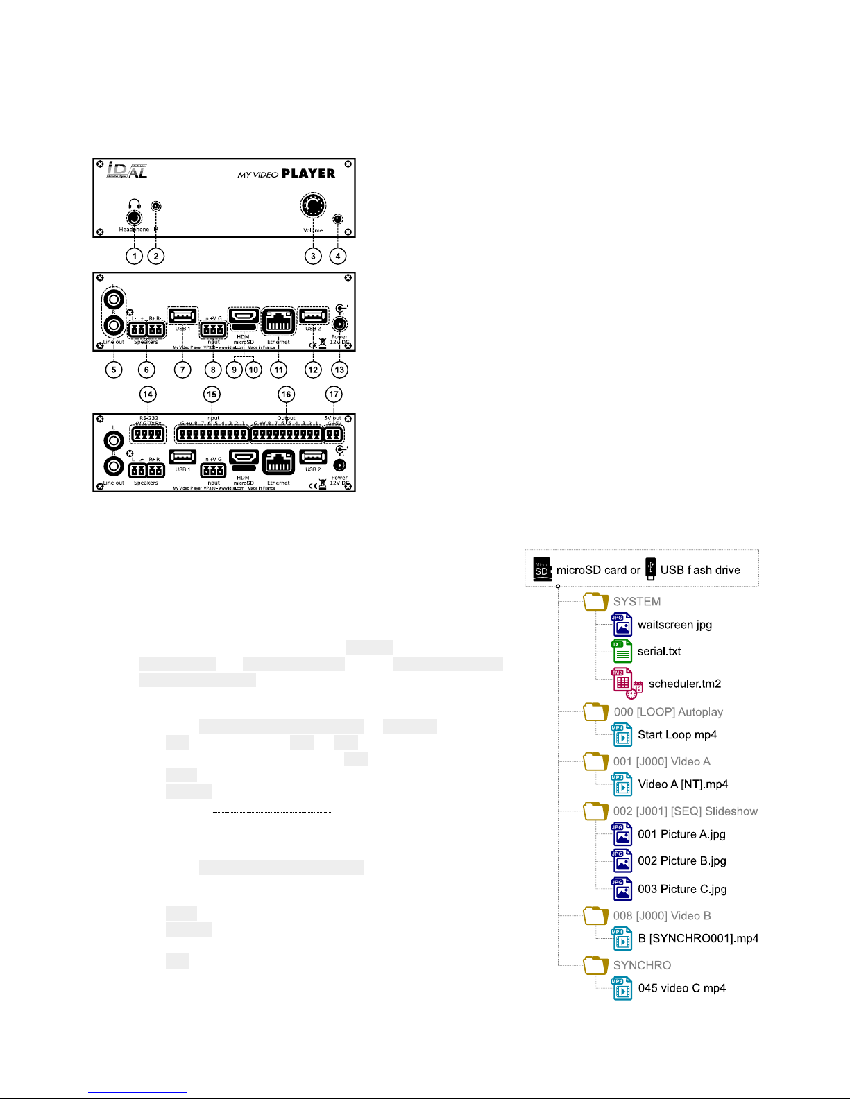
1 Headphone stereo audio output, standard 3.5 mm (TRS) jack
2 Infrared sensor
3 Clickable knob (volume)
4 Status LED
5 0 dBu line-level stereo audio output, RCA connectors
6 Class D amplified speaker stereo audio output, pluggable terminal blocks
7 USB Host 2.0 for USB flash drive, type-A receptacle
8 Standalone opto-isolated input and power supply output, pluggable terminal block
9 HDMI audio/video output, type-A (standard) receptacle connector
10 microSD card slot
11 10/100 Mbps Ethernet, RJ45 connector
12 USB Host 2.0 for USB flash drive, type-A receptacle
13 External DC power supply chassis socket
14 RS-232 serial link and power supply output, pluggable terminal block
15 8 opto-isolated input contacts and power supply output, pluggable terminal block
16 8 MOSFET outputs and power supply output, pluggable terminal block
17 5 V DC output, pluggable terminal block
This guide explains how to quickly start up the player for the first use. For the firmware, additional software and the
complete user guide of the product, see the support page of the My Video Player on www.id-al.com.
2 Preparation of the Storage Device
Choose a quality microSD card or USB flash drive, and format it as
FAT32. Store on it useful files according to the organization demanded
by the player (see given opposite example). Do not use special or
accented characters.
• Optional configuration files in the SYSTEM folder at the root:
serial.txt, scheduler.tm2, waitscreen.jpg,
maintenance.jpg, etc.
• Organization of the playback folders at the root:
° No subfolders allowed.
° Naming: xxx Name [TAG1][TAG2] or SYNCHRO
xxx: folder no. from 000 to 999 used by the commands.
The AutoPlay feature uses the 000 folder.
Name (optional): folder name (free).
[TAGx] (optional): tags controlling the playback. See the
chapter Folder and File Tags.
• Organization of the files in the playback folders:
° Format: MP4, MKV, MOV, WAV, MP3, M4A, OGG, JPG, PNG,
BMP and more.
° Naming: Name [TAG1][TAG2].ext
In sequential mode, the files are played in the
alphanumeric order.
Name: filename (free).
[TAGx] (optional): tags controlling the playback. See the
chapter Folder and File Tags.
ext: extension according to the file format.
© 2018, Waves System - 7 impasse de La Ville en Bois, 44830 Bouaye, France - Phone: +33 (0)2 40 78 22 44 - info@wsystem.com
ID-AL My Video Player - VP320 and VP330 - Quick Start Guide V1.0
3 Connection of the Input Contacts
The standalone input contact of the VP320 and the VP330 or the 8 input contacts of the VP330 are used to
generate events. Triggering devices can be connected to these inputs (e.g.: push-button, presence sensor, relay,
PLC, SensoPad, IRPad, etc.). These devices must behave like open or closed contacts between an input and the
ground of the player, the activation being triggered by a closed contact by default. The activation of the standalone
input contact generates a standalone event, and the activation states (1 if activated) of the input contacts of the
VP330 are combined to form a binary code identifying the generated event:
xxxcombination=Input1+
Input2×2+
Input3×4+
Input4×8+
Input5×16+
Input6×32+
Input7×64+
Input8×
128
A command is assigned to each event. By default, the standalone input and the xxx combination on the other
inputs trigger the playback of the folders 001 and xxx, respectively. The setup menu allows to change these
commands. With the VP330 and up to 8 combinations (001, 002, 004, 008, 016, 032, 064, 128), the triggering
devices can be directly connected to the inputs. Beyond, a circuit based on diodes can be used to obtain up to 255
combinations (e.g.: the board ID-AL Ext15In providing up to 15 combinations).
4 Connection of the Output Contacts
The VP330 offers 8 outputs with MOSFET switches (up to 500 mA per output) to operate power relays, motor
controllers, lights, players, and various devices. The states of the output contacts can be controlled by the
[RESxxxxxxxx] (applied at Start of playback) and [REExxxxxxxx] (applied at End of playback) folder and file tags.
xxxxxxxx represents the activation states of the 8 outputs, from the 8th to the 1st: a 0 opens the contact, a 1 closes it,
and a # keeps its last state. E.g., if 001[RES00001000][REE00000000] is the name of the folder 001, then the
4th contact is closed and all the other contacts are opened when the playback of this folder starts, and all the
contacts are opened when the playback of this folder ends.
5 First Startup
• Make sure that the player is off (mains adapter unplugged).
• Connect the video and audio outputs to the installation according to the needs.
• Connect the input and output contacts according to the needs. See the chapters Connection of the Input
Contacts and Connection of the Output Contacts.
• Connect the Ethernet network and the RS-232 serial link if needed.
• Insert the prepared storage device. See the chapter Preparation of the Storage Device.
• Turn the player on by plugging the mains adapter.
• Use the setup menu to configure the player. See the chapter On-Screen User Interface.
• The player is operational.
6 On-Screen User Interface
The on-screen information and menu, the clickable knob, and the infrared remote control are aimed at viewing the
player state, configuring it, and controlling the playback. The following controls are available:
Control Remote Control Key or Front Panel Control Description
Playback
Control the playback.
Custom ▄ ▄ ▄ ▄ Send a configurable order.
Volume VOL + VOL -
Clickable knob Change the volume.
Standby and wake up POWER Set the player to standby or wake it up.
Configuration MENU ESC OK Use the on-screen setup menu to configure the player.
7 Scheduler
The player can be programmed thanks to the Scheduler, according to a timetable provided on the storage device. It
manages the playback thanks to folder playback, stop and resume commands.
• The timetable is stored in a scheduler.tm2 file, to generate with the Scheduler software.
• Once the scheduler.tm2 file has been created, it must be placed in the SYSTEM folder of the storage
device as explained in the chapter Preparation of the Storage Device.
© 2018, Waves System - 7 impasse de La Ville en Bois, 44830 Bouaye, France - Phone: +33 (0)2 40 78 22 44 - info@wsystem.com
 Loading...