

Icy Box IB-RD3680SU3 Quick Installation Manual
1
3
2
6
IB-RD3680_Series_engl.ai 1 14.05.2014 09:28:18IB-RD3680_Series_engl.ai 1 14.05.2014 09:28:18
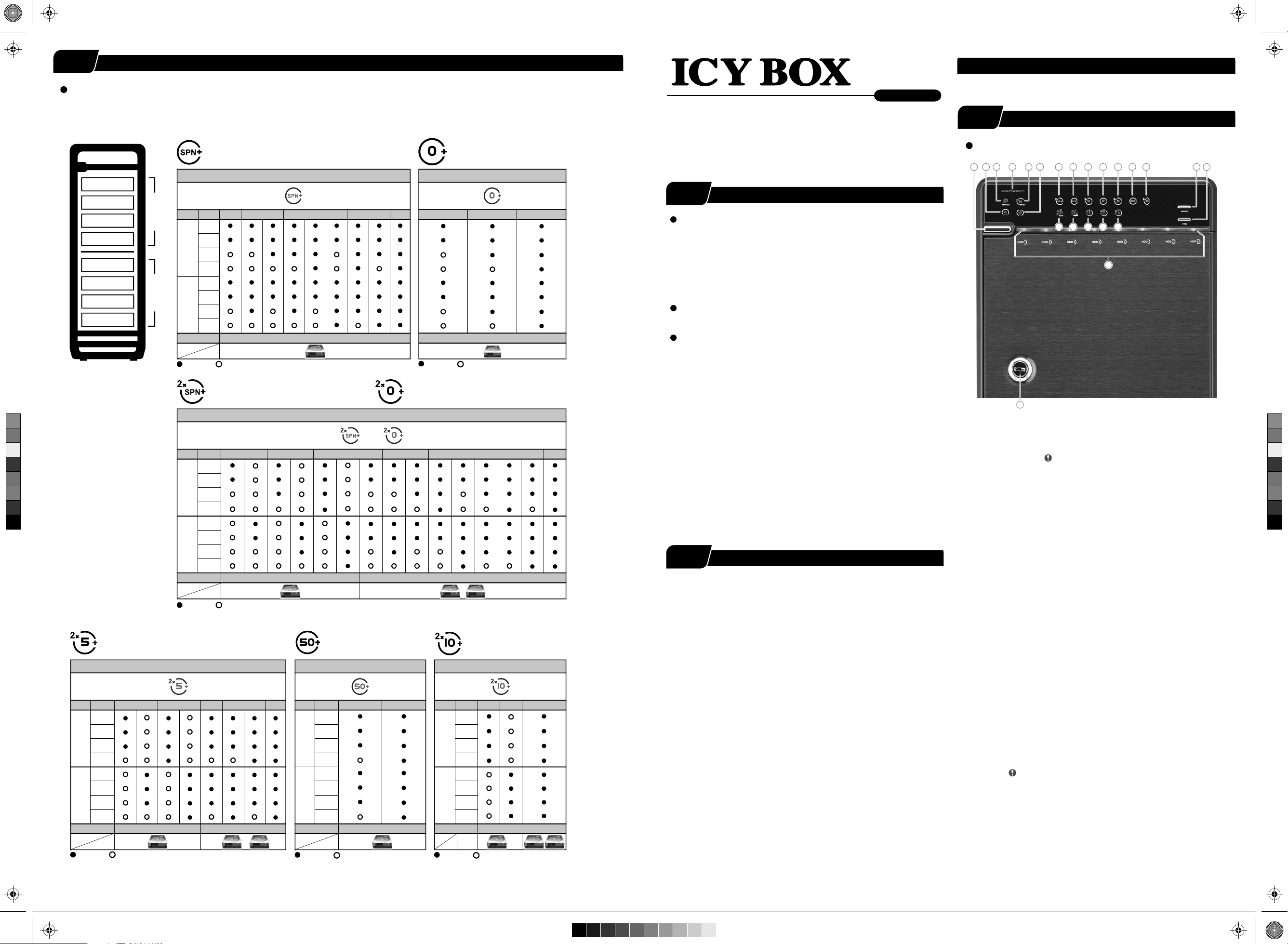
RAID mode setup
6
STEP
Please visit our website for latest manual
Set-up
First install the HDD from up to down in the enclosure. Power on the d ev i ce, press and hold RAID button f or 3 seconds until LED flashes.
Press it again, sele ct the R AID mode you want to use and press the Confirmation Butt on on the rear panel till th e d ev i ce shuts down.
Power the device on again and t he RAID mode setup is compl eted.
Spanning Mode (BIG)
(Layer 1 and layer 2 combined and shown as 1 HDD capacity icon)
RAID MODE
RA ID 0 (Striping Mo de)
(layer 1 and layer 2 combined and shown
as 1 HDD capacity icon)
RAID MODE
IB-RD3680SU3
8-bay external RAID enclosure
3.5’’ SATA I/II/III HDD
Quick Installation Guide
http://www.raidsonic.de
Front Panel Overview
3
STEP
LED Indication / Button
1 2 3 5 64
7
11 12 13 19 20
HDD 1
HDD 2
HDD 3
HDD 4
HDD 5
HDD 6
HDD 7
HDD 8
Layer 1 Layer 2
HDD No.
Layer
Layer 1
Layer 2
: Installed : Empty
4 HDDs 8 HDDs7 HDDs6 HDDs5 HDDs
1.
2.
3.
4.
5.
6.
7.
8.
Figure-1
4 HDDs
shown as 1 HDD capacity iconshown as 1 HDD capacity icon
: Installed : Empty
6 HDDs 8 HDDs
Figure-2
STEP
Operation System
Windows Vista (32bit/64bit) / Windows 7 (32bit/64bit)
Windows 8 (for PC version only)
(under MBR partition, supports total capacity up to 2 TB only)
Windows Vista (32bit/64bit) / Windows 7 (32bit/64bit)
Windows 8 (for PC version only)
(with GPT partition enabled , supports total capacity of more than 2TB)
Mac OS X 10.8 or later
Operation Environment
Temperature 0 ~ 50 °C Humidity 90 % RH
References
1.
Smart fan controlled by the built-in thermal sensor
and it comes with 2 modes (auto
Level 1: higher than 55 °C
2 X Spanning (BIG) 2 X RA ID 0 (Striping)
(layer 1 and layer 2 shown individually
as 1 or 2 HDD capacity icons)
C
M
Y
CM
MY
CY
CMY
K
Layer
HDD No.
1.
2.
Layer 1
3.
4.
5.
6.
Layer 2
7.
8.
: Installed : Empty
2 HDDs
shown as 1 HDD capacity icon shown as 2 HDD capacity icons
RAID MODE
or
(layer 1 and layer 2 shown individually
as 1 or 2 HDD capacity icons)
6 HDDs
7 HDDs 8 HDDs5 HDDs4 HDDs3 HDDs
Figure-3
Level 2: 45 °C ~ 54 °C
Level 3: below 45 °C
Support USB transfer speeds up to Super Speed (5 Gbit/s),
2.
eSAT A transfer speed (1.5~3.0 Gbit/s)
Changing the RAID mode will cause data lost.
3.
4.
Please refer to the instructions when switchi ng the RAID mode,
otherwise the execution might fail.
5.
Interface of US B / eSATA can not be used at the same tim e.
When using RAID function, HDDs with the same brand, model and
6.
capacity is strongly recommended.
7.
Under Windows Vis t a / 7, users can e nable G P T when init ializing
HDD with a total capacity of more than 2 TB.
STEP
• Follow all instructions.
• Do not place this device near water.
• Clean only with dry cloth.
• Do not block any ventilation openings.
2 X RA ID 5
(layer 1 and layer 2 shown individually
as 1 or 2 HDD capacity icons)
RAID MODE
RAID 50
(layer 1 and layer 2 combined
and shown as 1 HDD capacity icon)
RAID MODE RAID MODE
2 X RA ID 10
(layer 1 and layer 2 shown individually
as 1 or 2 HDD capacity icons)
• Install in accordance with the manufacturer’s instructions.
• Do not place near any heat sour c e s s u c h a s ra diat ors, heat registers,
stoves, or the devices (including amplifiers) that produce heat.
• Protect the power cord from being walked on or pinched particularly at
plugs, convenience receptacles, and the point where they exit from
Layer
Layer 1
Layer 2
HDD No.
3 HDDs 7 HDDs 8 HDDs6 HDDs4 HDDs
1.
2.
3.
4.
5.
6.
7.
8.
shown as 1 HDD capacity icon
shown as 2 HDD capacity icons
Layer
Layer 1
Layer 2
HDD No.
6 HDDs 8 HDDs
1.
2.
3.
4.
5.
6.
7.
8.
shown as 1 HDD capacity icon
Layer
Layer 1
Layer 2
HDD No.
4 HDDs 4 HDDs 8 HDDs
1.
2.
3.
4.
5.
6.
7.
8.
shown as 2 HDD capacity icons
the apparatus.
• Power supply cords shoul d b e ro ut e d s o th at th ey are n ot likel y to b e
walked on or pinched by items placed upon them or against them.
• Only use attachments/accessories specified by the manufacturer.
• Unplug this during lightning storms or when unused for long
periods of time.
• Refer all servicing t o qualified ser v ic e personnel. S e rvicing is re quired
when the devices has been damaged in any way, such as power-supply
cord or plug is damaged, liquid has bee n sp ille d o r o bje cts have fallen
into the devices, the devices has been exposed to rain or moisture,
does not operate normally, or has been dropped.
• Carefully read and follow the Quick Install Guide and User Manual.
• Do not drop or shake the device.
: Installed : Empty
Figure-4
Figure-5
: Installed : Empty: Installed : Empty
Figure-6
• Do not move the device when it is powered on.
• Do not overload wall outlets.
Brief Notes
1
2
Reminders
/ manual) and 3 levels of speed:
2,500rpm
1,800rpm
1,200rpm
~
3,500rpm
~
2,500rpm
~
1,800rpm
14
158169171018
21
22
Descriptions
Power butt on1.It needs to be pressed and held for 3 seconds
to power off.
This design prevents accidental power off.
eSATA in use / access
2.
3.
Rebuild
4.
Blue
Orange
HDD error When any of HDD1~HDD8 has error , HDD error is on.
5.
6.
2 x Spanning Mode (BIG)
7.
Spanning Mode (BIG)
8.
2 x RA ID 0 Striping Mode
9.
RA ID 0 Striping Mode
10.
2 x RA ID 5
11.
RAID 50
12.
2 x RA ID 10
13.
Smart Fan automatic mode
14.
Smart Fan manual mode
15.
Fan speed
16.
Fan speed
17.
Fan speed
18.
Mode RAID mode button needs to be pressed and held
19.
20.
Fan button
21.
HDD1 / HDD2 / HDD3 / HDD4 / HDD5 / HDD6 / HDD7 / HDD8
Blue
Purple
Red
22.
Key slo t
Power on
Sleep mode
in use / acce ssUSB
level 1
level 2
level 3
for 3 seconds to switch the device's RAID mode.
This design will preve nt accidental execution of this fun ction.
Controls auto & manual modes and fan speed from
level 1 to level 3.
active
access
rebuild
HDDHDD
22
HDDHDD
33
HDDHDD
44
4
5
IB-RD3680_Series_engl.ai 2 14.05.2014 09:28:27IB-RD3680_Series_engl.ai 2 14.05.2014 09:28:27
4
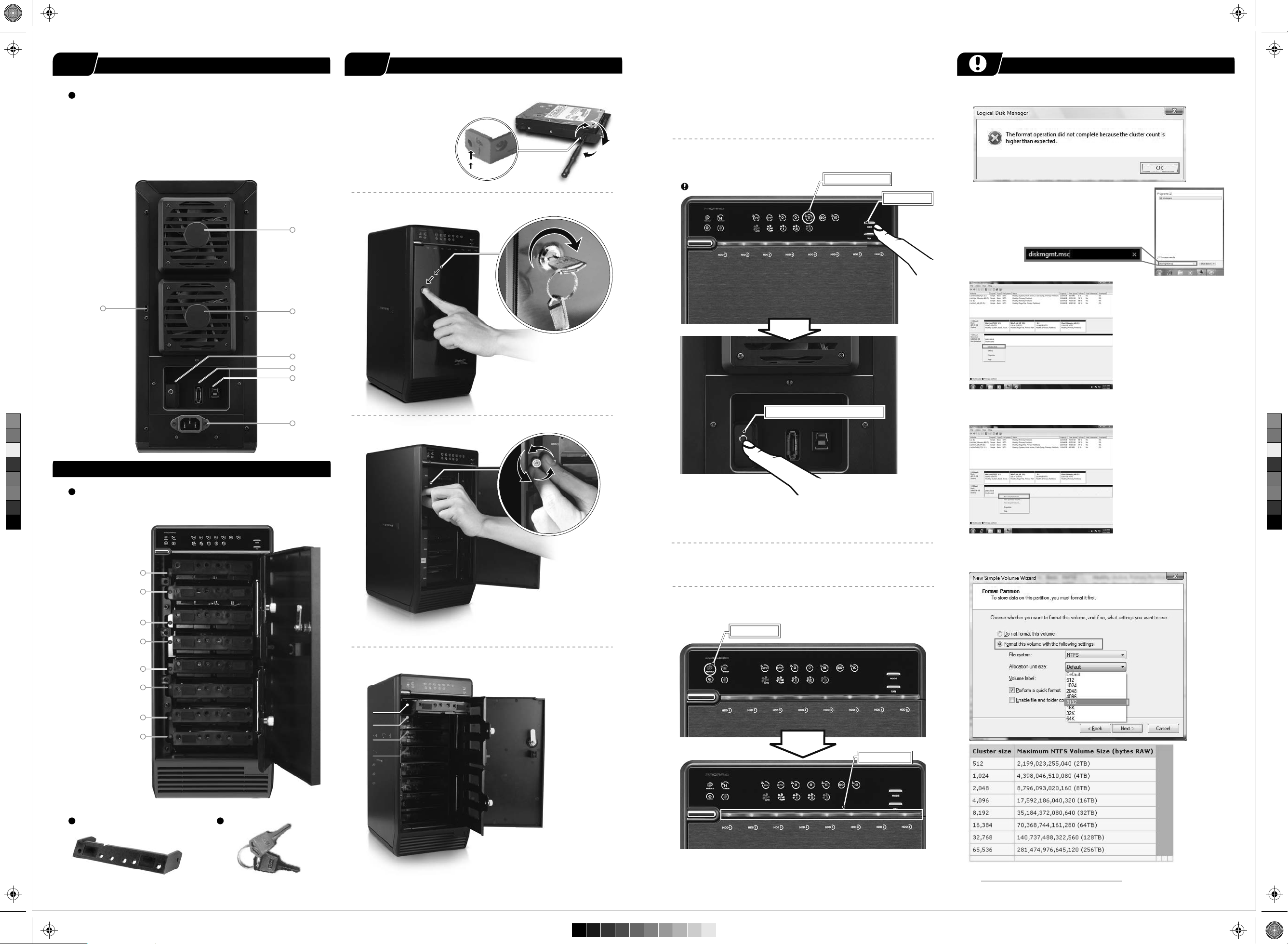
STEP
Rear Panel
Descriptions
1.
Fan
1.
2.
RAID Mode confirmation button
eSATA port
3.
USB 3.0 port
4.
5.
220 V AC Input port
6.
Kensington
hole
Rear Panel Overview
6
Quick Installation Guide
5
STEP
Please use the provided screws to secure the handles
a.
to the HDDs.
Close and secure the covers.
e.
Plug in USB or eSATA cable.
f.
Under Windows Vista (32/64-bit) / Windows XP (64-bit),
if the total capacity is m ore than 16 TB.
Trouble Shooting
RAID mode setup, users need to press and HOLD the "RAID" button for
3 seconds t ill the LED flashes, press again to change the mode.
g.
Defaut Setting at ”RAID 5” mode.
Orange / RAID 5
b.
Unlock the cover with the key supplied and pre ss the curricular
depress i on to open the cover.
1
Mode button
If the HDD is uninitialized, you may have to initialize
it by doing step s as followed:
At first click “Start”, “Execute” at your PC
and key in “diskmgmt. msc”.
After th at please press “Enter” key.
1. Start disk initializati o n.
1
2
3
4
Note: Please enable GPT if the total capacity is more
than 2TB and enable MBR if the total capacity is less than 2TB.
C
M
Y
CM
MY
CY
CMY
K
Inside Overview
Inside Panel
Descriptions
HDD1 Error
1.
1.
2.
HDD2 Error
HDD3 Error
3.
HDD4 Error
4.
HDD5 Error
5.
6.
HDD6 Error
HDD7 Error
7.
HDD8 Error
8.
1
2
3
4
5
c.
Release the inner covers anti-clockwise!
After s electing th e RAID you want, p ress and HOLD the confirmation
button in th e rear panel till the dev i ce shuts down.
Initialize the HDD accordingly to your operating system.
h.
i.
Rebuild time varies depending on the HDD volume, say about 1 hour for
200GB.
Red / rebuild
RAID Mode Confirmation button
2. Create new partition and format disk.
Under Windows Vista (32/64-bit) / Windows XP (64-bit),
if the total capacity is more than 16 TB, it's strongly r ecommend to
choose “Allocat i on unit size” at 8192 when formatting the HDD.
HDD Handle
d.
Install the HDD s f rom up to down. Please refe r STEP 6 for detail s .
5
6
7
8
HDD 1
Blue / active
Keys
When rebuild completes, rebuild LED goes off.
Users could find more infor m at i on about clust er allocation
at:http://support.micr osoft.co m/kb/302873
 Loading...