

Page 1
Page 2

TableofContents
GENERALINFORMATION......................................................................................................................4
COPYRIGHT............................................................................................................................................................4
NOTICESANDCLASSIFICATIONS.................................................................................................................4
CONTACTUS..........................................................................................................................................................4
INTRODUCTION........................................................................................................................................6
FEATURES..................................................................................................................................................................6
SYSTEMREQUIREMENT...........................................................................................................................................7
PC...................................................................................................................................................................................7
MAC...............................................................................................................................................................................7
OPTIONALACCESSORIES.........................................................................................................................................7
PACKAGECONTENTS...............................................................................................................................................7
SYSTEMUNITVIEWS............................. ............................................................................. ....................8
FRONTVIEW.............................................................................................................................................................8
REARVIEW................................................................................................................................................................8
TOP&COVERVIEW(EXPOSED)...........................................................................................................................9
INSERTING/REPLACINGTHEHARDDRIVESINTHERAIDSYSTEM....................................10
CONNECTINGTHERAIDSYSTEMTOACOMPUTER..................................................................16
CONNECTINGMULTIPLEDEVICES......................................................................................................................18
RAIDMODES................................ .............................................................................. .............................19
RAID0(STRIPING)..............................................................................................................................................20
RAID1(MIRRORING).........................................................................................................................................21
JBOD.......................................................................................................................................................................22
SETTINGTHERAIDMODE(MANUALLY)......................................................................................23
RAIDSWITCH........................................................................................................................................................24
HDDSLOTNUMBER.............................................................................................................................25
HDDALLOCATION................................................................................................................................25
LEDINDICATORS..................................................................................................................................26
POWERLEDX1....................................................................................................................................................26
HDDLEDX4........................................................................................................................................................26
SAFEREMOVALOFTHERAIDSYSTEM.........................................................................................27
EXTERNALBOOTUP.............................................................................................................................28
PC.................................................................................................................................................................................28
MAC.............................................................................................................................................................................28
DiskVolumeOver2TB........................................................................................................................................28
ESATAPCIEXPRESSCARDINSTALLATION..................................................................................29
SYSTEMREQUIREMENTS......................................................................................................................................29
HARDWAREINSTALLATION.................................................................................................................................29
DRIVERINSTALLATION........................................................................................................................................30
VERIFYDRIVERINSTALLATION..........................................................................................................................30
MacOS:......................................................................................................................................................................30
WindowsOS:...........................................................................................................................................................30
Windows2003andXP:......................................................................................................................................31
Page 3

Windows2000:......................................................................................................................................................31
Q&AS.........................................................................................................................................................32
GENERAL.................................................................................................................................................................32
HDDCAPACITY.....................................................................................................................................................32
DISCREPANCYINREPORTED&ACTUALSIZECAPACITY................................................................................33
HDDALLOCATION................................................................................................................................................33
RAID0...................................................................................................................................................................34
JBOD.......................................................................................................................................................................34
APPENDIX:SPECIFICATIONS............................................................................................................35
Page 4
GENERAL INFORMATION
COPYRIGHT
Copyright @ 2010 Raidsonic Technology GmbH. All rights reserved. No part of
this publication may be reproduced, stored in a retrieval system, or transmitted in
any form or by any means, electronic, mechanical, photocopying, recording or
otherwise, without the prior written consent of Raidsonic Technology GmbH.
The product information provided in this manual is subject to change without
prior notice and does not represent a commitment on behalf of the vendor. The
vendor assumes no liability or responsibility for any errors that may appear in this
manual.
NOTICES AND CLASSIFICATIONS
FCC-B Radio Frequency Interference Statement
This device complies with Part 15 of the FCC rules. Operation is subject to the
following two conditions:
This device may not cause harmful interference.
This device must accept any interference received, including interference that
may cause undesired operation.
This equipment has been tested and found to comply with the limits for a
Class B digital device, pursuant to Part 15 of the FCC rules. These limits are
designed to provide reasonable protection against harmful interference when the
equipment is operated in a commercial environment. This equipment generates
uses and can radiate radio frequency energy and, if not installed and used in
accordance with the instruction manual, may cause harmful interference to radio
communications.
CONTACT US
We are committed to offer economical, high-quality connectivity and storage
enclosure solutions to the market. Your questions, inquiries or comments are
welcomed. For Technical Support, please go to our website at
www.raidsonic.de
RaidSonic Technology GmbH
Kurt-Fischer-Str. 50
22926 Ahrensburg
Germany
Page 5

PRECAUTIONS FOR THE RAID SYSTEM
♦ The main circuit board of the RAID System is susceptible to static
electricity. Proper grounding is required to prevent electrical damage to
the RAID System unit or other connected devices, including the host
computer. Always place the RAID System unit on a smooth surface and
avoid all dramatic movement, vibration and percussion.
♦ Do NOT allow water to enter the RAID System unit.
♦ Installation of additional equipment in the host computer may be required.
Visit our website to download the latest product information updates.
♦ Do NOT attempt to service this unit yourself. Disassembling the RAID
System’s inner parts will expose you to dangerous voltages or other
hazards.
♦ Do NOT block the ventilation. Proper airflow is required to ensure reliable
operation and to prevent overheating.
♦ Do unplug the RAID System unit from the electrical outlet when not in use
to provide an ecological friendly environment.
♦ Use only the power supply cable provided with the RAID System unit.
Page 6
INTRODUCTION
Thank you for purchasing the ICY BOX 3.5” SATA HDD 2-bay RAID System.
The ICY BOX 3.5” SATA HDD 2-bay RAID System provides massive storage
capacity and advanced RAID configuration options in a desktop storage device.
The RAID Mode Switch allows easy configuration of RAID 0 (Striping), RAID 1
(Mirroring), and JBOD (Just a Bunch Of Disks) RAID modes.
Please thoroughly read and follow the instructions provided in this manual.
Failure to do so may result in damage to the RAID System, and any or all of the
connected devices.
Features
Supports current SATA II compliant HDDs, fully backward compatible with
SATA 1.0 and SATA 1.0a compliant HDDs
Connects flexibly via an eSATA, USB 2.0, 1394a or 1394b port
Provides RAID 0 (Striping), RAID 1 (Mirroring), and JBOD (Just a Bunch
Of Disks) for effective storage management
Configures RAID modes easily using switches, no IT expertise required
Simplifies RAID management, no software installation required
Monitors system status via LED indicators
Prevents over-tightened HDDs with auto-limiting segmented screws
Features a trayless function with the SmartGuider and the user-friendly
design enables effortless HDD hot-swapping
Dissipates heat efficiently with aluminum housing
Maximizes airflow with silent fans and mechanical designs
Supports hot-plug and HDD hot-swap
Supports both online and offline rebuild
Any loss, corruption, or destruction of data is the sole responsibility of the
user of the RAID System. Under no circumstances will the manufacturer be held
liable for the recovery or restoration of any data.
SmartGuider is a trayless device that utilizes the simplicity of a handle and
screws. The integrated handle is attached to the HDD with auto-limiting
segmented screws. Then, the entire setup can be slide into the unit by aligning
the screws with the specially designed guides. This enables flexibility in removal
and insertion of the HDDs with ease.
Page 7
System Requirement
To use the 2-Bay RAID System, the minimum system configuration in the host
computer require the following:
PC
266MHz or faster CPU (Windows Vista requires a minimum 800MHz CPU)
64MB of RAM (Windows Vista requires 512MB of RAM)
Microsoft Windows 2000, XP, 2003, or Vista
One available eSATA port, USB 2.0, IEEE 1394a, or IEEE 1394b port
(Depend on model)
MAC
Macintosh PowerPC or Intel Core Duo processor
64MB of RAM (Mac OS X 10.4 requires 256MB of RAM)
Mac OS X 10.2 or higher (PowerPC) or Mac OS X 10.4 (Intel) or higher
One available eSATA port, USB 2.0, IEEE 1394a, or IEEE 1394b port
(Depend on model)
3.5” SATA compatible hard drive is required for the RAID System. Once the
HDDs are formatted, the actual available storage capacity can vary depending on
the selected operating environment (normally 5-10 % less).
Optional Accessories
eSATA PCI, PCI-X, or PCI-Express Card
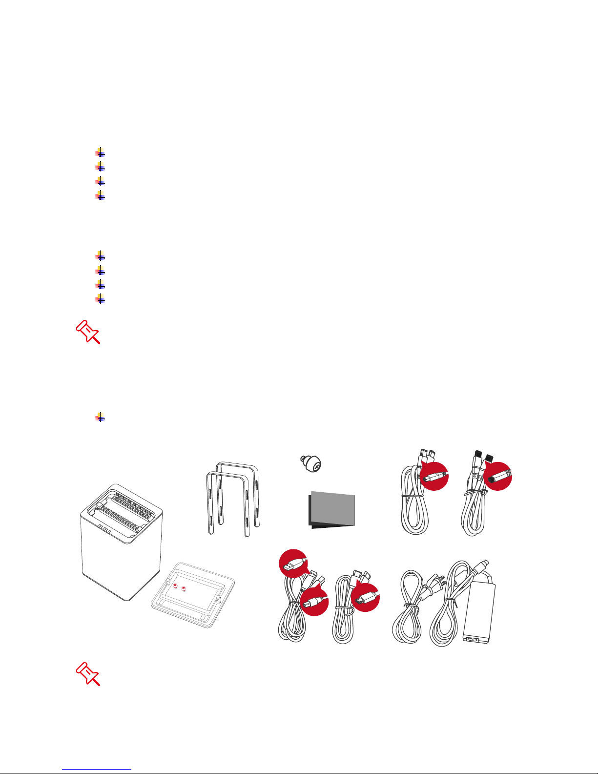
Package Contents
RAID System unit
2 Handles
2 spare HDD screws
provided on back part of
cover lid
USB Type B to
A Cable
Please keep all package contents and packaging material in the event that
the product must be returned.
HDD screws x 8
Quick Start Guide
eSATA Cable
FireWire 800 Cable
FireWire 400 Cable
External Power Supply
Page 8
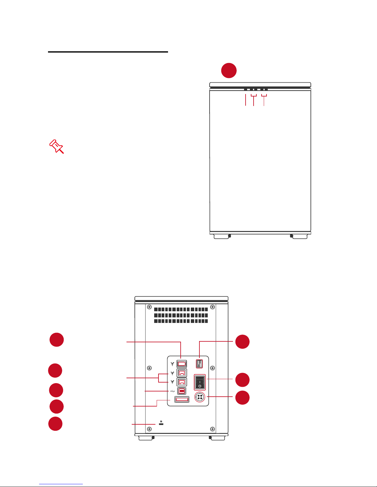
SYSTEM UNIT VIEWS
Front View
The status
indication of each
LED indicator is
listed under the
LED INDICATORS
section.
LED Indicators
1
Power
HDD2
HDD1
Rear View
2
FireWire 400
FireWire 800
3
(2 ports)
4
USB 2.0 Type B
eSATA Port
5
Lock Slot/Port
9
RAID Mode Switch
6
RAID
Power Switch
7
eSATA
DC IN
8
DC IN
Page 9
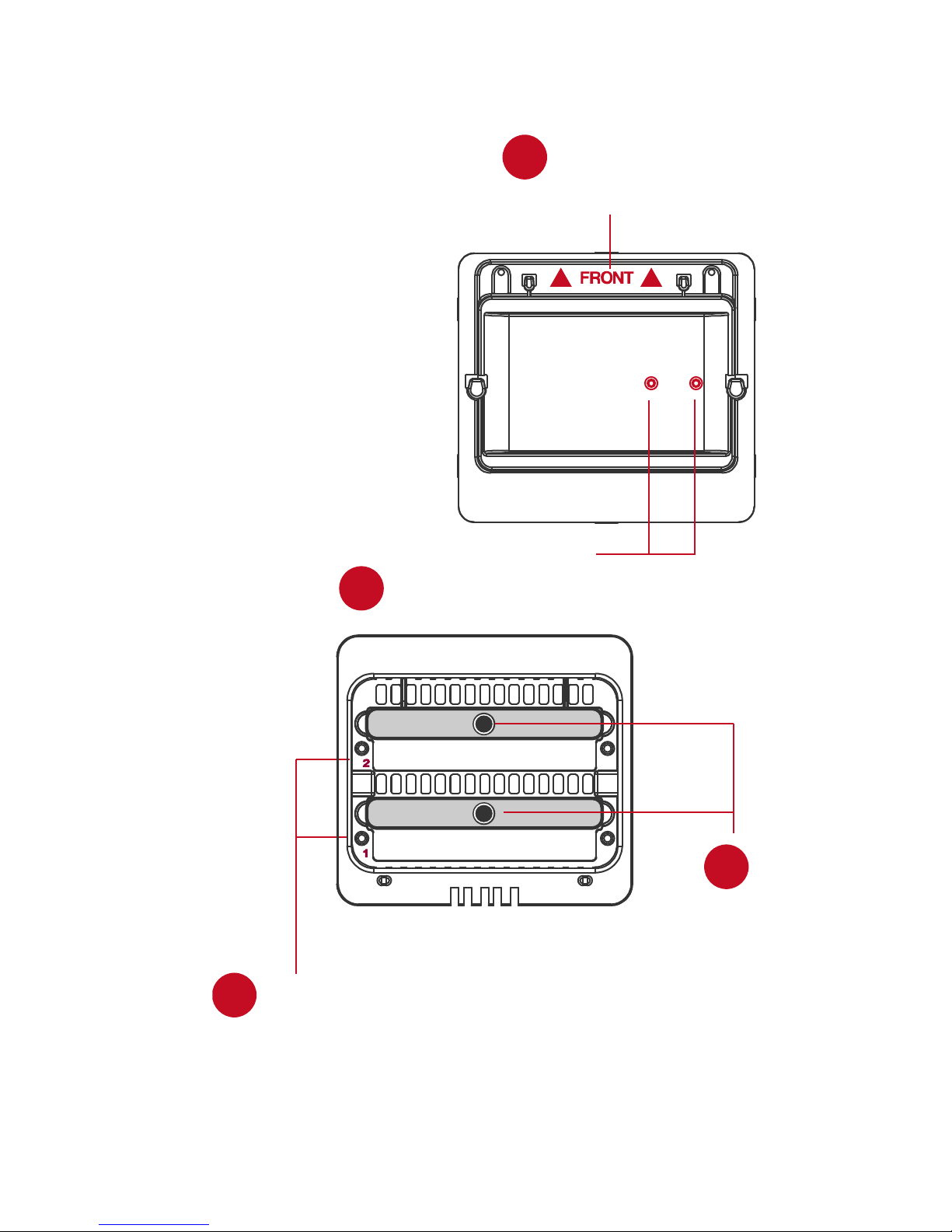
Top & Cover View (Exposed)
10
“Front” Indicator
9
11
2 Spare HDD Screws
12
2
1
HDD Slots
(indicate s HDD 1
through HDD 2)
13
Handles
Page 10
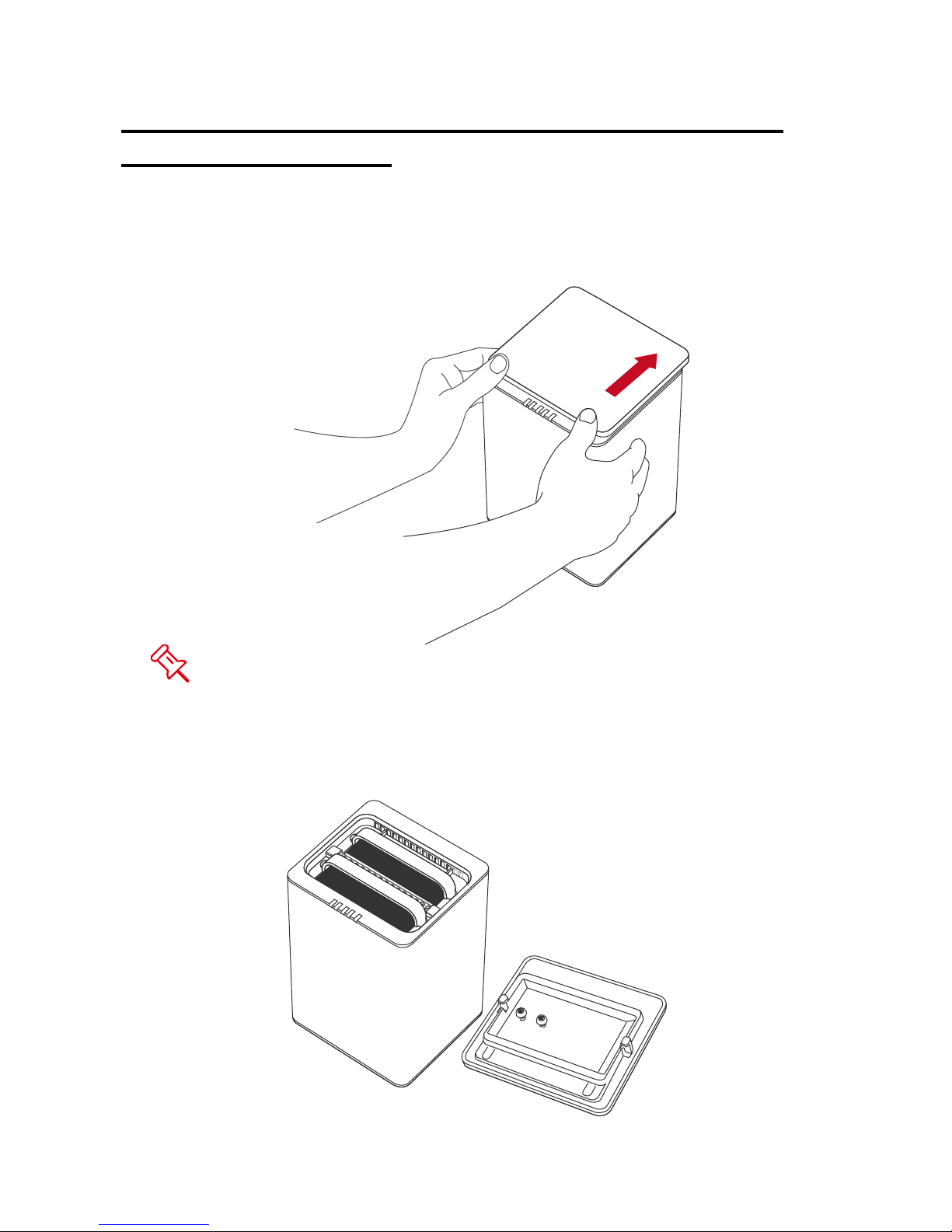
INSERTING/REPLACING THE HARD DRIVES IN
THE RAID SYSTEM
1. Place the RAID System with its front view facing you. Position both hands on
the front edge. Simultaneously, push the lid in the direction away from you,
front to back, using your thumbs.
A “click” sound would indicate the release of the top lid security clasp.
2. Lift the top lid up to remove and expose the top view (or HDD slots). Take out
the handles from the enclosure itself and locate the HDD screws in the
packaging box.
Page 11
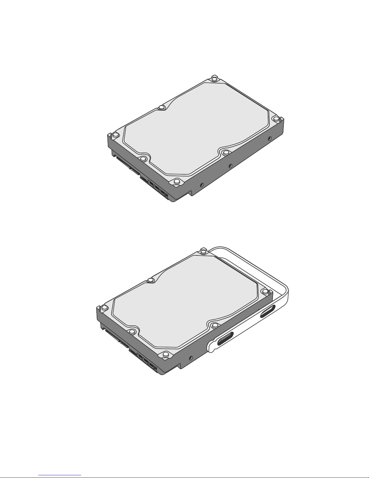
(Fasten the Handles on HDDS)
3. Place the HDD with the metal cover side facing up and ensure that the
interface connectors are oriented toward your left side.
Connectors
4. Position the handle to the HDD end, which is facing away from the interface
connectors, and align it with the screw hole openings.
Connectors
Page 12
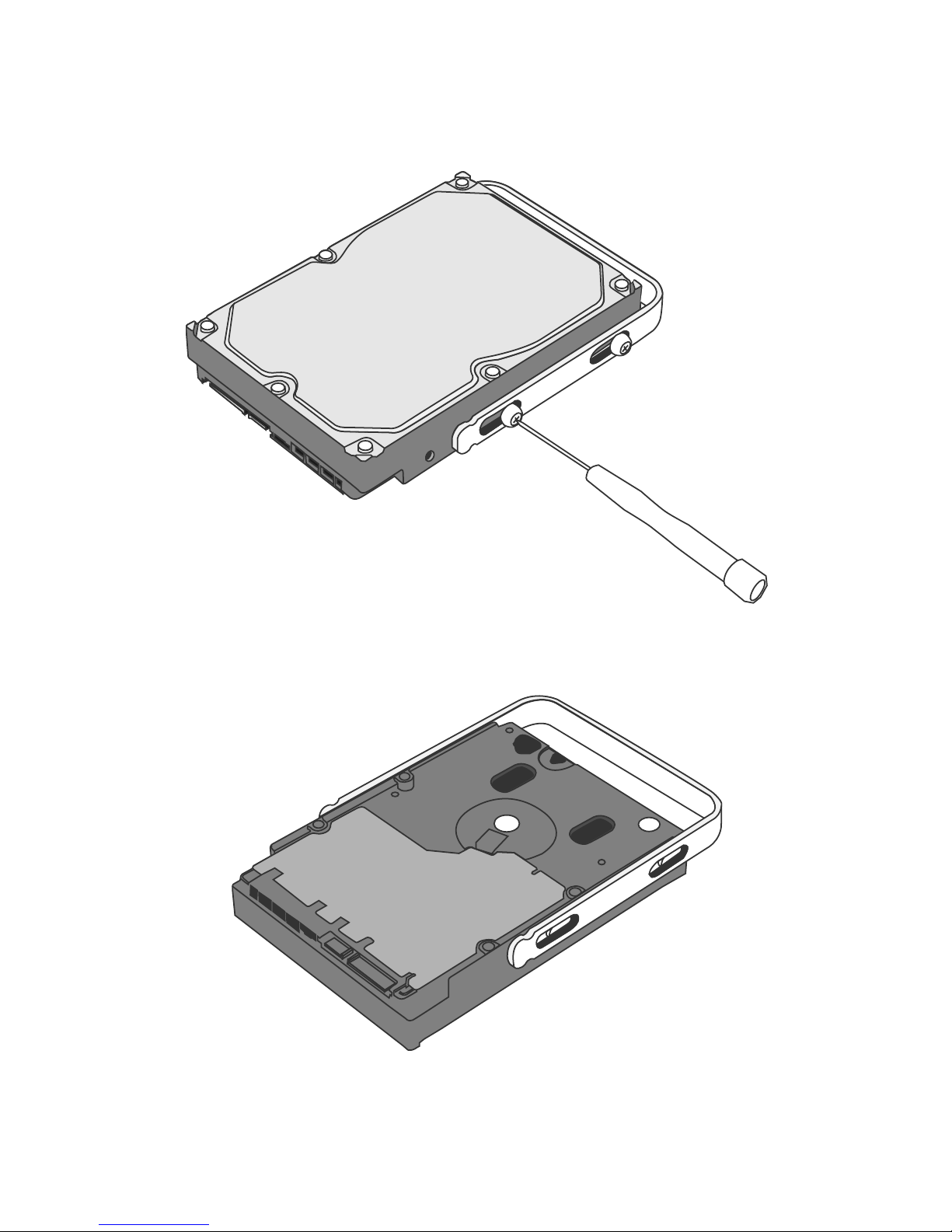
5. Fasten the handle onto the HDD by inserting and tightening the screws, the
left one first, then the right one.
Right
Left
6. Now, flip the HDD so it is facing you with the PCBA (Printed Circuit Board) on
top and the unfasten handle side facing you.
Page 13

7. Insert and tighten the screws, the left one first, then the right one.
Right
Left
8. Finally, test sliding the handle to make sure the holes glide smoothly on the
screw guides. Repeat the same procedures for the second HDD.
The auto-limiting segmented screws are designed to prevent the HDDs
or/and the handles from damages due to over-tightening. Furthermore, this
design makes the handle slide easily without any tightness.
Page 14
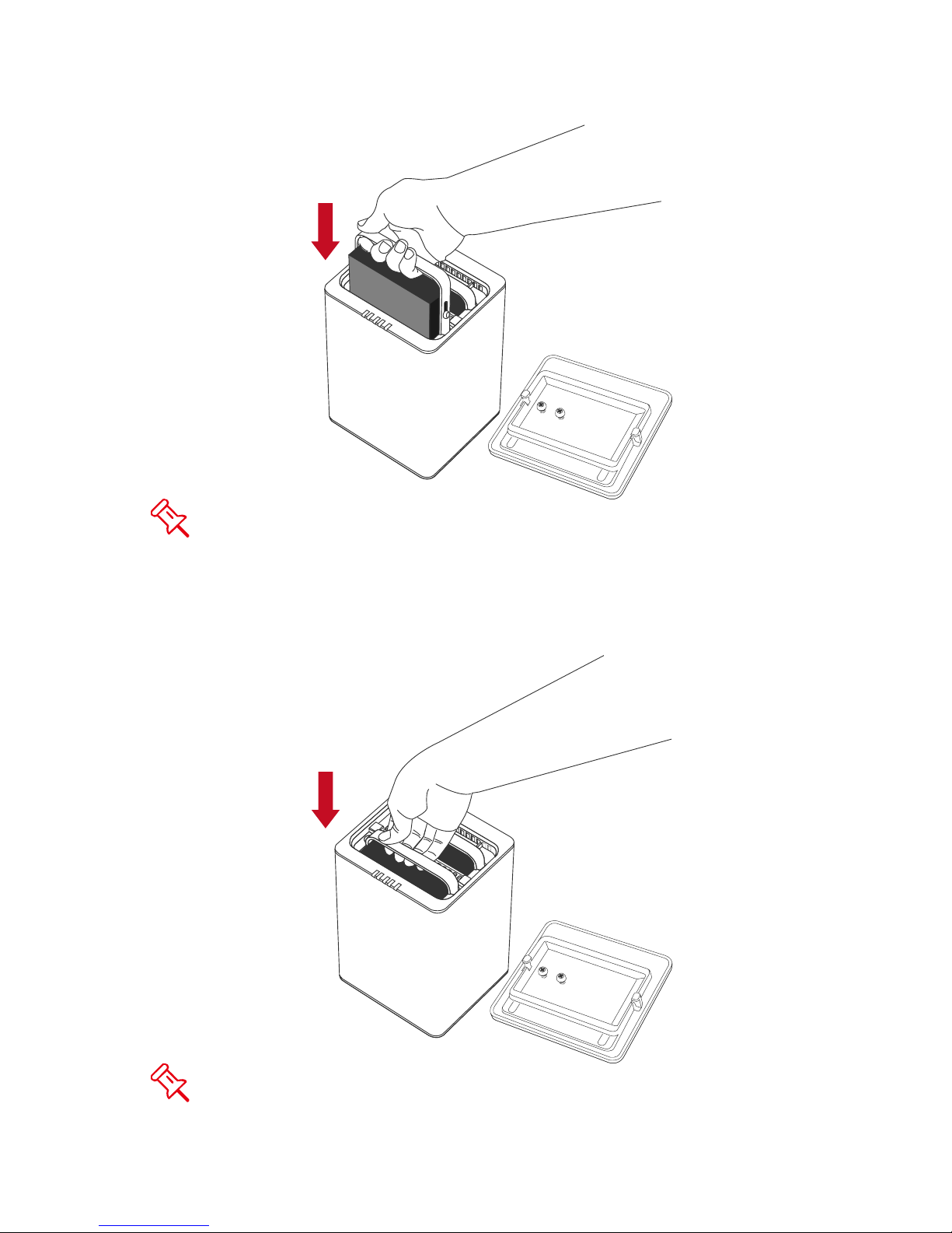
9. Hold the HDD with the metal cover side facing you and the handle attached
on the upward position.
When inserting the HDD on its reverse side, the SmartGuider System
won’t be able to align and the HDD cannot be inserted.
10. Align the handle with the guide rails and slide the HDD into the indicated slot.
Firmly push downward until a “thump” sound is heard. Repeat the same
procedures for the second HDD.
In most cases, you would need to firmly push the HDDs to a close until a
“thump” sound is heard.
Page 15
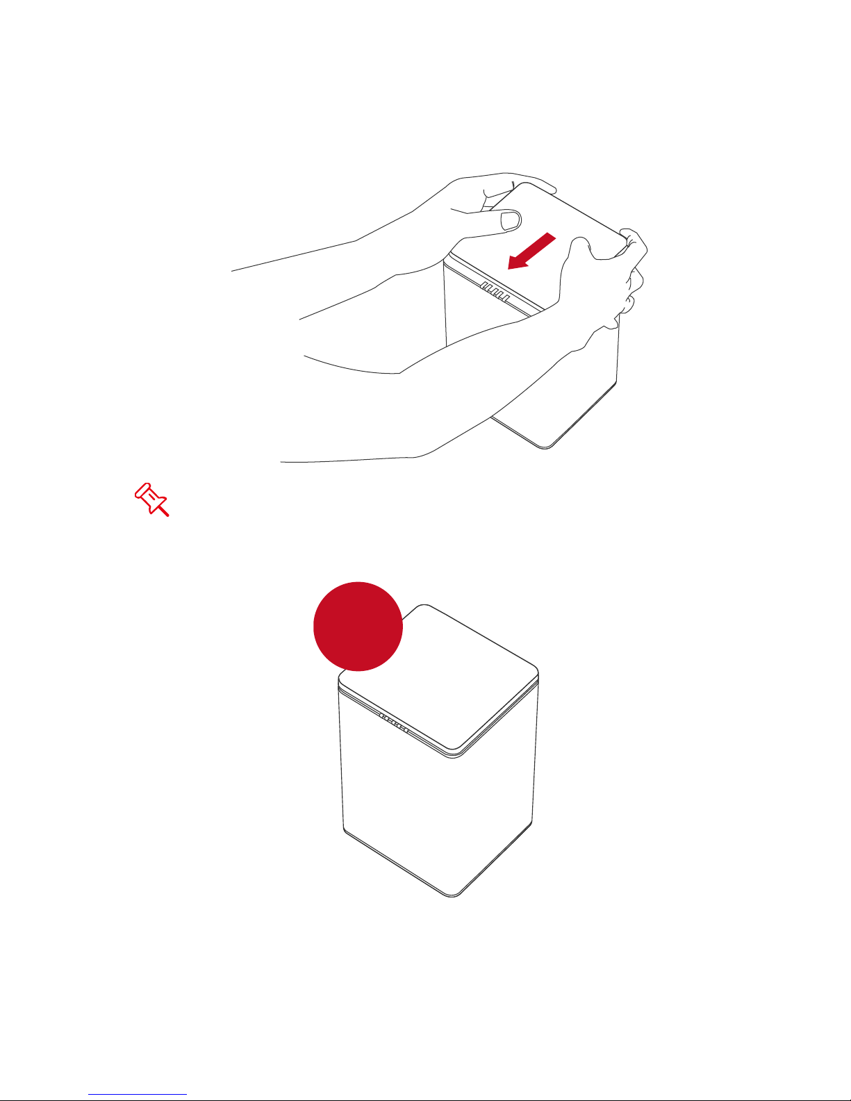
11. Place the RAID System with its front view facing you and the top lid on.
Position both hands on the back edge of the top lid. Simultaneously, push the
lid firmly downward and toward you, back to front.
A “click” sound would indicate grasp of the top lid security clasp.
12. Now, the RAID System is ready for connection to a computer!
Installing
HDDs OK!
Page 16
CONNECTING THE RAID SYSTEM TO A
COMPUTER
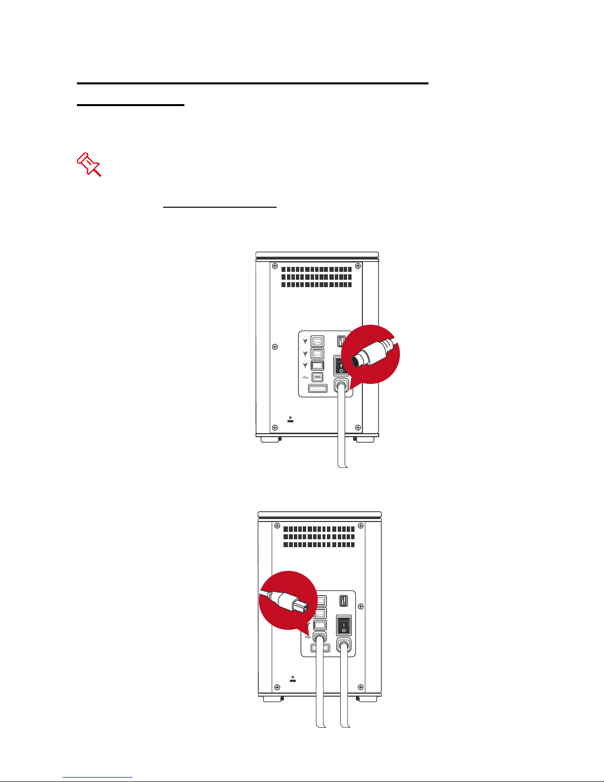
Complete the following steps to connect the RAID System to a host computer.
The RAID System should only be connected to a host computer via one
interface. Connection of the system to a computer via two or more interfaces
simultaneously is not recommended
1. Connect the AC/DC power adapter.
.
RAID
DC IN
eSATA
2. Insert both ends of the USB 2.0, eSATA, FireWire 400, or FireWire 800
cable(s) into the corresponding port of the RAID System and the host.
RAID
DC IN
eSATA
Page 17
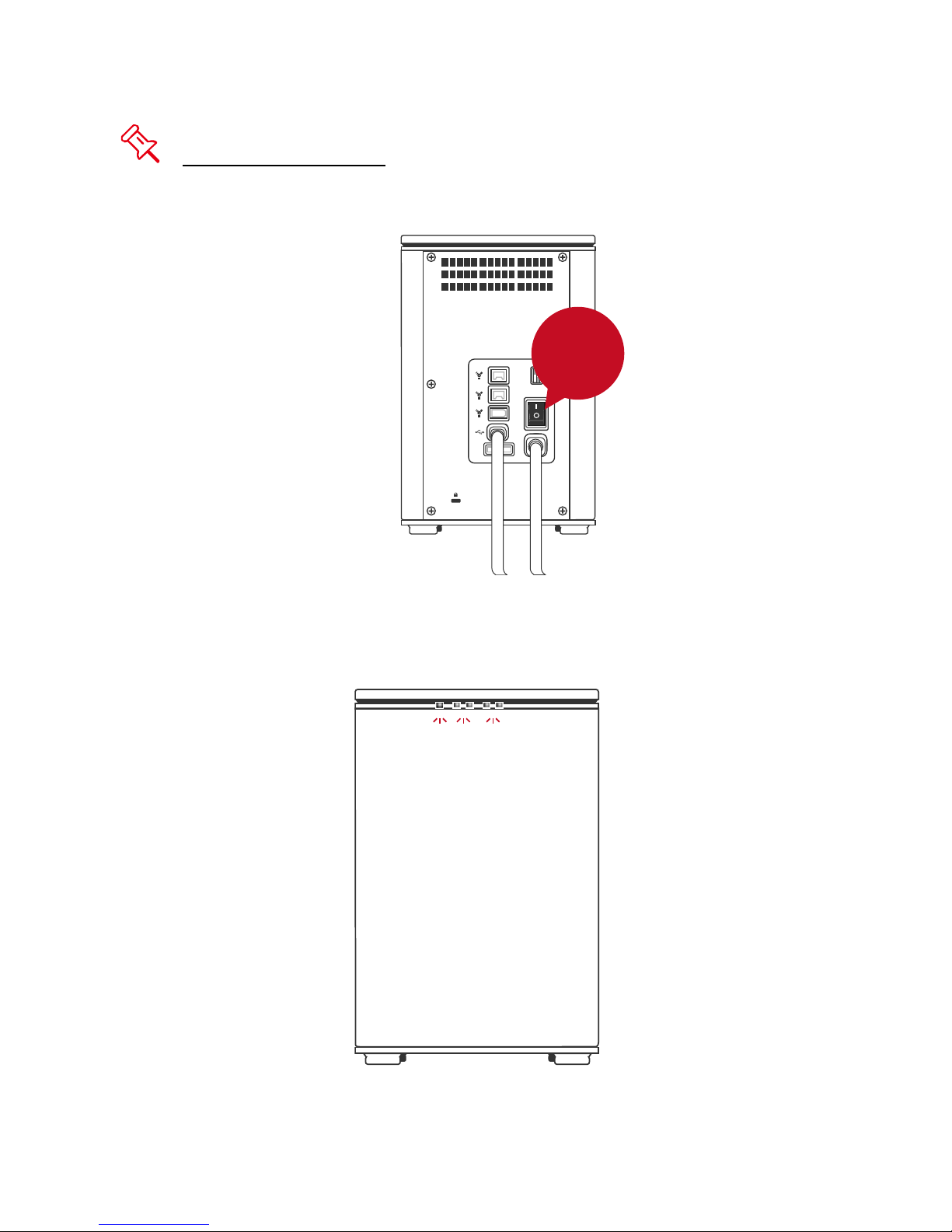
It is highly recommended to select only one interface to do data transfer.
3. Turn the power switch to the “on” position.
ON
RAID
DC IN
eSATA
4. When connected, the Power LED light will become steadily green, and the
HDD LED lights will become white and blink about 15 seconds. If the HDDs
are inside the RAID System, the HDD LED lights will remain steadily white. If
there are no HDDs inside the RAID System, the HDD LED lights will turn off
after blinking.
Page 18

5. You are now ready to begin using your RAID System!
Ready to
GO!
Due to compatibility issues, if you use the eSATA interface to do the data
transfer, the Silicon Image eSATA host controller is highly recommended.
Connecting Multiple Devices
Using FireWire 400 or 800, you can connect other computer hardware or digital
devices to your RAID System. This connection is called “Daisy chain”. Items
connected to the RAID System may be such as digital video camera, another
HDD, DVD writer, and much more. However, you must use the same interface in
order for the Daisy Chain to work. The computer will not recognize different
interfaces if they are all used at the same time. In addition, if a mix of
connections is used, the resulting speed will be limited to the lowest one
available.
When an additional FireWire connector is plugged in, the connector will be
viewed as a “daisy chain” port. When an additional USB or eSATA connectors is
plugged in, the connector will be viewed as its originate port, either USB or
eSATA respectively.
Page 19
RAID MODES
A Redundant Array of Independent (or Inexpensive) Disks (RAID) is a system
that utilizes multiple hard drives to share or replicate data among the disks. The
benefit, depending on the selected RAID Mode (combinations of disks), is one or
more of increased data integrity, fault-tolerance, throughput or capacity when
compared to single drives.
Deleting the current partition prior to changing RAID modes is highly
recommended.
Using identical HDDs with the same capacity and RPM, and from the same
manufacturer are highly recommended
for best capacity utilization.
Page 20
RAID 0 (Striping)
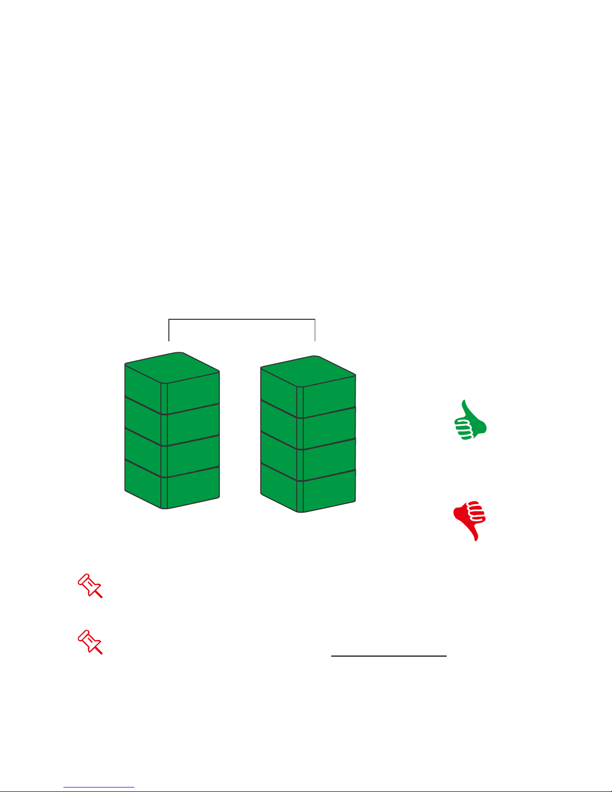
RAID 0 (Striping) is a performance-oriented, non-redundant data mapping
technique. It combines multiple hard drives into a single logical unit. Instead of
seeing several different hard drives, the operating system sees only one large
drive. Striping splits data evenly across two or more disks simultaneously,
dramatically increasing performance.
Striping can be implemented in disks of differing sizes, but the storage space
added to the array by each disk is limited to the size of the smallest disk.
Although Striping is an easily implemented and simple configuration, Striping
should never be used for mission critical applications. The speed of operation is
fast in comparison to other RAID modes.
RAID 0
SIZE
A1
B1
C1
D1
Disk 1
In Striping mode, if one disk in the RAID System fails, all data in both
installed disks will be lost.
When operating under Striping mode, it is not recommended to do HDD Hot
Swap. Any attempt to do so may result in complete loss of all data.
Disk 2
A2
B2
C2
SAFE
D2
Page 21
RAID 1 (Mirroring)
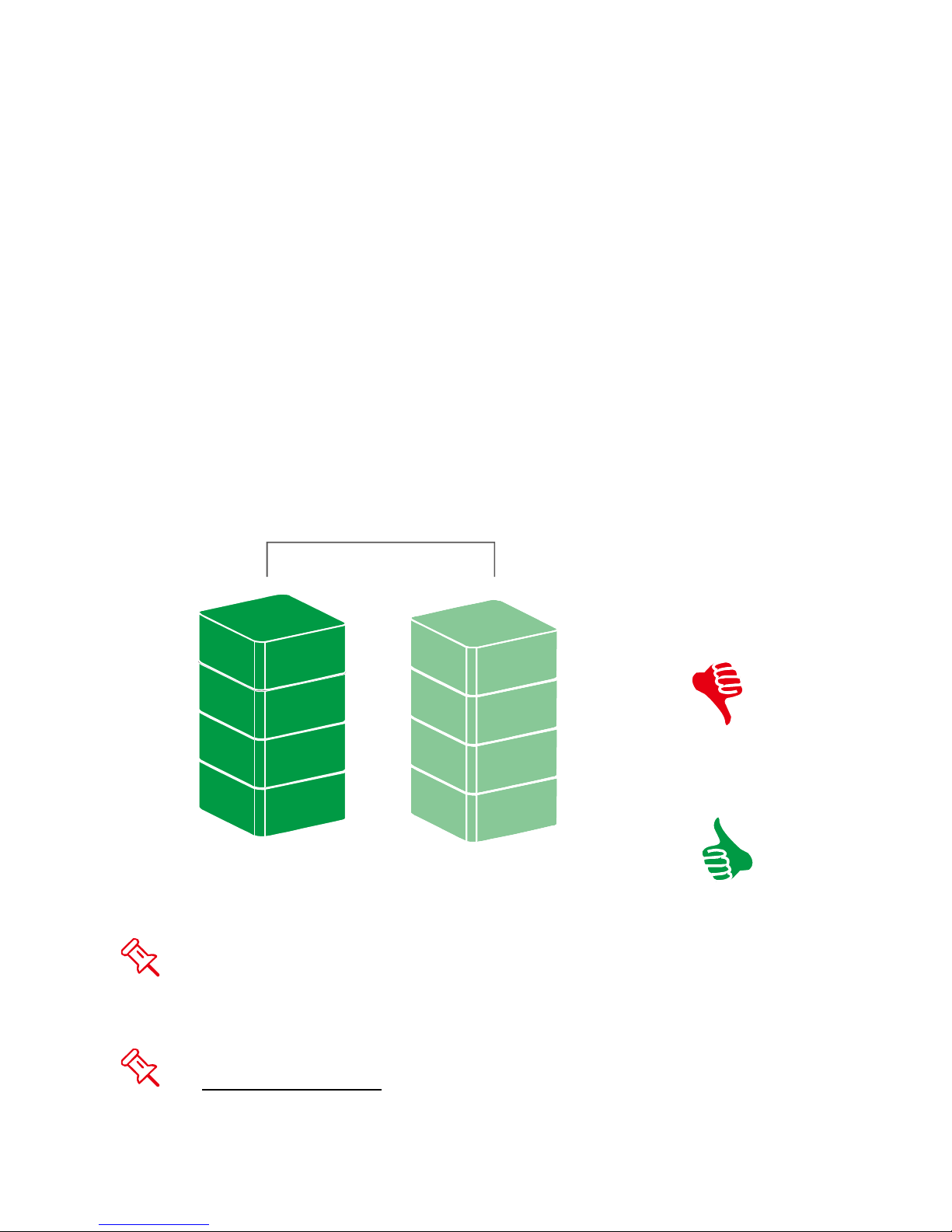
Mirroring (RAID 1) consists of at least two drives storing duplicate copies of the
same data. In this mode, the data is simultaneously written to two disks. Thus,
the storage capacity of a two-disk array is combined into a single disk and the
capacity is limited to the size of the smallest disk. The speed of the operation is
very slow in comparison to other RAID modes.
During rebuild, the first HDD inserted into one of the HDD slots and is recognized
by the RAID System as the source HDD. To rebuild existing data from a source
HDD to a backup HDD (target HDD), the source HDD must first be inserted into
one of the HDD slots. After the host detects the source HDD, the target HDD
should then be inserted in the other HDD tray. The RAID System will then
recognize the target HDD, the rebuild process will begin when the HDD LED
starts blinking.
RAID 1
SIZE
A
B
C
D
Disk 1
In Mirroring mode, if one of the disks fails, either source or backup, the data
is still available in the healthy disk. However, if the source disk fails during the
rebuild process, the data in the backup disk will be lost.
It is NOT recommended to do hot swap for the source disk during the
rebuild process because the data in both disks will be lost.
Disk 2
A
B
C
SAFE
D
Page 22
JBOD
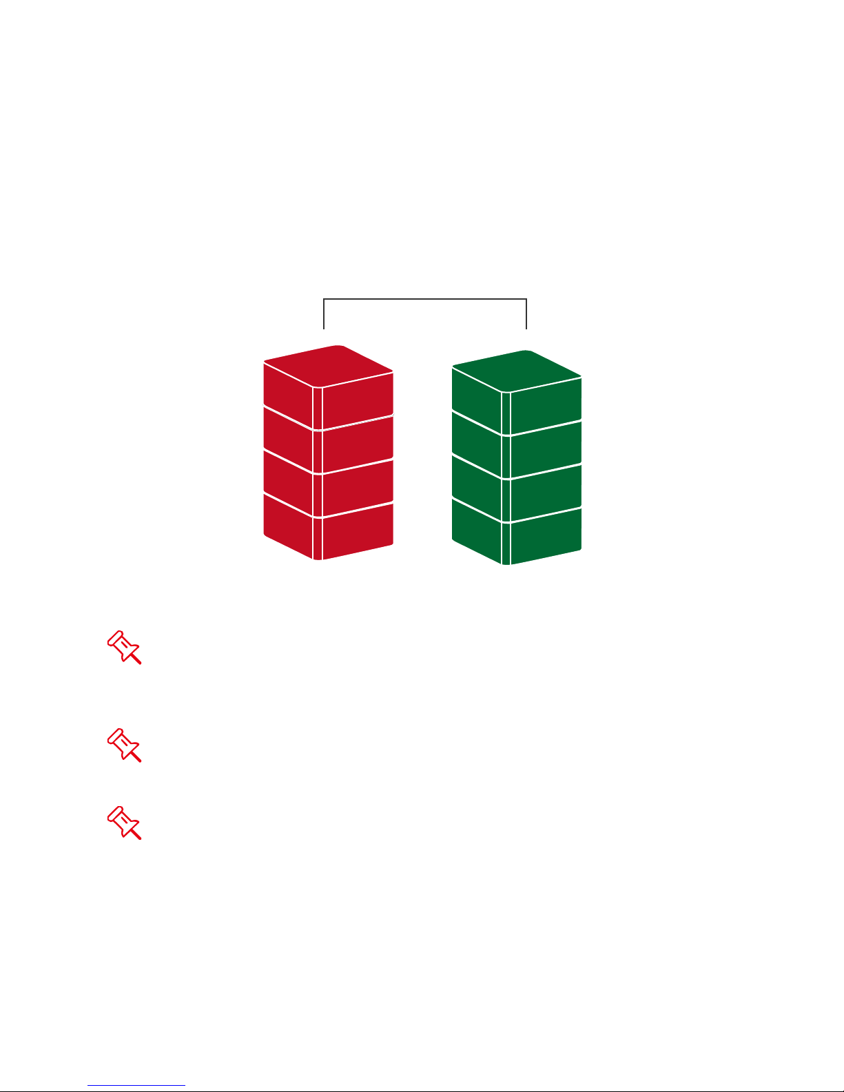
Just a Bunch of Disks (JBOD) refers to a group of hard drives. In JBOD, the
number of logical drives is equal to the number of physical drives. This mode
allows the RAID System to operate as a multi-disk storage enclosure, but
provides no data redundancy.
JBOD
A
B
C
D
Disk 1
Due to the chipset limitations, only cold hot swap is allowed in JBOD mode.
Therefore, the RAID System must be powered off when replacing any of the
HDDs in the System.
The eSATA interface cannot support the JBOD mode. It is only available
when connecting under the USB 2.0, FireWire 400, and FireWire 800 interfaces.
Disk 2
Ä
ß
Ç
µ
Due to the chipset design, when performing JBOD and only one HDD is
used, always insert it into the HDD 2 of the HDD slots.
Page 23

SETTING THE RAID MODE (MANUALLY)
Changing the RAID Mode deletes all data stored on the device. If you have
saved data in the drives, backup all data before changing the RAID Mode.
1. Power “off” the RAID System.
OF F
RAID
eSATA
DC IN
2. Use a small, flat-blade screwdriver to select the RAID Mode (RAID Switch).
RAID
eSATA
DC IN
Page 24

3. After setting the new RAID mode, power the RAID System “on”.
ON
RAID
eSATA
DC IN
It is highly recommended to always power off the RAID System before
setting or changing the RAID Mode Switch to ensure the changes are accepted
by the System.
RAID Switch
RAID 0 (Striping)
RAID 1 (Mirroring)
JBOD
Page 25

HDD SLOT NUMBER
2
1
HDD ALLOCATION
It is highly recommended
to help identify the HDD allocation. Although the HDD slots can help with
organization, when the hard disks are pull out without remembering their
arrangement order, the data may be lost if the HDD allocation is not the same as
the one originally set in the RAID System.
to use the numbering stickers provided in the package
11
Page 26
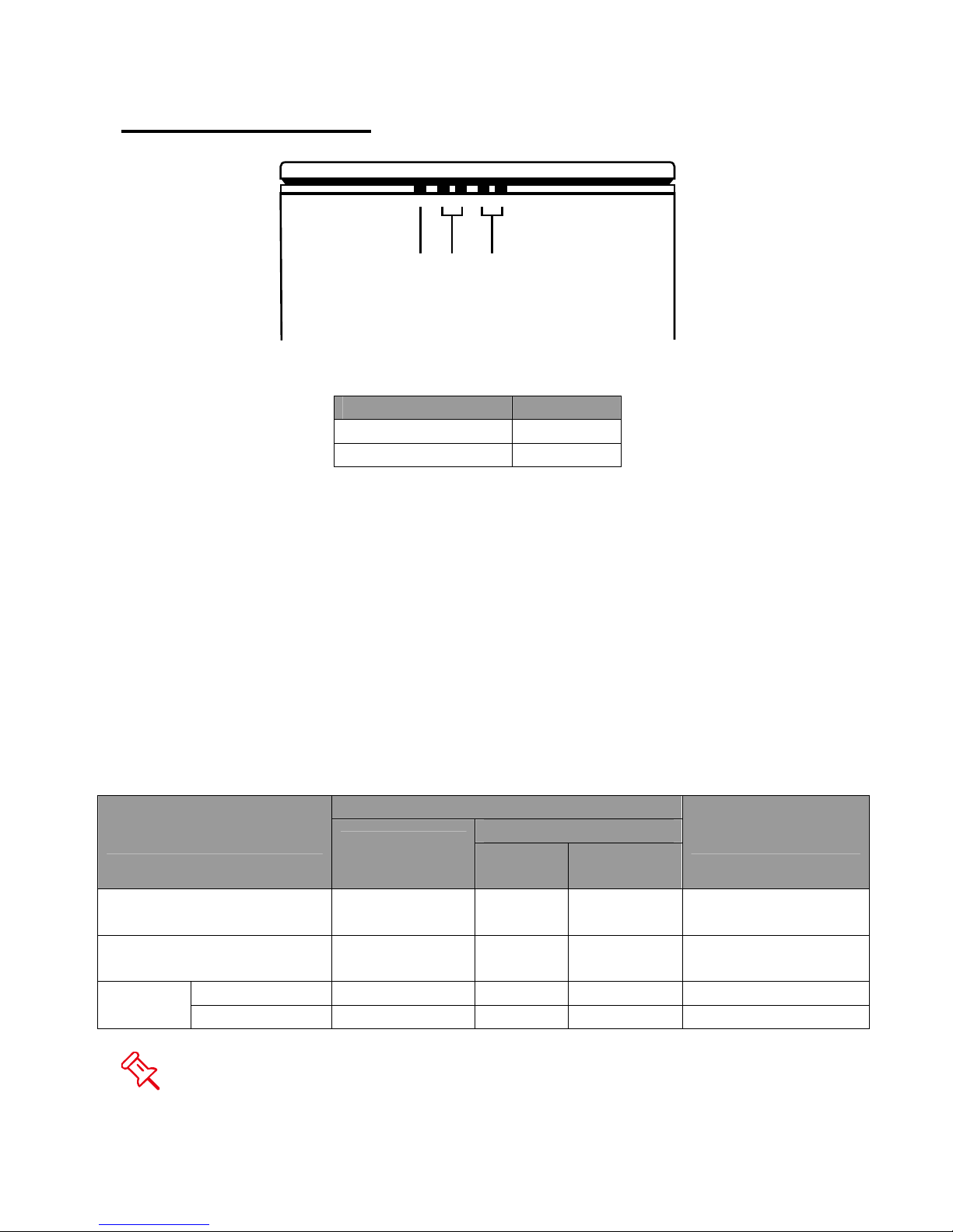
LED INDICATORS
Power
HDD 2
HDD 1
Power LED x 1
Indicators Color
Power on Green
Power off None
HDD LED x 4
There are 2 LEDs for each HDD slot. The left LED indicates “Connection” and
the right one indicates “Health/Access”.
The Connection LED is only one-color (white). When the HDD is connected, the
white LED will be on. The Connection LED also indicates HDD power status and
disk rebuild status. When the target HDD is being rebuilt, the white LED will blink.
The Health/Access LED is dual-color (red/blue). The red color is for Health
condition. The blue color is for Access condition. When the HDD is not healthy,
the red LED will be on. When the HDD is being accessed, the blue LED will flash.
When HDD is healthy and not being accessed, no LED color will be on.
HDD (1, 2)
Indicator
Disk error None Red None
Data access White None Flash Blue
Disk
Rebuild
Left
(Connection)
Source HDD White None Blue RAID 1
Target HDD Blink White None Blue RAID 1
Color 1
(Health)
Right
Color 2
(Access)
RAID mode
RAID 0, RAID 1,
JBOD
RAID 0, RAID 1,
JBOD
The difference between a flashing LED and a blinking LED is that flashing
refers to the read/write activity and blinking refers to slow but regular pulses.
Page 27

SAFE REMOVAL OF THE RAID SYSTEM
Safe removal of the Enclosure from the host controller is highly recommended,
especially when switching interfaces. In order to safely remove your Enclosure
from the host controller, you would need to eject the device on your host
controller system.
If using a Mac System, safe removal of the Enclosure from the host for all
interfaces is n ecessary.
If using a PC System, safe removal of the RAID System from the host
depends on the interface. Most current USB and FireWire host controllers
handle USB and FireWire devices as external devices; thus, it is highly
recommended that the Enclosure be safely removed from the host if you are
using either one of the interfaces. However, if you are using the eSATA
interface, depending on the eSATA controller, the host may handle external
eSATA HDD devices as internal HDD devices. If so, safe removal of the
Enclosure from the host is unnecessary.
Page 28

EXTERNAL BOOTUP
External Bootup may be required if the user has two different operating systems
set up in both the host computer and the RAID System.
PC
The External Bootup with different interface:
OS \ Interfaces USB 2.0 FireWire eSATA
Windows No No Yes
DOS Yes No Yes
Linux No No Yes
MAC
The External Bootup varies with different platform and interfaces:
eSATA
No Driver Built-
in
Platform \ Interfaces
Power PC CPU
(G4 or Later)
USB
2.0
No No Yes No
FireWire
Mac driver
Built-in
Intel-based
CPU
If the computer does not come with eSATA interface and an optional eSATA
card is added, choosing the card that comes with the built-in driver in the
operation system is highly recommended
CoreDuo Yes No Yes No
Core2Duo
Or Later
Yes Yes Yes No
.
Disk Volume Over 2TB
The 2+TB HDD support is determined by the chipset used in the device and the
operating system itself. The RAID System supports and recognizes 2+TB HDDs,
but the actual 2+TB support will vary depending on the different operating
systems used.
OS USB FireWire eSATA
Windows 2000, XP, or older No No No
Windows XP 64-bit, Windows 2003 32-
Windows
Linux Linux 32-bit/64-bit No No No
Mac
bit/64-bit (SP1 and SP2)
Windows Vista, Windows 2008 32bit/64-bit
Mac OS 9/10.1/10.2 No No No
Mac OS 10.3/10.4/10.5 Yes Yes Yes
Yes No Yes
Yes Yes Yes
Page 29
eSATA PCI EXPRESS CARD INSTALLATION
Complete the steps provided in this section to install the eSATA PCI Express
Card to use with the RAID System. The eSATA PCI Express Card provides a
host computer with two Windows and Mac compatible eSATA ports.
System Requirements
Windows 2000 with Service Pack 4 or later
Windows XP with Service Pack 2 or later
Windows 2003 with Service Pack 1 or later
Mac OS 10.4.x or later
An available PCI-Express slot
CD-ROM or DVD-ROM drive
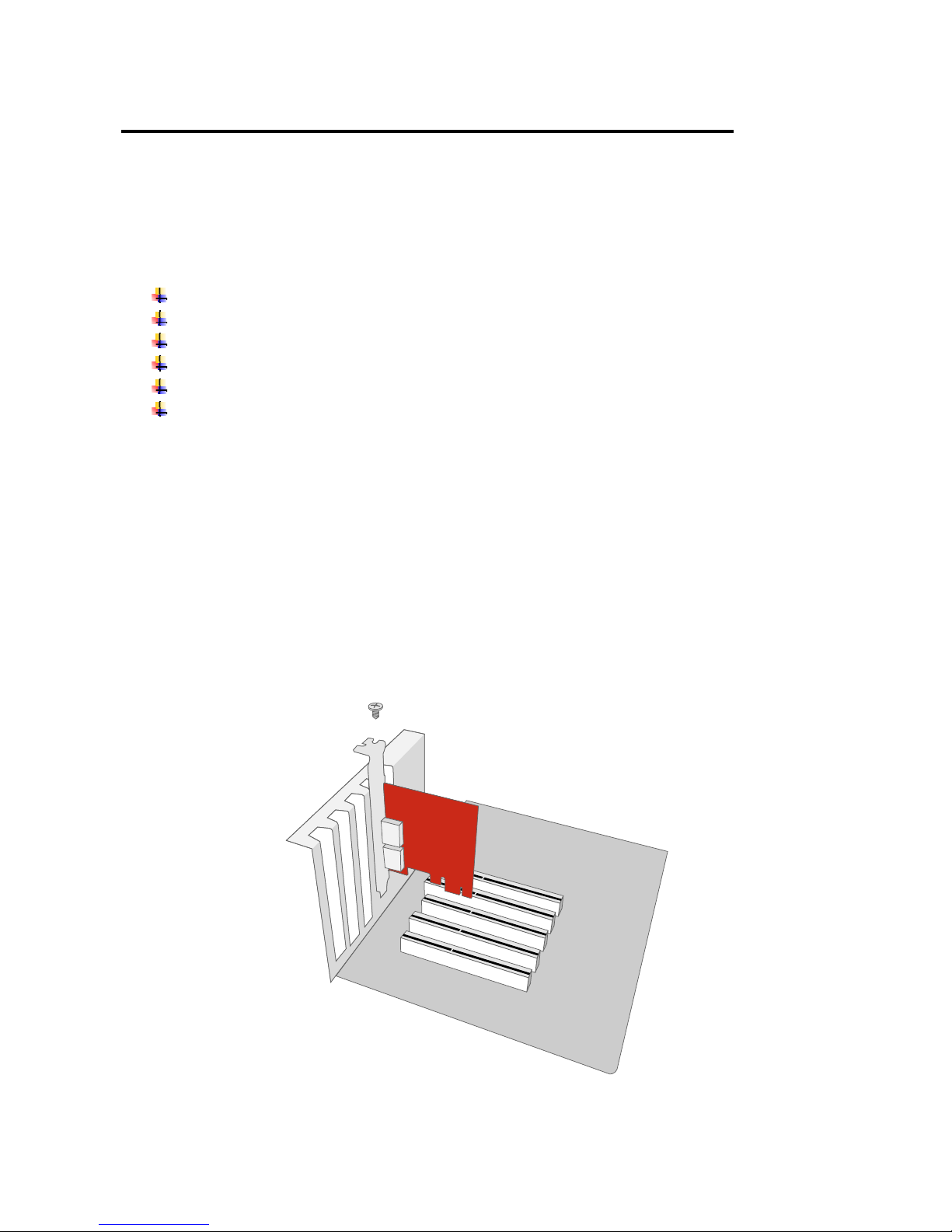
Hardware Installation
1. Power “off” and unplug your computer.
2. Remove the housing of your computer and locate an available PCI-Express
slot on your motherboard.
3. Insert the card in the available PCI-Express slot. Ensure that the card is
firmly seated in the slot.
4. Replace the housing of your computer.
System
Frame
Screw
PCI-Express
Card
Mounting
Bracket
Page 30

Driver Installation
Follow the provided prompts to complete the driver installation.
For the Windows system, the “Add New Hardware Wizard” will open
automatically. Insert the installation CD included in the package, navigate to and
open the installation file.
For Mac OS, insert the installation CD and locate the Mac driver installation file.
Follow the provided instructions to complete the driver installation.
Please refer to User’s Manual under eSATA Host Card section on our
website.
Verify Driver Installation
Mac OS:
If a driver installation failure error message appears after restarting the
computer, follow the recommendations provided in the error message.
Windows OS:
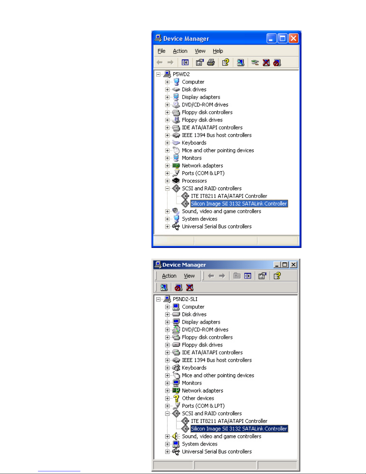
1. Right-click the My Computer icon on your desktop and choose Manage from
the pop-up menu.
2. Double-click Device Manager.
3. Double-click SCSI and RAID controllers.
4. Verify that the SiI 3132 SATALink Controller appears, as shown below.
Page 31
Windows 2003 and XP:
Windows 2000:
Page 32
Q&As
General
Q: When I have finished changing the RAID mode, how come the System cannot
accept the change and is still in the previous mode?
A: To make sure that the System accepts the RAID mode changes, you will need
to power off the System first. When you power it back on, the System will accept
the changes. It is highly recommended to always power off the RAID System
before setting or changing the RAID Mode Switch to ensure that the changes are
accepted by the System. Please be cautioned that changing the RAID mode can
delete all data in the System.
HDD Capacity
Q: All my HDDs are at least 1TB or above, will the RAID System be able to
support the gigantic storage capacity?
A: Yes, the RAID System will be able to support any HDDs over 1TB size
capacity. However, most older host systems cannot support over 2TB of total
capacity, only Mac OS 10.3 and newer, and PC Windows Vista or newer. In
addition, based on the host system you have, there may be limitations on the port
connections when the storage size is over 2TB. Please see the chart below.
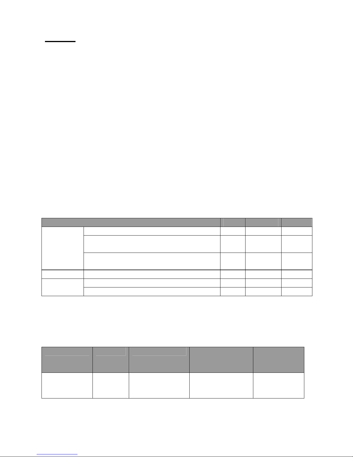
OS USB FireWire eSATA
Windows 2000, XP, or older No No No
Windows XP 64-bit, Windows 2003 32-
Windows
Linux Linux 32-bit/64-bit No No No
Mac
Q: I would like to format my hard drives with the FAT (a.k.a. File Allocation Table)
format, which can be read and written by both Mac and PC. Is there any
limitation on its capacity?
A: Yes, please check the table below for reference.
File System NTFS FAT32 FAT (Format by
Capacity
Limitation
bit/64-bit (SP1 and SP2)
Windows Vista, Windows 2008 32bit/64-bit
Mac OS 9/10.1/10.2 No No No
Mac OS 10.3/10.4/10.5 Yes Yes Yes
Win2000 /
WinXP)
Vista:
16384TB
XP: 2TB
Windows: 32GB
Mac: 2TB
4GB 2GB
Yes No Yes
Yes Yes Yes
FAT16
Page 33
Discrepancy in Reported & Actual Size Capacity
Q: If I have a 750GB HDD, why does the RAID System only recognizes the HDD
available space as to be less than 750GB?
A: Many customers are confused by their host systems when it reports a
discrepancy between reported capacity and actual capacity. Several factors can
come into play when your host system views and reports the capacity of a hard
drive. There are actually two different numbering systems used to express units
of storage capacity:
Binary, which says that a kilobyte is equal to 1024 bytes; and
Decimal, which says that a kilobyte is equal to 1000 bytes.
Most commonly used to display storage capacity is in Decimal. The surprising
fact is that even though it seems like you will have more bytes under Binary, the
Decimal calculation system actually presents a greater storage capacity. More
description on capacity issues can be found at the Seagate website under FAQs.
http://www.seagate.com/ww/v/index.jsp?locale=enUS&name=Storage_Capacity_Measurement_Standards__Seagate_Technology&vgnextoid=9493781e73d5d010VgnVCM100000dd04090
aRCRD
HDD Allocation
Q: I've pulled out all the disks inside the RAID System and now I want to put
them back, but I don't remember the HDD allocation. Will my data be safe if I put
the HDDs back into the RAID System if they're not in the correct allocation?
A: No, it would NOT be safe for your data if the HDDs were not placed back into
the RAID System in their original arrangement order. We would highly
recommend all users to use the number stickers in the package to help identify
which HDD belongs to which HDD slot. You may stick them onto the handles or
HDDs as identification.
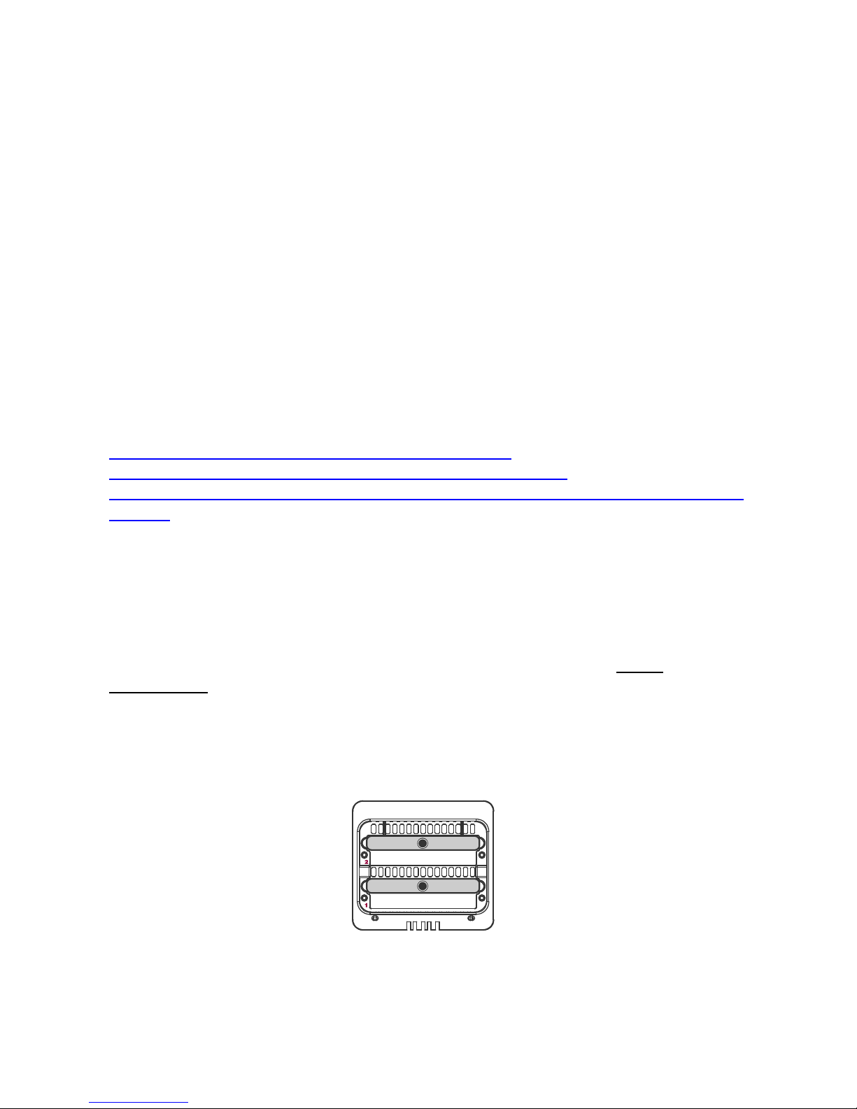
HDDAllocation
2
1
Page 34

RAID 0
Q: I am using one HDD in the capacity of 750GB and another HDD in the
capacity of 500GB under the RAID 0 mode. Why is the total capacity not 750GB
+ 500GB?
A: Using identical HDDs with the same capacity and RPM, and from the same
manufacturer are highly recommended
for BEST capacity utilization.
JBOD
Q: I cannot do the JBOD under the eSATA connection? Why?
A: Due to the chipset design, the JBOD mode cannot be performed under the
eSATA connection.
Q: I have inserted one HDD under the USB connection, but the system cannot
recognize it. Why?
A: Please insert the HDD into the HDD 2 of the HDD slots instead of HDD 1.
Page 35
APPENDIX: SPECIFICATIONS
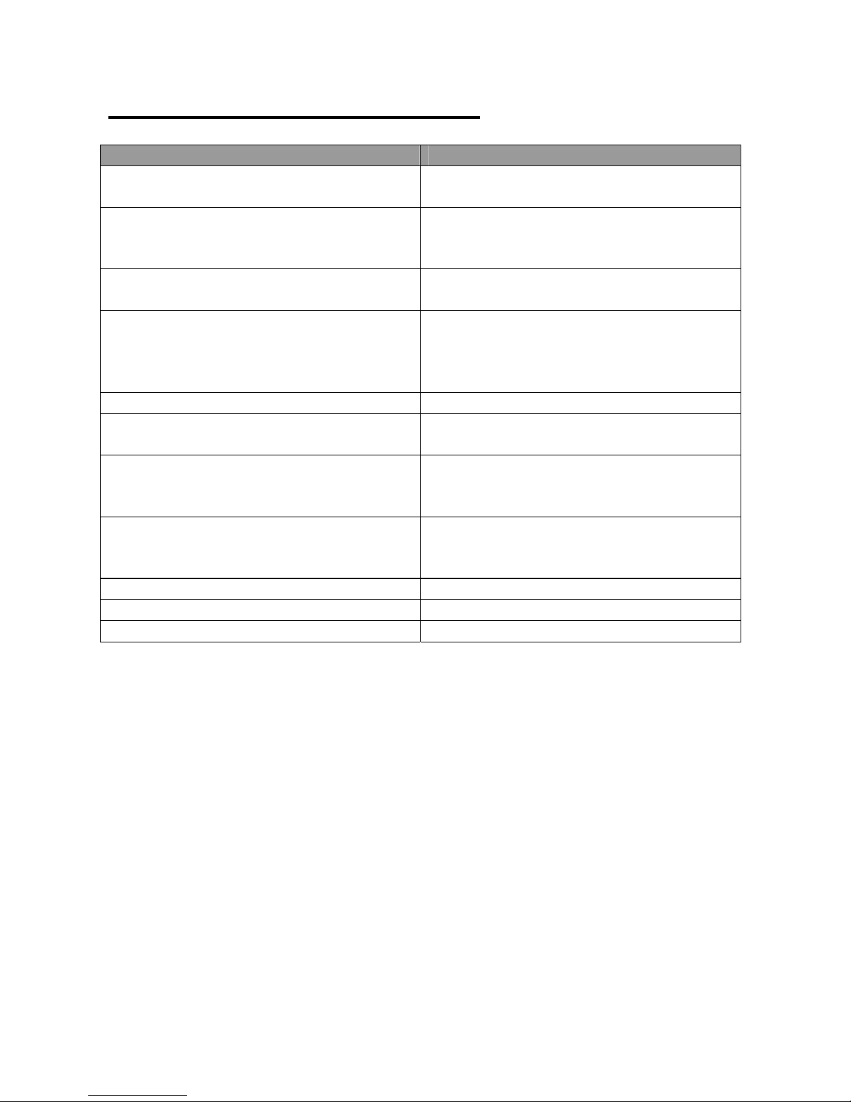
Model Name IB-RD3262-USE2
Connector
HDD Support
RAID Level
Data Transfer Speed
System Material Aluminum case with plastic parts
LED Indicators
Power Supply
FAN
Dimension 126 (L) x 138 (W) x 213 (H) mm
Weight (without HDD) 1.35 KGS
Certification CE, FCC
eSATA x 1, USB 2.0 x 1, 1394a x 1,
1394b x 1
3.5” SATA HDD*
*Identical HDD recommended – same
manufacturer, capacity and RPM
RAID 0 (Striping), RAID 1 (Mirroring),
JBOD
eSATA: up to 3Gbit/sec
USB 2.0: up to 480Mbit/sec
1394a: up to 400Mbit/sec
1394b: up to 800Mbit/sec
Power / Connection / Health / Access /
Rebuild
Input: AC 90-264V
Output: DC +12V/2A, +5V/2A
Peak current: 4A, 3.7A
Dimension: 80 x 80 x 10 mm x 1
Speed: 1900 R.P.M +-10%
Noise: 17.13 dB(A) max
Page 36

Dateiname: 10‐06‐10_IB‐RD3262_Manual_Draft_ENG_Bastian(2).doc
Verzeichnis: C:\DokumenteundEinstellungen\MarianKleefeld\Lokale
Einstellungen\TemporaryInternetFiles
Vorlage: C:\DokumenteundEinstellungen\Marian
Kleefeld\Anwendungsdaten\Microsoft\Templates\Normal.dotm
Titel:
Thema:
Autor: Mac
Stichwörter:
Kommentar:
Erstelldatum: 16.06.200916:46:00
ÄnderungNummer: 11
LetztesSpeicherdatum: 21.06.201015:13:00
Zuletztgespeichertvon: ‐
LetztesDruckdatum:21.06.201015:44:00
NachletztemvollständigenDruck
AnzahlSeiten:35
AnzahlWörter: 4.029(ca.)
AnzahlZeichen: 25.386(ca.)
 Loading...