

Page 1
Address 1 - Card / Tag Format
The card/tag transponder format defines how the ICT
Proximity Reader will decode cards and tags that are
presented during standalone and normal operation.
Setting Function
1 Read all card tag types.
2 ICT Prox Format
3 Postech Format
4 HID Format
5 ICT and HID Format
6 ICT and Postech Format
7 Postech and HID Format
Address 2 - Data Interface
The data interface format defines how the data is sent
using the DO and D1 data interface.
Setting Function
1 26 Bit Wiegand Format
2 34 Bit Wiegand Format
3 37 Bit Wiegand Format
4 37 Bit Wiegand Alternate Format
5 Card Defined Wiegand Format
Address 3 - Led Control
The LED Control Configuration settings allow the LED
lines to operate in either multiple LED or single LED
control.
Setting Function
1 Dual LED Input
Red LED control line controls Red
LED. Green LED control line
controls Green LED.
2 Red LED Always On
Red LED control line will turn Red LED
off and Green LED on.
3 Green LED Always On
Red LED control line will turn Green
LED off and Red LED on.
Address 4 - Intelligent Tamper
Enabling the intelligent reader tamper mode will force
the ICT Proximity Reader to check in to the device it is
connected to every 30 seconds.
Setting Function
1 Disabled
2 Enabled
Address 5 - External Button
External button input allows the second LED input to be
used as a multiple function input for Area Arming, Request
to Exit and Request to Enter buttons.
Setting Function
1 Disabled
2 Enabled
SPECIFICATION
Power Supply
Voltage 12VDC (9.5 - 14.0VDC)
Current 120mA (Peak, Reading)
Read Range
Card Up to 10cm (4")
Tag Up to 6cm (2.5")
Stand Alone Operation
Users 100
Access Level 3 Master, Super, User
Interface
Wiegand Multiple Format 26, 34, 37 Bit
Data 0 and Data 1
Distance 150 Meters (500 feet)
Frequency
Field 125KHz Pulse Width Modulated
Cable Type
Multi Conductor 22Awg Alpha 5196, 5198
18Awg Alpha 5386, 5388
18Awg Beldon 9553
Temperature
Operating -35˚- +65˚ Celsius
-31˚ - 149˚ Fahrenheit
*Specifications are subject to change without notice, ple ase
visit www.integratedcontroltechnology.com for the updated
information.
Unit C, 6 Ascension Place, Mairangi Bay, P.O. Box 302-340
North Harbour, Auckland, New Zealand.
Phone: +64 (9) 476 7124 y Fax: +64 (9) 476 7128
www.integratedcontroltechnology.com
Nano-Prox
VARIO-PROX
Quick Start Guide
INTRODUCTION
Thank you for choosing a Proximity Reader from
Integrated Control Technology. The Proximity Reader is
an advanced technology radio frequency identification
device (RFID) specifically designed to enhance the
functionality of security, building automatio n and access
control by providing multiple format compatibility, high
speed data transmission, built in stand alone operation
and sabotage protection.
The Reader is designed to operate as a Normal Wiegand
Proximity Reader or as a complete Standalone Single
Door Controller.
For a full installation manual or more information on the
Proximity Reader and other Integrated Control
Technology products please login to
www.integratedcontroltechnology.com
Page 2
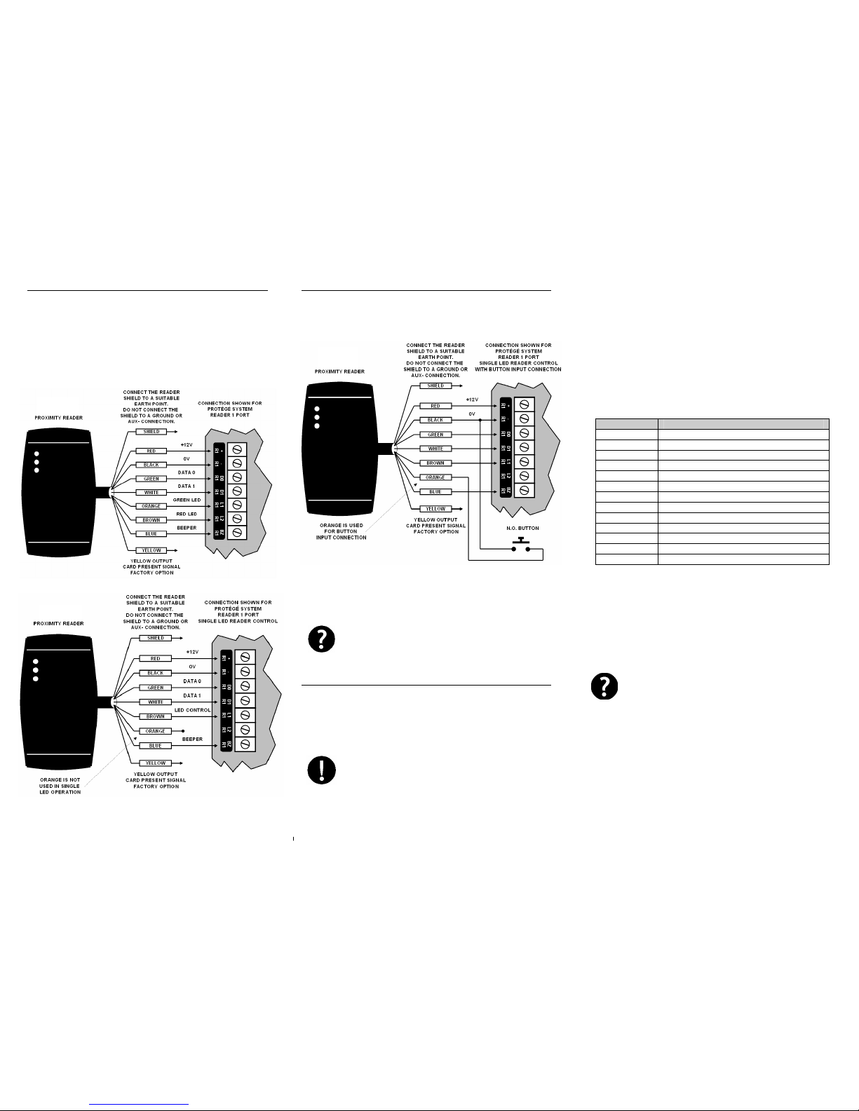
WIEGAND CONNECTION
When using the standard Wiegand Interface to the
access controller or reader expander two wiring methods
can be used. Dual LED operation allows the signalling o f
both LED's independently using the LED control lines and
is ideal to show the status of alarm or o ther integrated
signals.
Figure 1 – Dual LED Connection
Single LED allows a single LED line to control both LED
colours.
Figure 2 – Single LED Connection
AUX BUTTON INPUT
Button input wiring configuration is shown in Figure 3. For
programming options refer to the Protégé System Manual
or the access controller manual for the system that the
Proximity Reader is connected.
Figure 3 - Button Input Wiring
Connect a normally open button or switch as shown in
Figure 3 and complete the programming within the Protégé
Integrated System for the functionality required.
External Button Input Mode and single LED
operation must be enabled when using this
wiring configuration. PROGRAMMING
INSTALLER PROGRAMMING
By default the ICT Proximity Reader is facto ry co nfigur ed t o
send data in 26 Bit Wiegand Format, it will read all card
formats and operate in the dual LED line mode. This
configuration can be changed to suit system operating
requirements.
The programming card can only be presented
within the first 2 minutes from when the card
reader powers up.
Entering Program Mode
To program the Card Reader badge the programming
card once, the Card Reader will beep to indicate the card
has been read and then beep twice and illuminate the
RED LED to indicate programming mode has been
entered.
Address Selection
To select an address to program the programming card is
presented to the card reader the number of times
matching the address number.
Address Programming Option
1 Card Reading Format
2 Data Output Format
3 LED Configuration
4 Intelligent Tamper Mode
5 Auxiliary Button Input Mode
6 Operating Mode
7 Add Standalone Master Card
8 RS485 Address
9 Door Pre-Alarm Time
10 Door Left Open Time
11 Version Information
12 Default
15 Client Code Configuration
For example to program address three (LED
Configuration) the programming card will be presented to
the card reader three times.
The card reader will then respond by beeping twice and
flashing the RED LED to indicate data entry mode has
been entered and that the user should present the card
the required number of times to set the desired option.
Entering an address value that does not
exist will result in the reader timing out and
a long Beep tone being generated.
Data Programming
To program a data value in the selected address location
the same method as the address programming is used.
Present the Programming Card to the reader the number
of times matching the data value or option for the
selected address. The card reader will then respond by
beeping twice indicating the data was programmed
correctly and return to the address selection mode. An
invalid entry will result in a long tone being generated.
The data can be entered again or allow the Nano Prox to
timeout to select another address.
 Loading...