

Page 1

Intelligent digital conference
system
User Manual
TS-0698
Please Read This Manual Before Operation
Page 2

2
NOTE:
This manual only as an instructions for user, not for service purposes. From the date of
issue, if the function or technical parameters change later, another supply mentary instruction
will be added, the details can be inquired to the manufacturers.
This manual is a product manufacturer Copyright, unauthorized and any entity or
individual shall not take part or all the contents as commercial purposes.
This manual used for intelligent digital conference system.
Page 3

3
!
SAFETY OPERATIONAL GUIDANCE
In order to make sure the correct operation and safety using, please comply with the
following conditions when installation, operating and maintenance.
(3) Make sure the connection of the ground wire is well enough when installation.
Do not use two-core plug. And make sure the input voltage of power supply is as same as
the one marked on the main controller.
5) Do not open the cover of the unit without permission especially the high-voltage
components marked with AC 220V, or there is risk of shock.
3) Do not put the unit in extremely cold or hot place.
4) The unit will be heating when working. Please keep environment ventilation to avoid
overheating.
1. Please power off the unit in wet weather or not in use.
2. Please disconnect the AC power wiring from the AC power supply before the below
operations:
A. Remove or re-assembly any parts of the unit.
B. Disconnect or re-connect any plug of the unit or other connection
A. Non professionals without permission, please do not attempt to open the enclosure,
do not repair, in order to avoid the accident or exacerbation of equipment damage
degree.
8) Don't take any corrosive chemical powders or liquids spilled in the equipment or in the
vicinity of.
Page 4

4
1. Overview
About ITC digital conference system
Intelligent digital conference system is another high-tech professional product series after
the control system and multimedia audio and video matrix product including discussion,
which including discussion unit, simultaneous interpretation, the infrared voice distribution,
long-distance telephone meeting, voting , and camera tracking system.
In order with the concept of the all along proposed overall system integration solution,
tight compatibility between the two different systems DCS(digital conference system) and
MCS(multimedia central control system) can be achieved. In this way a comprehensive
-product digital conference system solution can be composed.
This user manual is used for digital conference system controller, discussion unit, camera
traking system and telephone Conference system.
Page 5

5
TS-0698 Mainframe for camera shooting and tracking
Product Overview
TS-0698 is a high definition mainframe for camera shooting and tracking, working with
TS-0604M and TH-0802H conference system in order to achieve automatic camera
shooting and tracking. A HDMI 5x1 matrix is built in, which has the function of image
-freezing and can support 5 vidicons at most.
Features
1. The camera shooting and tracking function of TS and TH conference system’s
mainframe is supported.
2. Tracking location can be pre-installed through PC software. 5 channels HDMI
signal input and 1 channel display output are supported.
3. VISCA, Pedicel-D, Samsung protocols are supported.
4. 9600bps/2400bps/4800bps/19200bps Baud rate are supported.
5. RS232 and RS485 communication modes are supported.
6. Image-freezing function can be custom-made according to customer’s need.
Introduction of the principle of camera shooting and tracking
Suppose that there are 10 units in the conference room, in FREE mode, and 2 minutes
have past after starting up. When the first microphone is opened, the camera will turn
around. When the second microphone is opened, the camera will turn to the location of
the second microphone. Successively 10 microphones are all opened. At last the camera
will face towards the location of the 10thmicrophone. When the 10thmicrophone is closed,
the camera will face towards the 9thmicrophone. When the 9thmicrophone is closed, the
camera will face towards the 8thmicrophone. The rest can be done in the same manner.
When all the microphones are closed, the camera will come back to the full view location.
Page 6

6
Illustration for the introduction of function
Front panel
1. HDMI signal input indicator light
2. Power switch
3. Power light
Real panel
4. Power input, support AC100-240V input
5. Ground terminal
6. HDMI INPUTS —Connected with five channel HDMI signal input. If video channel to
electricity after plug wire first, then the default minimum video output channel number,
such as: at the same time input 2, 3, 4 video source output 2 way to OUT. Should after
electricity access video signal, the output is the default of the thrust line of the video signal
source all the way.
7. HDMI OUT —Output HDMI high definition video signal
8. CODE —Camera type, communication protocol and Baud rate set switch(Not
support other vendor’s protocol yet )
9. CAMERA NET—Used for high-speed camera RS-232
10. CAMERA NET—Used for high-speed camera RS485
11. DATA—connected with conference system controller TH-0802M
12. CONFERENCE —connected with conference controller (TS series conference
system controller)
13. CONTROL —connected with control system(PC)
Page 7

7
Specification
Model TS-0698
Power supply AC100-240V 50/60Hz
Max power consumption 7W
Video signal bandwidth 1.65GHz
Video input signal electronic level 1.2 volts p-p
DCC input signal electronic level 5 volts p-p (TTL)
Single channel connection signal range 1080p/1920x1200
HDMI Connector Type A needle 19 female head
Power 15W
Weight About 3Kg
Dimension 484(L)× 210(L)× 44(H)mm
Color Black
PC software usage introduction
1. five video Channel
First of all, set up conference platform,
1) Video channel IN1 - IN5 input respectively connected with the camera address the 1-5
video output.
2) Open the PC software, setup the port, through the switch of software, the screen can
show different frames of different channel.
3) Open the PC software, setup the port, through the switching of PC software to check
each channel frame quality and speed. And it also have the save function when the power
cutout.
2. Obtaining the dates of DIP switch (The factory default setting is at OFF position )
1) Dialing the DIP switch on the rear of the unit after re-power on(only effective after
re-power on), click “Obtain” key on the PC software to get the DIP switch settings of
Page 8

8
protocol, baud rate and camera type from the camera tracking controller. Please check if
3. Camera address setting
the settings of the protocol, baud rate and camera type are as same as the real
connection settings.
Dial the 1stbit to select VISCA protocol.
Dial the 2ndbit to select SAMSUNG protocol.
Neither the 1stbit nor the 2ndbit is dialed, which means to select Pelcd_D protocol.
Dial the 3rdbit to select the baud rate of the camera at 2400.
Dial the 4thbit to select the baud rate of the camera at 4800.
Dial both the 3rdand 4thbits to select the baud rate at 19200.
Neither the 3rdnor the 4thbit is dialed, which means to select the baud rate at 9600.
For ceiling camera installation, the 5thbit shoule be dialed; for wall mounted camera
installation, the 5thbit should not be dialed.
Input the corresponding camera address here to control the
corresponding cameras through following control keys. Notice: the camera address, vedio
channel and camera address code must be the same to make sure the correct controlling.
Page 9
9
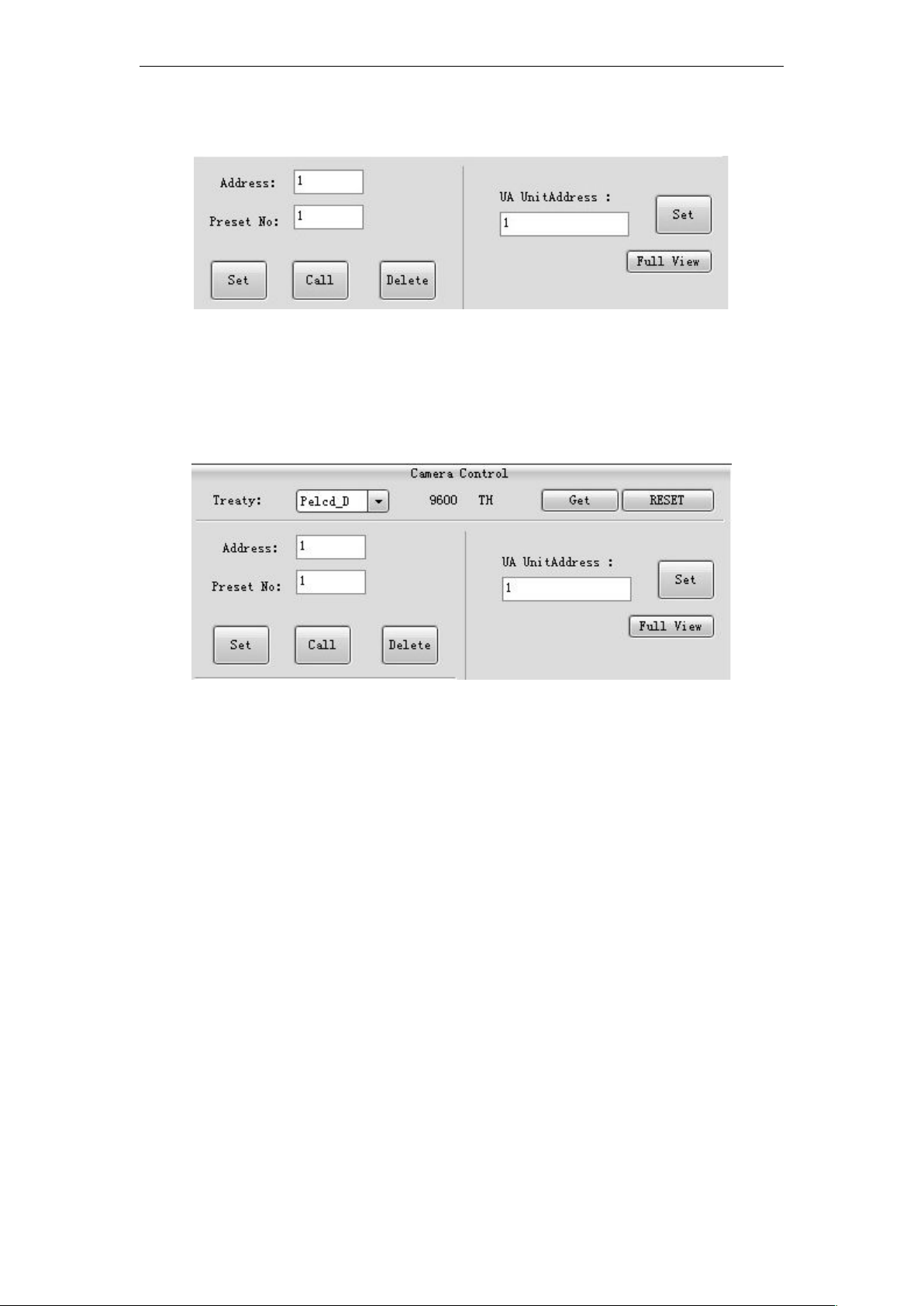
4. Pre-setting, delect and setting of the ceiling camera
Selecting the right camera protocol (setting in the unit), input the camera address and
5. Setting the pre-setting of the delegates
pre-setting position to begin the operation of controlling.
1) Selecting the right protocol, camera address, pre-setting position and delegate address,
adjusting the camera position through the “UP-DOWN-RIGHT-LEFT” keys to make sure it
points to the right delegate and then click “SAVE” to finish the setting progress. Settiing all
the pre-setting positions of the delegates in sequence to make sure the camera poins
automatically when any delegate turns on.
2) After setting all the delegates, please set the pre-setting position of the textbox as the
panoramic position. Click “setting panoramic position” to set the whole panoramic position
of the meeting place. (When all the mic delegates are turned off, the camera will turn back
automatically.)
5.1 Protocol test of controlling camera
Selecting either VISCA protocol or RS232/485 or Pelcd protocols to control the rotation of
the camera and the pre-setting.
Page 10

10
5.2 Controlling the different address cameras
Changing the phisical address of the cameras and controlling the rotation from the PC
software to realize mutiple cameras on-line using.
5.3 System on-line testing
Connecting two conference controllers, 9 units of TS series delegates, 9 units of TH series
delegates and the PC, then turn on the PC software. Setting the ID number on the
delegates and the pre-setting of each delegate. Then begin the microphone testing.
Checking if the camera rotation is correct or not when turning on several delegates or
turning off several delegates. There are several standards to judge if the rotation is correct
or not.
1) TS series and TH series conference systems should be tested interdependent, which
could not be tested as the same system.
2) For example, when turning on the 1st, 2nd, 3rd, 4th, 5thdelegate continuously, the camera
will point to the 5thdelegate. When the 5thdelegate is turned off, the camera will point to
the 4thdelegate; Switching off the delegates in turns, the camera will point to the
panoramic position. (The panoramic position should be setted by the PC software;
adjusting the camera position and then click it)
3) For example, when turning on the 1st, 2nd, 3rd, 4th, 5thdelegate continuously, the camera
will point to the 5thdelegate. Then switching off the 2nd, 3rd, 4thdelegates, the camera
position will not be changed. Then turn off the 5thdelegate, at this time the camera will turn
to the 1stdelegate.
4) For example, when turning on the 1st, 2nd, 3rd, 4th, 5thdelegate continuously, the camera
will point to the 5thdelegate. Then press the priority key of the 6thdelegate, all the
delegates will turn off the mic and the camera will turn to the 6thdelegate. Both TS and TH
delegates are in the same testing.
Page 11

11
Testing information table of TS-0698 (√ means the testing function is valid; - - means
TS series
tracking
TS series
tracking
control
Serial port
control
Channel
switching
VISCA protocol √ √
--
√ √
SAMSUNG
protocol
-- -- -- -- --
Pelcd_D
protocol
√ √ √ -- √
the testing fuction is invalid. )
 Loading...