

ICT PRX-VARIO Installation Manual

PRX-VARIO
Vario Proximity Card Reader
Installation Manual

The specifications and descriptions of products and services contained in this document were correct at the
time of printing. Integrated Control Technology Limited reserves the right to change specifications or withdraw
products without notice. No part of this document may be reproduced, photocopied, or transmitted in any form
or by any means (electronic or mechanical), for any purpose, without the express written permission of
Integrated Control Technology Limited. Designed and manufactured by Integrated Control Technology Limited.
Protege® and the Protege® Logo are registered trademarks of Integrated Control Technology Limited. All other
brand or product names are trademarks or registered trademarks of their respective holders.
Copyright © Integrated Control Technology Limited 2003-2012. All rights reserved.
Publication Date: November 2012
2 PRX-VARIO Vario Proximity Card Reader Installation Manual | November 2012

Contents
1 Welcome _________________________________________________________________ 4
1.1 Document Conventions ................................................................................................. 4
2 Mounting _________________________________________________________________ 5
2.1 Mounting Instructions .................................................................................................... 5
3 Wiegand Connection _______________________________________________________ 6
4 AUX Button Input __________________________________________________________ 7
5 Installer Programming ______________________________________________________ 8
5.1 Entering Programming Mode ........................................................................................ 8
5.2 Address Selection ......................................................................................................... 8
5.3 Data Programming ........................................................................................................ 9
5.4 Address 1 - Card/Tag Format ....................................................................................... 9
5.5 Address 2 - Data Inferface ............................................................................................ 9
5.6 Address 3 - LED Control ............................................................................................. 10
5.7 Address 4 - Intelligent Tamper .................................................................................... 10
5.8 Address 5 - External Button ........................................................................................ 10
5.9 Address 6 - Operation Mode ....................................................................................... 11
5.10 Address 7 - Master User ............................................................................................. 11
5.11 Address 8 - Device Address ........................................................................................ 11
5.12 Address 9 - Door Pre Alarm ........................................................................................ 12
5.13 Address 10 - Door Left Open ...................................................................................... 12
5.14 Address 12 - Default.................................................................................................... 12
5.15 Address 15 - Set Up Client Code ................................................................................ 13
6 User Programming _______________________________________________________ 14
6.1 Entering User Program Mode ...................................................................................... 14
6.2 Address Selection ....................................................................................................... 14
6.3 Address 1 - Add User .................................................................................................. 14
6.4 Address 2 - Add Super User ....................................................................................... 15
6.5 Address 3 - Add Master User ...................................................................................... 15
6.6 Address 4 - Super User Unlock ................................................................................... 15
6.7 Address 9 - Delete Users ............................................................................................ 15
7 Mechanical Diagram ______________________________________________________ 16
8 Technical Diagram ________________________________________________________ 17
9 Technical Specifications ___________________________________________________ 18
10 Ordering Information ______________________________________________________ 19
11 Warranty ________________________________________________________________ 20
PRX-VARIO Vario Proximity Card Reader Installation Manual | November 2012 3

1 Welcome
Thank you for choosing the Vario Proximity Card Reader from Integrated Control Technology. The Vario
Proximity Card Reader is an advanced technology radio frequency identification device (RFID) specifically
designed to enhance the functionality of security, building automation and access control by providing multiple
format compatibility, high speed data transmission, built in standalone operation and sabotage protection.
The Vario Proximity Card Reader is designed to operate as a Normal Wiegand Proximity Reader or as a
complete Standalone Single Door Controller. The Vario Proximity Card Reader can be programmed to perform
and operate using different card and data output formats.
Before installing the Vario Proximity Card Reader, we highly recommend you read this manual carefully and
ensure that the data formats you program will operate with the configured access control or security product.
The current features of the Vario Proximity Card Reader include:
y Bi Color LED (Red and green) with Independent or Single LED Control
y Programmable Wiegand Data Formats from 26 to 128 Bit with Card Configured Output
y Keep Alive Transmission every 30 seconds for Intelligent Tamper Management
y Fully encapsulated design for outdoor and indoor operation
y Read range up to 120mm (4.00”) with Clamshell type cards
When receiving the Vario Reader you should find the kit contains the items listed below. Please note that if you
do not have the correct contents, you should contact your distributor immediately.
y Vario Proximity Card Reader
y Vario Proximity Card Reader Quick Start Guide
y Mounting template sticker
For more information on the Vario Proximity Card Reader and other Integrated Control Technology products
please visit the ICT website (http://www.incontrol.co.nz).
1.1 Document Conventions
Indicates a warning or cautionary message
i
[TEXT]
Indicates an important note or advisory information
Indicates a hint or suggestion
Bold text enclosed in brackets is used to show a section number or address of a programmable
option or information on programming shortcut sequences
4 PRX-VARIO Vario Proximity Card Reader Installation Manual | November 2012

2 Mounting
The Vario Proximity Card Reader is intended to provide the reading component of access control, time and
attendance and alarm systems. It is intended to be mounted on a wall with adequate air flow around and
through it.
2.1 Mounting Instructions
1. Select where to mount the Vario Reader. Ensure the Vario Reader is mounted a minimum of 1.1m (3.5ft)
away from other wiring. E.g. ACM power, computer data wiring, telephone wiring and wiring to electric lock
devices. Use the template sticker provided in the kit as a guide to correctly position the Vario Reader.
2. Hold the rear case half against the wall and mark the mounting holes and cable entry area. The cable entry
area should align with a hole cut through the plaster wall-board. Cables are intended to be run inside the
wall. Use appropriate screws (not supplied) to affix the case to the wall.
3. Run the wiring. Refer to later sections of this manual for the electrical connections. Leave about 20cm (8") of
wire protruding through the centre of the mounted half of the case.
4. Connect the wiring to the Vario Reader electronics, then use the top case to press gently on the bottom
mounted case until you hear the clip snap into place.
PRX-VARIO Vario Proximity Card Reader Installation Manual | November 2012 5

3 Wiegand Connection
When using the standard Wiegand Interface to the access controller or reader expander two wiring methods
can be used. Dual LED operation allows the signalling of both LEDs independently using the LED control lines
and is ideal to show the status of alarm or other integrated signals. Single LED allows a single LED line to control
both LED colors.
SHIELD
RED
BLACK
GREEN
WHITE
ORANGE
BROWN
BLUE
+12V
0V
DATA 0
DATA 1
GREEN LED
RED LED
BEEPER
R1 R1 R1 R1 R1 R1 R1
+AUX- DO L2D1 L1 BZ
YELLOW
Dual LED Connection
SHIELD
RED
BLACK
GREEN
WHITE
ORANGE
BROWN
BLUE
YELLOW
Single LED Connection
+12V
0V
DATA 0
DATA 1
GREEN LED
RED LED
BEEPER
R1 R1 R1 R1 R1 R1 R1
+AUX- DO L2D1 L1 BZ
Using the recommended cables as listed under the Technical Specifications, splice these cables together with
the pigtail of the reader and seal the splice. Route the cable from the reader to the host controller. Connect the
cables as shown in the diagrams above for either Dual LED Operation or Single LED Operation.
Connect the reader shield to a suitable earth point. DO NOT connect the shield to a ground or AUX
i
connection. DO NOT connect the shield wires together at the reader cable splice. With the shield wire
already terminated at the reader terminate the shield at the controller.
6 PRX-VARIO Vario Proximity Card Reader Installation Manual | November 2012
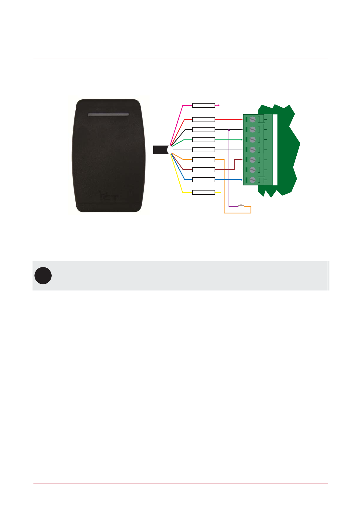
4 AUX Button Input
Button input wiring configuration is shown below. This hardware option must be enabled using the Vario Reader
Installer Address 5. For programming options refer to the Protege System Manual or the access controller
manual for the system that the Reader is connected to.
SHIELD
RED
BLACK
GREEN
WHITE
ORANGE
BROWN
BLUE
YELLOW
+12V
0V
R1 R1 R1 R1 R1 R1 R1
+AUX- DO L2D1 L1 BZ
RS-485 Interface
Connect a normally open button or switch as shown in the diagram above and complete the programming
within the Protege Integrated System for the functionality required.
Connect the reader shield to a suitable earth point. DO NOT connect the shield to a ground or AUX
i
connection. External Button Input Mode and single LED operation must be enabled when using this
wiring configuration.
PRX-VARIO Vario Proximity Card Reader Installation Manual | November 2012 7
 Loading...