

Page 1
PRT-KLCS
Protege Touch Sense LCD Keypad
Quick Start Guide
1. Introduction
Thank you for purchasing the Protege Touch Sense LCD Keypad by
Integrated Control Technology. The Touch Sense Keypad provides
a sleek, user friendly human interface to the Protege Integrated
System, an advanced technology security product providing
seamless and powerful integration of access, security and building
automation.
When receiving the Touch Sense Keypad you should find the kit
contains the items listed below. Please note that if you do not have
the correct contents, you should contact your distributor
immediately.
Protege Touch Sense LCD Keypad
Protege Touch Sense LCD Keypad Quick Start Guide
4 1K Ohm Resistors
2 2K4 Ohm Resistors
For more information on the Touch Sense LCD Keypad and other
Integrated Control Technology products please visit the ICT website
(http://www.incontrol.co.nz).
2. Configuration
Before the keypad will communicate with the Protege System it
must be assigned an address.
To program an address using the system configuration menu, apply
power to the keypad and when the screen displays the keypad
version information, press the
key then press . A
configuration menu is displayed. Scroll the available options by
pressing the up and down keys and
to select the menu item.
The configuration menu can only be accessed when the
keypad powers up. It cannot be accessed when the keypad
is operational.
Keypad Address
The address selection sets the address of the keypad. This address
must be a unique address in the Protege System that is below an
address of 250.
Enterdevice
address:256
Use the numerical keys 0 to 9 to program
the address and press
to save the
setting. To exit without making changes
press the
key.
Display Contrast Setting
The display contrast setting adjusts the LCD display contrast
settings.
Contrast
[*******]
Use the left and right keys to adjust the
contrast and press
to save the setting.
To exit without making changes press the
key.
Default Configuration
The default setting resets the keypad to the factory default settings.
Press[ENTER]to
defaultkeypad.
Press to default the keypad. To exit
without defaulting the keypad press the
key.
Keypad Version Information
The version menu option displays the version and build information
about the keypad. The version information is displayed on two lines
and can be scrolled. Press the
key to exit.
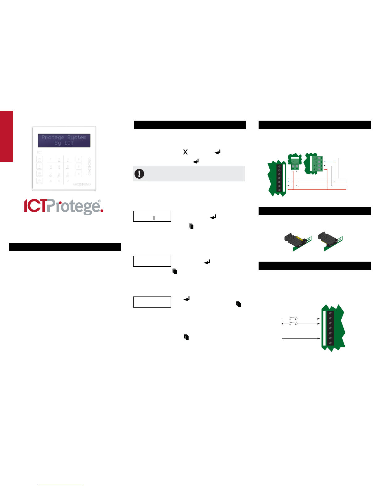
3. Communication
The Protege System incorporates encrypted RS-485
communications technology for its module network. Each system
controller supports up to 250 keypads.
NAN+ N- NB
Next modules
on network
System Controller Module Network
Communicaon Terminals.
Power Supply for Network
Devices Powering modules
on the system controller
Keypad Terminal
Connecon
+AUX-
-+NANB P1Z1 Z2
Standard Communications Connection
4. End of Line Termination (EOL)
The EOL (End of Line) jumper should be placed in the ON position
when the keypad is inserted as the FIRST or LAST module on the
RS-485 network.
EOL OFF
EOL ON
EOL Jumpers
5. Inputs
The keypad is capable of connecting to 4 zone inputs, where each
zone input can then be programmed to perform the required
function in the Protege System.
The following diagrams show examples of the zone wiring
configuration settings that can be programmed under the Keypad
General Options settings. For more information please refer to the
Protege System Controller Reference Manual.
Common
Zone 1 (1+2)
Zone 2 (3+4)
Zone 2
N.C Zone Contact
Zone 1
N.C Zone Contact
Z2P1 Z1 NB +NA -
Zone Input (No Resistors)
Page 2
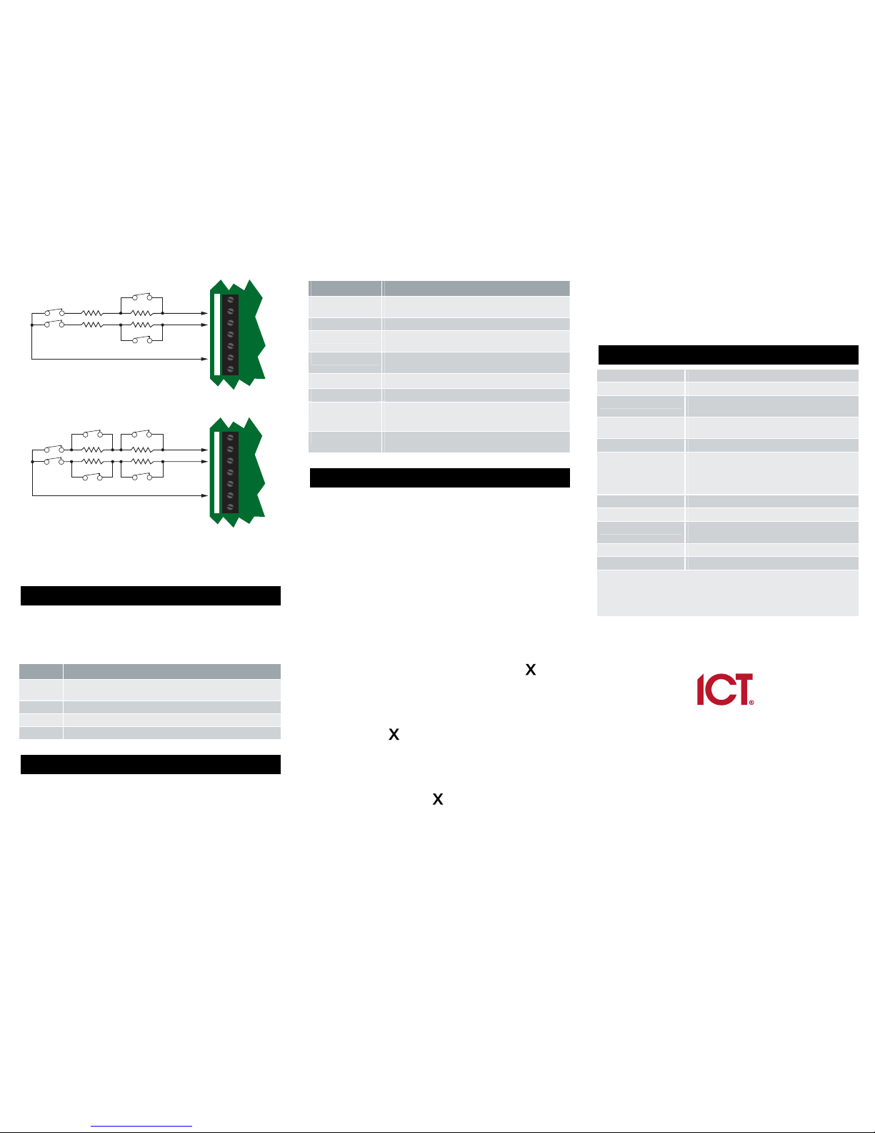
Zone 1 (1+2)
Common
Zone 2 (3+4)
N.C Tamper
N.C Tamper
Zone 2
N.C Zone Contact
Zone 1
N.C Zone Contact
1K
1K
1K 1K
Z2P1 Z1 NB +NA -
Zone Input (1K and 1K)
Zone 1 (1+2)
Common
Zone 2 (3+4)
N.C Tamper
N.C Tamper
Zone 3
N.C Zone Contact
Zone 1
N.C Zone Contact
Zone 2
N.C Zone Contact
1K
1K
2K4
2K4
Z2P1
Z1 NB +NA -
Zone 4
N.C Zone Contact
Zone Input Duplex Mode (1K and 2K4)
To utilize the zone input duplex mode configuration shown above,
the zone input duplex setting under the Keypad General Options
must be enabled.
6. Outputs
The keypad has 4 programmable outputs (PGMs). These PGMs are
used to control the 3 system status LED indicators, system beeper
and the open collector output. The PGMs can be activated and
deactivated based on specific events or functions within the Protege
System.
PGM Function
KPXXX:01 Open Collector Output on the Touch Sense Keypad terminal
block (P1).
KPXXX:02 Disarmed Status Indicator LED (Green)
KPXXX:03 Armed Status Indicator LED (Red)
KPXXX:04 Beeper Output
7. Trouble Inputs
Trouble zones are used to monitor the status of the keypad and in
most cases are not physically connected to an external zone. The
following table details the trouble zones that are configured in the
system.
Trouble Zone Function
KPXXX:01 Module Tamper. Opens when the keypad is removed
from the wall.
KPXXX:02 Reserved.
KPXXX:03 Keypad Panic. Keys 1 and 3 are pressed together
generating a panic message.
KPXXX:04 Keypad Duress. A user code with the duress option
enabled has entered a code on the keypad.
KPXXX:05 Reserved.
KPXXX:06 Reserved.
KPXXX:07 Too Many Codes. Too many incorrect codes have been
entered at the keypad and it has been locked out for the
set programmable lockout time.
KPXXX:08 Module Offline. The keypad has either been removed
from the system or lost communications.
8. Error Messages
When the keypad attempts to register or communicate with the
system controller after powering up, errors can be generated
indicating access to the Protege System has been denied or
unsuccessful. This is a normal part of the Protege System.
Keypad Version Error
The version of the keypad is incorrect for the system controller. This
error cannot be corrected without updating the keypad firmware.
The event log in the system controller will display the version of the
keypad and the version that is required if this error has occurred.
Please contact your distributor for information on how to update the
firmware.
Keypad Address Too High
The address of the keypad that is programmed is beyond the
maximum number of keypads that are allowed to connect to the
system controller. You may also be able to adjust the controller
profile to increase the keypad module capacity. Press the
key to
restart the keypad. Refer to the Configuration section and set the
keypad address to a lower value.
Duplicate Keypad Address
The address of the keypad is already programmed into the system
controller. Press the
key to restart the keypad and refer to the
Configuration section to set the keypad address to a free address.
Security Violation
The system controller has security enabled and devices cannot be
added to the Protege System. Remove the security setting for the
system controller then press the
key to restart the keypad.
Invalid Serial Number
The keypad has an invalid serial number programmed and cannot
be registered on the Protege System. Return the keypad to your
distributor. This error cannot be corrected without updating the
keypad firmware.
9. Technical Specifications
Operating Voltage 11.0VDC to 14VDC
Operating Current 60mA (95mA Max)
User Interface Display Energy smart backlit LCD 16x 2 alphanumeric
display with enhanced viewing angle
User Interface Keypad Combined 23 key capacitive touch keypad with 3
system status LEDs
Inputs 2 standard or 4 using Zone Input Duplex mode
Outputs 1 open collector (50mA Max) output. Programmable
for all output functions.
3 system status LEDs
1 system beeper
Operating Temperature 0˚ to 49˚C (32˚ to 122˚F)
Storage Temperature -10˚ to 85˚C (14˚ to 185˚F)
Humidity 0% to 93% non condensing, indoor use only
(relative humidity)
Dimensions 125 x 125 x 18mm (4.92 x 4.92 x 0.71”)
Weight 192g (6.77oz)
The size of conductor used for the supply of power to the Protege Touch Sense
LCD Keypad should be adequate in size to prevent voltage drop at the power
terminals of no more than 5% of the rated supply voltage. Specifications are
subject to change without notice, please visit www.incontrol.co.nz for updated
information.
Integrated Control Technology Limited
11 Canaveral Drive, Albany, North Shore City 0632, Auckland, New Zealand
P.O. Box 302-340, North Harbour, Auckland, New Zealand
Phone: +64 (9) 476 7124
Fax: +64 (9) 476 7128
Email: support@incontrol.co.nz
www.incontrol.co.nz
Designers and manufacturers of integrated electronic access control, security and building
automation products.
Designed and manufactured by Integrated Control Technology Limited.
© Copyright Integrated Control Technology Limited 2003-2011. All rights reserved.
227-4285-200
 Loading...