

Page 1
PRT-CTRL-DIN
1. Introduc
t
Thank you for
p
System Control
is the central pr
o
with all system
information, pr
o
alarms and sys
t
computer.
When receiving
the kit contains
have the corre
c
immediately.
y
Protege G
X
y
18 1K oh
m
y
1 330 Oh
m
y
1 Diode 1
N
y
DIN Rail
M
For more infor
m
Controller and
o
login to www.in
c
Protege GX
D
Integrated Syste
m
Quick Star
t
ion
urchasing the Proteg
e
ler by Integrated Con
t
cessing unit of the P
r
modules, stores all c
o
cesses all system co
m
em activity to a moni
t
the GX Integrated S
y
the items listed belo
w
t contents, you shoul
d
X
DIN Rail Integrated
resistors
EOL Termination R
e
4007 1A 400V (Axial
ounting Strip
ation on the Protege
ther Integrated Cont
r
ontrol.co.nz.
IN Rail
Controller
Guide
GX DIN Rail Integra
rol Technology. The
C
otege System. It com
m
nfiguration and trans
a
munication, and rep
o
oring station or remot
stem Controller you
s
. Please note that if y
contact your distribu
System Controlle
r
sistor
)
GX DIN Rail Integrat
e
ol Technology produ
c
ted
ontroller
unicates
ction
rts
e
hould find
ou do not
tor
d System
ts please
T
Dco
Psa
wexbm
mInfo T
R
A
d
L
d
T
o
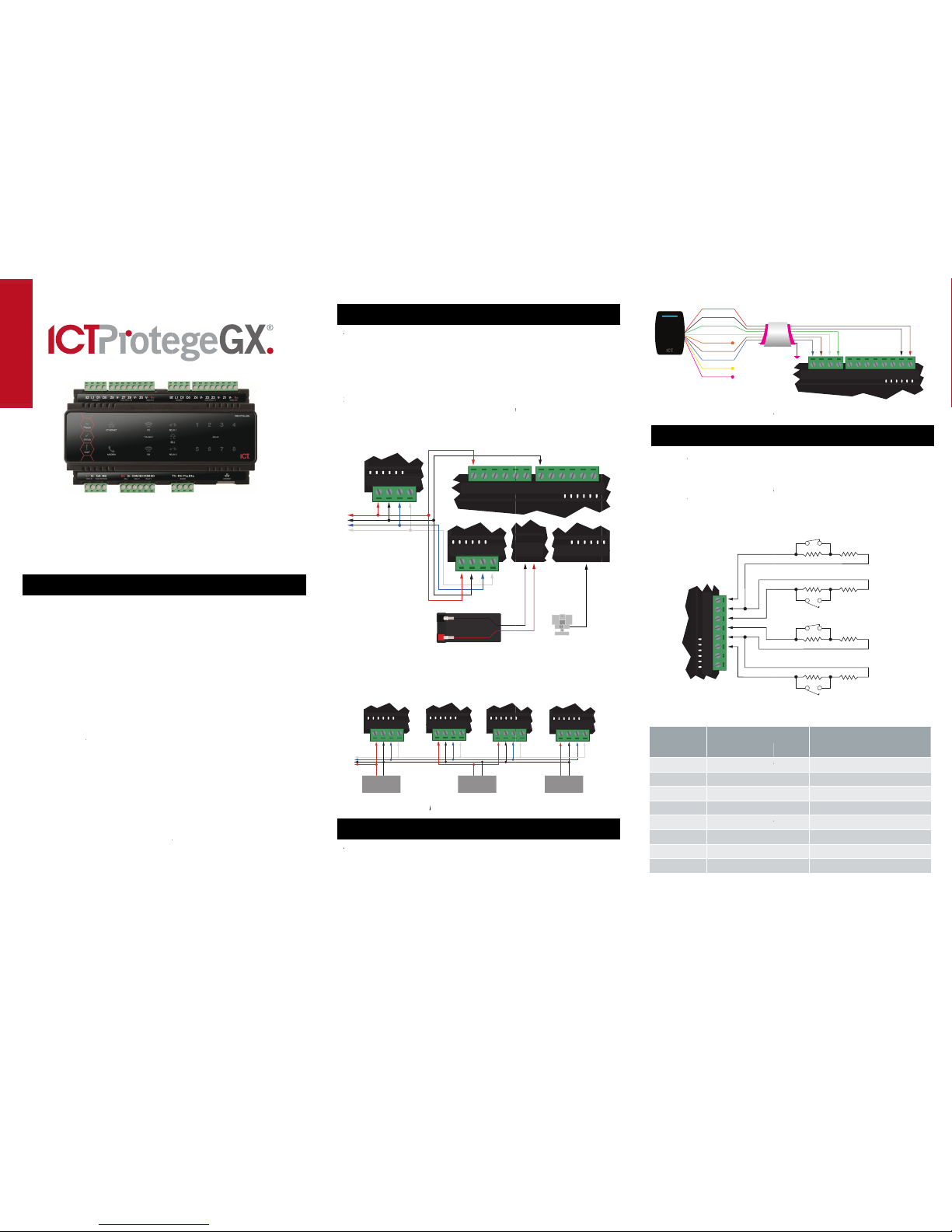
2. Power Requir
e
he Protege GX Integr
C power supply conn
o
ntain internal regulat
RT-PSU-DIN is used
a
me power supply ca
n
ell, so long as the m
a
x
ceeded. If using the
ackup and can be co
n
onitored supply. Ple
a
anual for specific det
a
Exam
p
larger installations, t
h
r load sharing betwe
e
Exam
p
3. Card Reader
C
he following diagram
eader with the GX In
t
ccess Door in Entry
o
ual LED reader mode
ED mode. Refer to y
o
etails.
PRT-CTRL-DIN
NAN+ N- NB
other modules
on network
Module #3
NAN+ N- NB
Power Supply #3
ments
ated System Controll
e
ected to the N+ and
N
ion or isolation. It is r
e
for this purpose. In a
be used to supply t
h
ximum load of the po
w
PRT-PSU-DIN modul
e
nected to the modul
e
se refer to the PRT-P
a
ils of the connection
s
le Power Supply Co
n
he power supply may
n several supplies.
p
le multiple PSU Con
onnection
shows the connectio
n
egrated System Cont
r
r Exit mode. The Con
and readers must be
ur card reader docu
m
NAN+ N- NB
Gel Cell Backup Battery
+
-
V1+ V1+ V1+ V1+ V
1
Module
#
NAN+ N-
Module #2
NAN+ N- NB
Power Supply #2
r is supplied by a 12
V
- terminals. It does n
o
commended that an I
C
s
mall installation this
e module network as
er supply is not
, it can support batte
network to provide a
SU-DIN installation
.
nection
need to be split to all
o
n
ection
of a standard Wiega
n
oller controlling an
troller does not supp
o
configured for single
entation for further
B+
B-
LN
PRT-PSU-DIN
V1+V-+
V- V- V- V-
V-
Mains Input
#
1 PRT-CTRL-DIN
NAN+ N- NB
NB
Power Supply #1
t
T
ry
w
d
rt
4. Do
o
The Prot
e
of up to
4
doors. E
a
that is a
u
The follo
w
door pos
and Alar
m
Input
Input 1
Input 2
Input 3
Input 4
Input 5
Input 6
Input 7
Input 8
Card Re
a
r Contact Conn
e
e
ge GX Integrated S
y
contacts for monitor
i
ch input on the Cont
r
tomatically assigned
a
w
ing example shows
t
ition monitoring conta
c
conditions of the d
o
Door Co
n
Function
Door Contact, Po
r
REX Input, Port 1
Bond Sense, Port
REN Input, Port 1
Door Contact, Po
r
REX Input, Port 2
Bond Sense, Port
REN Input, Port 2
Sh
Shiel
d
RED
BLACK
GREEN
WHITE
ORANGE
BROWN
BLUE
YELLOW
SHIELD
N/R
N/R
Shield not
connected
V+
V-Z4 V- Z3 Z2 V- Z1
a
der Connection
ction
stem Controller allow
s
ng and controlling ac
c
oller can be used for
t
a
nd as a normal inpu
t
t
he connection of a n
o
t to monitor the Ope
n
or.
tact Connection
Default S
e
t 1 Door Contact
REX Input, P
o
1 General Pur
p
General Pur
p
t 2 Door Contact
REX Input, P
o
2 General Pur
p
General Pur
p
ield is frame
grounded at
one point
d
ed Cable
Z4 V
-
BZ L1 D1 DO
N.C. Input Contact
N.C. Input Contact
N.O. Input Contact
N.O. Input Contact
1K
1K1K1K
1K
1K 1K
1K
the connection
ess control
t
he door function
on the system.
rmally closed
, Closed, Forced
tting
, Port 1
rt 1
ose Input
ose Input
, Port 2
rt 2
ose Input
ose Input
V+
V-
-
Z3 Z2 V- Z1
Door Contact
Bond Sense
REN Input
REX Input
Page 2
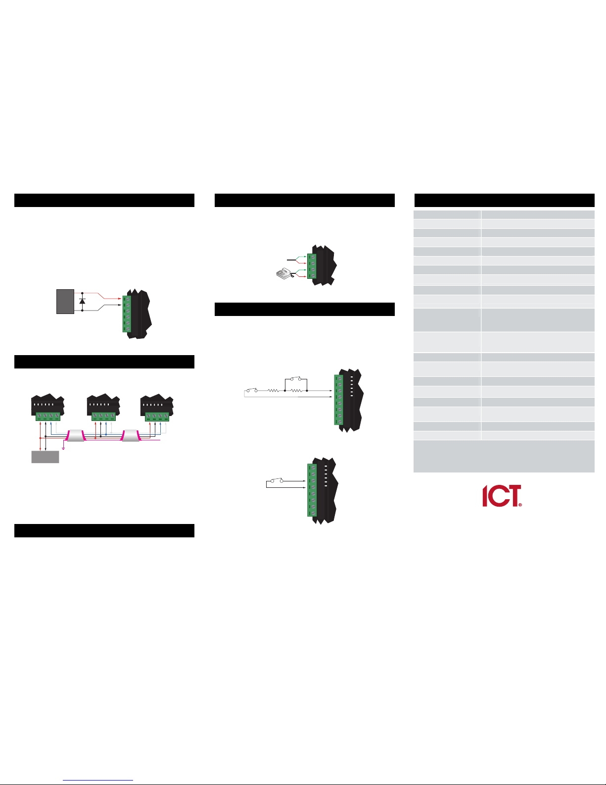
5. Lock Output Connection
The Protege GX Integrated System Controller provides a connection
for one electric strike lock with full monitoring of the lock circuit for
tamper and over current/fuse blown conditions. The door lock
monitoring can be disabled if it is not required.
The lock output is shared with the bell/siren functions. You can select
another output for the lock control (Relay 1 (CP001:03) or Relay 2
(CP001:04)) if the bell/siren function is required. To use the lock
output in conjunction with the onboard reader module, the Lock
output for the door associated with the reader port must be
configured to be the desired lock output on the controller. This is not
configured by default.
Lock Output Connection
6. Encrypted Module Network
The Protege GX Integrated System Controller incorporates
encrypted RS-485 communications technology.
Standard Communication Connection
Always connect the Controller's NA and NB terminals to the NA and
NB terminals of the expansion devices and keypads. The N+ and Nmust connect to a 12V power supply source capable of supplying the
peak current drawn by all modules. If a shielded cable is used, the
shield must be connected at only one end of the cable. DO NOT
connect a shield at both ends.
7. Ethernet Interface
The communication between the Protege System and the Protege
GX Integrated System Controller uses a 10/100 Ethernet network
operating the TCP/IP protocol suite. The IP address of the Controller
can be configured using the LCD Keypad terminal or via the built in
web interface. The default IP address is set to a static IP address of
192.168.1.2 with a subnet mask of 255.255.255.0.
8. Telephone Dialer
The GX Integrated System Controller provides the ability to
communicate alarms and upload information to remote systems
using the onboard 2400bps modem. The telephone line can be
connected directly to the Controller using the onboard telephone
connection terminals.
Telephone Line Connection
9. Inputs
The Protege GX Integrated System Controller can monitor the state
of up to 8 onboard inputs such as magnetic contacts, motion
detectors and temperature sensors. Devices connected to these
inputs can be installed to a maximum distance of 300m (1000ft) from
the Controller when using 22 AWG. The Controller supports normally
opened and normally closed configurations with or without EOL
resistors.
EOL Resistor Input Configuration
No EOL Resistor Input Configuration
10. Technical Specifications
Operating Voltage 12V DC +- 10%
Operating Current 120mA (Typical)
DC Output (Auxiliary) 0.7A (Typical) Electronic Shutdown at 1.1A
Bell DC Output (Continuous) 8 Ohm 30W Siren or 1.1A (Typical)
Bell DC Output (Inrush) 1500mA
Total Combined Current 3.4A (Max)
Electronic Disconnection 9.0VDC
Communication (Ethernet) 1 10/100Mbps Ethernet Communication Link
Communication (Serial) 1 RS-485 Communication Interface Port
Communication (Modem) 1 2400bps Modem Communication
Readers (Standard Mode) 2 Wiegand or clock data readers providing one
Entry/Exit Door or two Entry/Exit only Doors
Readers (Multiplex-reader
Mode)
4 Wiegand Readers (connected in Multiplex
Reader mode) providing any combination of Entry
or Exit for two Doors
Inputs (System Inputs) 8 High Security Monitored Inputs
Outputs 4 50mA (Max) Open Collector Output for reader
LED and beeper or general functions
Relay Outputs 2 FORM A Relays - 7A max
Operating Temperature 0˚ to 49˚C (32˚ to 122˚F)
Storage Temperature -10˚ to 85˚C (14˚ to 185˚F)
Humidity 0% to 85% non condensing, indoor use only
(Relative Humidity)
Dimensions (L x W x H) 156 x 90 x 60mm (6.14 x 3.54 x 2.36")
Weight 376g (13.26oz)
The size of conductor used for the supply of all power to the Protege GX
Integrated System Controller should be adequate in size to prevent voltage drop
at the terminals of no more than 5% of the rated voltage. Specifications are
subject to change without notice, please visit www.incontrol.co.nz for updated
information.
Integrated Control Technology Limited
11 Canaveral Drive, Albany, North Shore City 0632, Auckland, New Zealand
P.O. Box 302-340, North Harbour, Auckland, New Zealand
Phone: +64 (9) 476 7124
Fax: +64 (9) 476 7128
Email: support@incontrol.co.nz
www.incontrol.co.nz
Designers and manufacturers of integrated electronic access control, security and building
automation products.
Designed and manufactured by Integrated Control Technology Limited.
© Copyright Integrated Control Technology Limited 2003-2011. All rights reserved.
227-5045-200
+
-
1N4007 Diode
12VDC Electric
Locking Device
B+
B- COM NO COM NO
PRT-PSU-DIN or
equivalent 12V DC
Shield is frame
grounded at
one point
Shields are
connected together
and Isolated
Shielded Cable
PRT-CTRL-DIN Network Module Network Module
Shielded Cable
Shield not
connected
NAN+ N- NB
NAN+ N- NB NAN+ N- NB
supply
R1i T1o R1oT1i
Telco line out
Telco line
tip and ring input
N.C Input Contact
N.C Tamper 1K 1K
V+
V-Z4 V- Z3 Z2 V- Z1
N.C Input Contact
V+
V-Z4 V- Z3 Z2 V- Z1
 Loading...