

Page 1
℉℉℉℉℉℉℉℉℉℉℉℉℉℉℉℉℉℉℉℉℉℉℉℉℉
℉℉℉℉℉℉℉℉℉℉℉℉℉℉℉℉℉℉℉℉℉User Manual
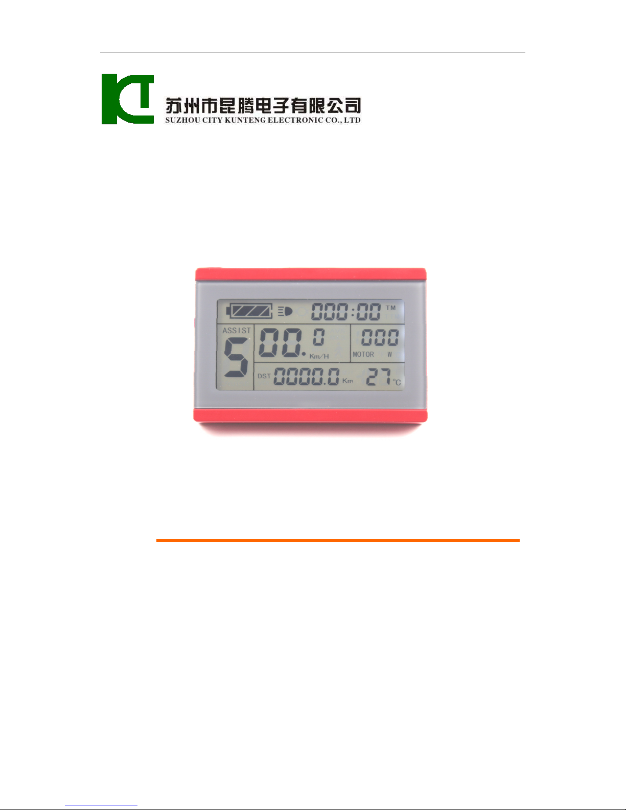
KT-LCD3 eBike Special Meter
WWW.SZKTDZ.COM
'г
""\
±
ЭЁШҐПЁЁЕЗЁНЕЪЕІ
ЅПІІ-[ОП
СІТУ
КШЧТЕНС
ЕЬЕСТКОІЧІС
СО..
ЬТІ)
\
›
fii'l'|fliEfl§E§EflE£E|
SUZHDU
CITY
KUHTENG
ELECTRDNIC
C11.
LTD
I
l
Page 2

ELECTRIC BICYCLE METER KT—LCD3 Product User Manual
- 1 -
Contents
Preface……………………………………………………………………………..………. 4
Outlook and Size…………………………………………………………………………... 4
MeterDimension……………………………………………………………………… 4
Button Box Dimension……………………………………………………………….. 4
Main Material and Color………………………………………………….………...... 5
Wiring Schematic……………………………………………………………….……. 5
Installation Instruction……………………………………………………………….…….. 5
Φ 31.8 handlebar diameters install icon………………………………………..….… 5
Φ 22.2 handlebar diameters install icon……………………………………….….…. 5
Physical installation icon............................................................................................. 6
Function Overview……………………………………………………………………..….. 6
Display Content…………………………………………………………………….….…... 6
Button Definition…………………………………………………………………….….…. 7
Normal Operation………………………………………………………………………...... 7
On/Off…………………………………………………………………………........... 7
Display Interface………………………………………………………….….……..... 8
Display 1………………………………………………………………..……...... 8
Display 2……………………………………………………………………...... 9
Display 3……………………………………………………………..……….... 10
PAS Ratio (or Handlebar) Gear Switch……………………………….……………. 11
Push Function…………………………………………………………..…………… 11
Cruise Function…………………………………………………………………...… 12
Turn On/Off Backlight…………………………………………………….………... 12
Battery Capacity Indicator…………………………………………..…………….… 13
Motor Power and Temperature ................................................................................... 13
Environment Temperature…………………………………………………………... 14
Single Data Clearing……………………………………………………………….... 15
Page 3

ELECTRIC BICYCLE METER KT—LCD3 Product User Manual
- 2 -
Automatic Prompt Interface……………………………………………………..….. 15
Error Code Display…………………………………………………….…........ 15
Motor Operating Temperature Alarm……………………………………......... 15
User Project Setting……………………………………………………………………..... 16
General Project Setting…………………………………………………………………… 16
Maximum Trip Speed………………………………………………………….......... 16
Wheel Diameter…………………………………………………………………..…. 17
Metric and Imperial Units…………………………………………………………... 18
Exit General Project Setting……………………………………………………….... 18
P Parameter Setting……………………………………………………………….…….... 19
P1 Motor Characteristic Parameter Setting Mode ...................................................... 19
P2 Wheel Speed Pulse Signal Setting Mode .............................................................. 19
P3 Power Assist Control Mode .................................................................................. 20
P4 Handlebar Startup Mode ....................................................................................... 21
P5 Power Monitoring Mode ....................................................................................... 21
Exit P Parameter Setting ............................................................................................. 22
C Parameter Setting ............................................................................................................ 23
C1 Power Assist Sensor and Parameter Selection Mode ........................................... 23
C2 Motor Phase Classification Coding Mode ............................................................ 23
C3 Power Assist Ratio Gear Initialization Mode........................................................ 24
C4 Handlebar Function Setting Mode ........................................................................ 25
C5 Controller Maximum Current Adjustment Mode ................................................. 26
C6 Backlight Brightness Adjustment Mode ............................................................... 27
C7 Cruise Function Setting Mode .............................................................................. 27
C8 Motor Operating Temperature Display Mode ...................................................... 28
C9 Power-on Password Setting Mode ........................................................................ 29
C10 Automatic Restore Default Setting Mode ........................................................... 30
C11 Attribute Selection Mode .................................................................................... 31
C12 Controller Minimum Voltage Adjustment Mode ............................................... 32
Exit C Parameter Setting............................................................................................. 33
Page 4

ELECTRIC BICYCLE METER KT—LCD3 Product User Manual
- 3 -
Parameter Copy .................................................................................................................. 33
User Setting Note ............................................................................................................... 35
Version Information……………………………………………………………………… 35
Page 5
ELECTRIC BICYCLE METER KT—LCD3 Product User Manual
- 4 -
Preface
The illustrated manual will help you understand and be familiar with the meter
function, guiding you on how to operate the meter, how to set the project parameters, how
to achieve the best match of the three as motor, controller and meter to improve electronic
control performance of the electric motor. This manual covers installation, operation,
parameter setting of the meter and how to use it properly, which help you resolve the
problems appeared in practical use.
Outlook and Size
○
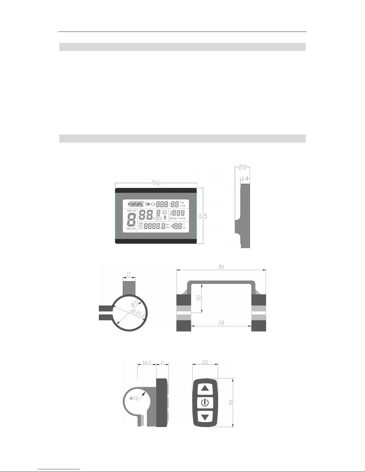
Meter Dimension
Meter Dimension
Dual Bracket Mounting Dimension
○
Button Box Dimension
З
96
14
3
из
131!
сп
аіїї
Ё3
Ф,
:с:
О
ОТ
1%
гг0На
вввв.в:нв
_
56
_
72
ї
Эд
-А-
їЄ>,З
11
83
Ф22
@515
O,
1
\
1
(DEE
*1
6.3
9
6
|
86
~;2
58
11
E3
LO
‘<1’
Page 6
ELECTRIC BICYCLE METER KT—LCD3 Product User Manual
- 5 -
○
Main Material and Color
PC material is mainly used for KT-LCD3 meter and button box housing, and the
housing color is dark gray or white.
○
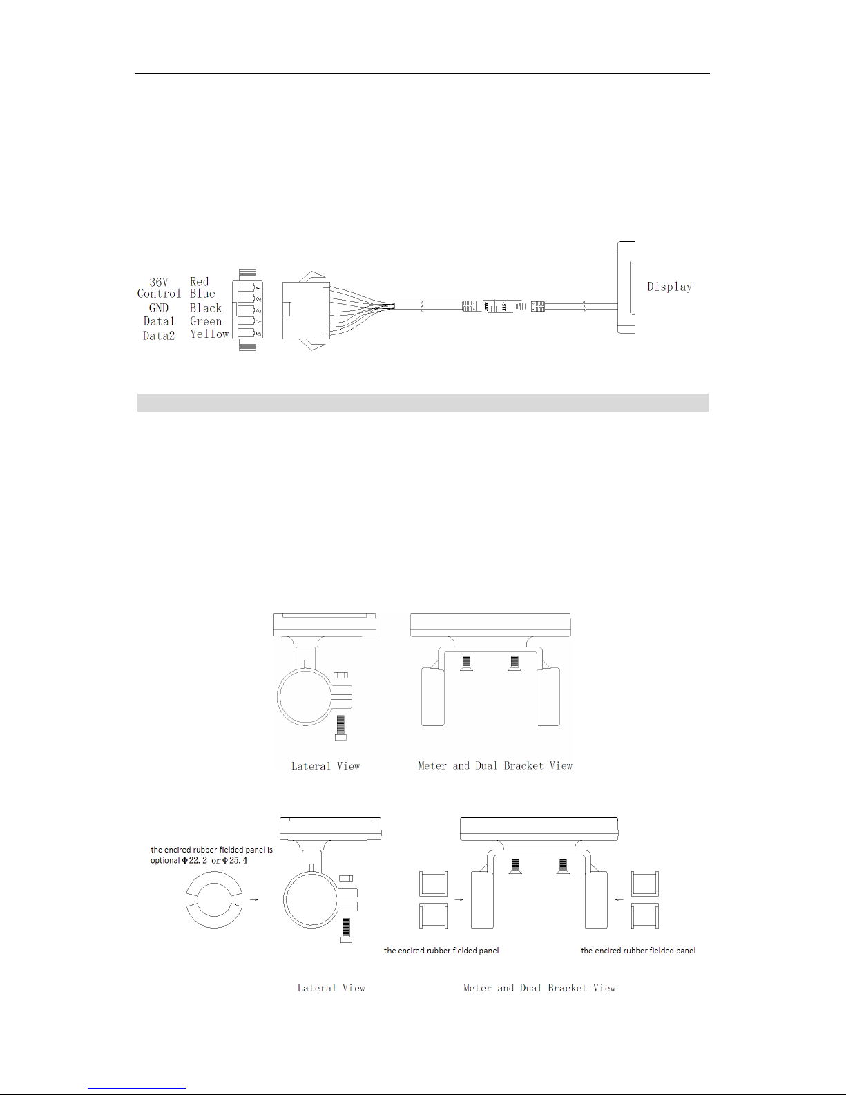
Wiring Schematic
Installation Instruction
The meter body and button box are mounted on the handlebars of the electric vehicle,
adjusting perspective. In the case that the vehicle is power off, the meter connectors are in
plug connection to corresponding controller connectors. Turn on the power, electric
vehicle and meter will be under normal operation, the meter installation is finished. The
protection film on meter display panel should be torn.
○
Φ 31.8 handlebar diameters install icon
○
Φ 22.2 handlebar diameters install icon
с\1э
в1а<:ъ<
Ш:
||
“Ё
«
Ітнідшіінн
»
зєу
нед
Ё
/^
.
Соп'Ёго1
В1ъ1е
Ё"
-\
В1Ѕр1аУ
Ва_Іа1
Сгееп
їёч
Вдтд2
Уе11ош
ЁІЁЮ
.
У
(Не
епсігеб
гиЬЬег
їіеісіесї
рапеі
із
ор±іопаІФ22.2отФ25.
4
Єёд
І
Ё
Ш
Ё
Ё
ШШ
ЬаЪега1
Уіеш
Меїег
апё
Вцаї
Вгасйет
Уіеш
І ї
Ш
Ща
Ё
Ё
ЄЩ
%ў
Ш Ш
Шшпшшп
(Не
епсігесі
гиІ:›Ьег
Тіеісіесі
рапеі
(Не
епсігесі
гиызегііеісіесі
рапеі
ЬаІега1
Уіет
Метег
апд
Виа1
Вгасйег
Уіеш
'r
l
Coifiiol
gifie
Egg;
Display
exp
Black
Em
I
Illfifilll
"ll"
~11
K:}v
Datal
Green
D3152
YE‘-110W
l:l"'-l
:
%
%
optional
<l>22.2or<1>
25.
4
\
W
EB
lill
lLLi
Lateral
View
Meter
and
Dual
Bracket
View
ll
'l
l l
the
encired
rubber
fielded
panel
is
N
K
6%
E
U
U
fiimnnnll
the
encired
rubber
fielded
panel
the
encired
rubber
fielded
panel
Lateral
View
Meter
and
Dual
Bracket
View
Page 7
ELECTRIC BICYCLE METER KT—LCD3 Product User Manual
- 6 -
○
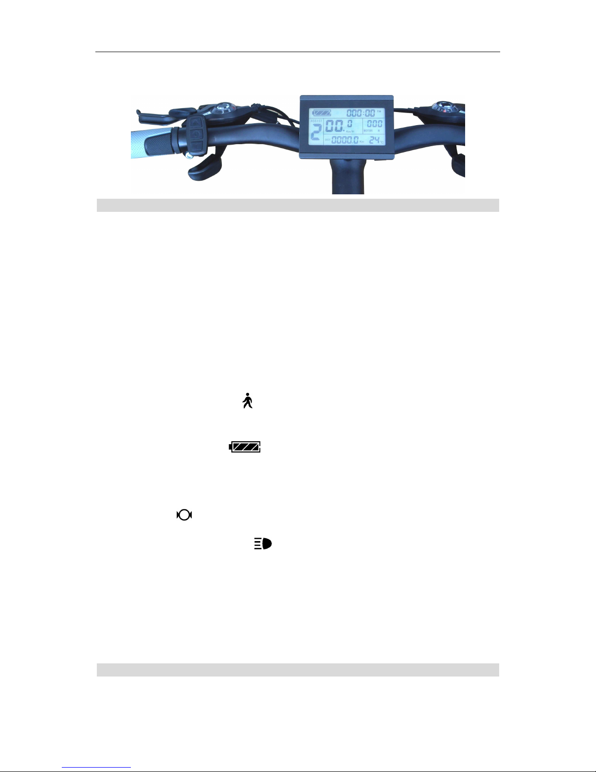
Physical installation icon
Function Overview
KT-LCD3 meter provide you with a variety of functions such as vehicle controls and
vehicle status digitized displays to meet the trip demands.
Trip time display (with displays of a single trip time (TM) and total trip time (TTM));
Trip speed display (with displays of real-time speed (Km/H or MPH) and a single
maximum speed (MXS) and a single average speed (AVS));
Trip distance display (with displays of a single trip distance (DST) and total trip
distance (ODO));
Power assistant ratio (or handlebar) gear (ASSIST) switch;
6Km/H power assistant push ( ) function;
Cruise function (CRUISE);
Battery capacity indicator ( );
Real-time battery voltage (VOL) display;
Motor power and temperature (MOTOR) display;
Brake display ( );
Turn on backlighting and lights ( );
Environment temperature ( or ) display;
Data clearing;
Fault code display;
User parameter setting
℉
24V, 36V, 48V supply voltage can automatic identification and be compatible
℉
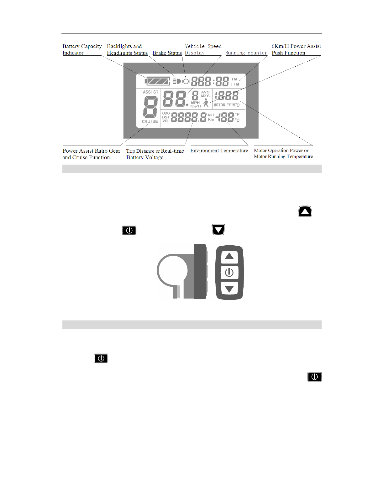
Display Content
The display content is shown as follow.
ЙЫ`
Й
Ч:
п
дм
Д
І
І
гы
Ц
М
др
“PU
V
7%
find
M
Wm”;
7"
an,__'r_
_._’__U”‘_
_
_'._
_.€>’‘_
0’
_‘
.._
‘
_HU_
M
mm‘H_“FL
_“H___H_
‘_
>03
W!‘
‘H
_‘_
‘|‘_h‘
‘L
Page 8
ELECTRIC BICYCLE METER KT—LCD3 Product User Manual
- 7 -
Button Definition
KT-LCD3 meter adopts the structural form with part design between the main part
and operating buttons.
There are three keys on the operating panel of button box, which are icons of
button (alt text UP), button (alt text SW) and (alt text DOWN).
Button Box and Operating Panel
Normal Operation
○
On/Off
Hold button (SW) long, the meter is powered on and into normal operation, and
it provides the controller with power supply. Under normal operating status, hold
button (SW) long, the meter is powered off, meanwhile to shutdown the power supply of
controllers. When the vehicle is stopped and without any button operation on the
meter for five minutes, the meter will automatically shut down, and the power supply
of the electric vehicle will be powered off. In power off mode, the power consumption of
the meter and controller is zero.
Вайегу
Сарасіїу
Вас1<1і3І1ІЅ
апсї
\/е11іс1е
Ѕреесї
6Кш/Н
Рош/ег
Аззізг
Ішїісаюг
Неас11і;11гз
Ѕташзїгаке
Ѕгашз\
Візріау
Кпппіпз
соиптег
РНЅІ1
Рппстіоп
Цї¦ё››о«
З:2ВП^м
АЅЅІЅІ
і-':\\/3
'
Ё
ф
ф
О
М›іЅ
'
Ю
Ц
Ц:
Дит,
Й%|ь1к“ъш'^(;
её
/Ш
/
\
Р0\Х/Єг
АЅЅіЅІ
Кайо
Єеаг
Тгір
ВізгапсеотКЄа1-Іі1'І1Є
ЁШ/іІ'0І1шЄпІ
Тетрегашге
Моїог
Орегаїіоп
Рош/ет
ог
Моїог
Кшшіп
Тетрегашге
апсї
Сгиізе
Рипсїіоп
Ваїгегу
\7о1Іа,<;е
Ё
СІЕІІ
Battery
Capacity
Backlights
and
Vehicle
Speed
6Km/H
Power
Assist
Indicator
H{<flights
Status€rake
Status\DiSD1E1Y/Running
Conn?
Push
Function
/
/
\
Power
Assist
Ratio
Gear
Trip
DistanceorReal-time
Environment
Temperature
Motor
Operation
Power
or
and
Cruise
Function
Battery
Voltage
MOW"
Rlllming
Temperature
GED
[
1
at
at
Page 9
ELECTRIC BICYCLE METER KT—LCD3 Product User Manual
- 8 -
○
Display Interface
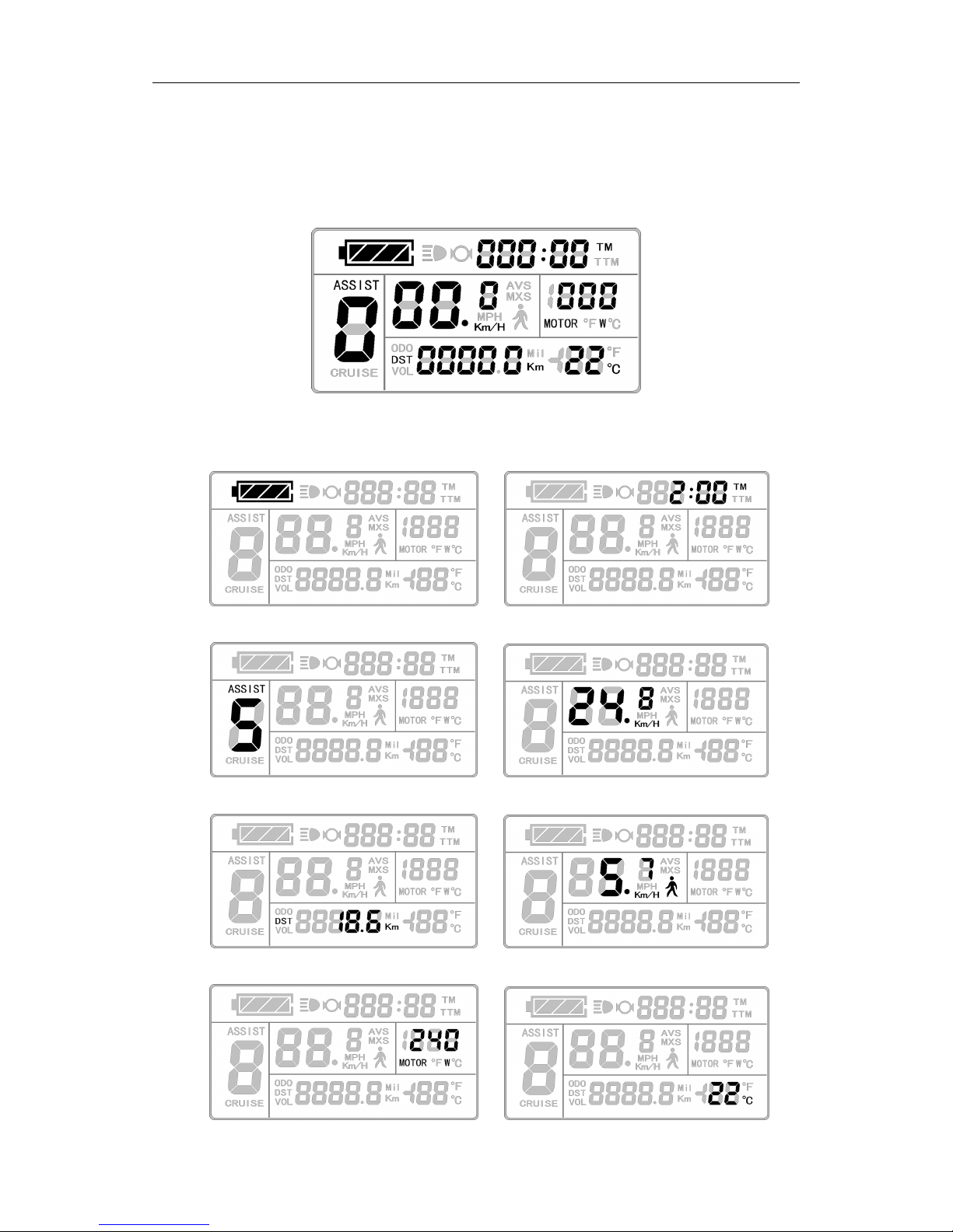
Display 1
The meter is startup to enter display 1.
Display 1
The followings are shown on display 1.
Battery Capacity Indicator Single Trip Time (TM) Display
Power Assist Ratio Gear (ASSIST) Real-time Trip Speed (Km/H)
Single Trip Distance 6Km/H Power Assist Function
Т
лм
пи
“Ц
пи
тим
“ин
Пит
_'Іы
:
мины
ш__
Ш-
“атм
И
_`_
С
О
ча
пт
пипи
В
пи
1ТЬ
ЕЅЁ
__<В_
%
{
С
/
\
щщ
_*
В
Н
ВМ
__-Ш
И..
Ґ:
чдь
\
і
Ш
`
К
В
В
ІІ
Т
__:
Ш
___:
ди
пи
|\
ї
Ж
Ё
паи
ЧК
чат
Й
И
\\
T
M
T
M
0.1
ll
0.1
uu
T
inPH4;»
all
,
,
°
Knv1{rWL
MOTOR
rfwie
Q
P9!
ii-Ii
til
H
‘lnli>lL
Q
E21
U
I23
‘
:0
I221
E3
‘l
I"
»
_ _
— — —
§
ASSIST
‘III?’
ciefi
\\.
\\
K
\\ //
7";
l
rrni
°
n;u;n
rrln
TM
wr.Y/\Y,
u
rel
llwrlll'l
l
TE"
W
l
“T”
_.,l
FY31\/vile
ri_r,
vile
l
lli“;/>~
>>>f<Q:;e>l‘l~‘§~%’>
»‘%~i*~
l~“=?’~
llllLl,l’;i7l"]
fi\;lfl,_~*=;¢>_>illl
l l l,ll l
,'
pl
l l l,,
l
£1
‘l
l
“,~=,‘
V,/'=_
5’
l
l
l
M
fil
E1
lll l
l l
l
/A
M
llll»
ll
All
n;ln;ln
n
lll,
r:.
~
an
ll
ittilrinii
llojlji,/ill
liinil
Z)
l
l
(Q/lg’ll/ll;
llll
lllij
e
l
l l
l
Pal
l‘j~w”llli7~lr*lllrrjl
lwil
lrrilinil
ll/l
lllA:7Wl"/V}
l
E’/l
’F
Tl/”l;\L
ll/<)Tlilll¢l71l\llll‘l#LLl~
l7Ll41\lMnlll
‘*
T
~FllH===E
u
we
4 \\
QWZIT
l7T7<*I1>:'
;<:§>:'
“>¢:%<
>i:;>;\
i>si:;>;fby1»::;<\
:;z;;<‘
;;i:;:~:
?>1i‘:j>:
i:;;;;
:<::;¢:,’,t¥fi!:\
W
A
o
llll
W
3
iw;
l,¢l_l,€ll€;E§ll,l_lt,l
liglitgl
UQIW
rllrlpvllégll
~;F‘A<1’;
>1.
\‘
O
lefilawmflfifiwflim
lnafiemmfififimflfiw
TTM
rrln
4%“
,\;;,
[7‘J_/‘~\_\“~_,wji,
J‘K7*(‘W?
(
ASSISTMit
H
Wp
“l
\%ri¢*ie<
@;lM%@
nnnnnnn
rc_»l
lll
l_
T
Q
lll
l
l
Ci:
J.
“ll°Km/H
\
‘l‘lllllll
H
ll
iTU
llmlturlril
lal
LJl@e":nnnnnn1
nine
"
W
it
ll“
ilinrnn"Flllll
”“E]]"C»‘~
/T,
‘D‘J!
xjyzz,
wjid
L
‘
I
l
lll
ll’ll
JF
l»»,;;;;,,
‘\1t~_--If‘
Et‘
‘Vri:E.;:y1*v,
J
»llll?’l,iTlfllJfll’@lT'lT,lF¥‘
W
,/
(lllU
lg,M,i
W,,\\
,
Mun
7_
,l~lll l’
mmlll
Ll'lLll
lgllifg
Uiugyflwngg
e
lLllll_l.lll,l_lr_lllV,»_,,l
l,Llr;l
Be
A
l/\\M,-Xl,»,
“\,//’;’/llll.,.;>’l
‘kltI/Ym
‘Kt
l
l
'V\/y4;ye
B.g:JUU/U=U
AU~:Qu
tg
J
/
,1
’:
ii?‘
\AV’'&7”‘\'5
/‘l,E
l/:§\‘_i,¢//
*’&~<é,;:/7”‘
@
T‘T}'5
l l
ll‘
"Kn
,~'A\§/J’»>1
\
l
‘
(H
‘/~€,,¢.K
{Man
'
"',_l.
llll_l\ll’utl_rl,\
lp;,l_tp,l
Er»-oiri
l_l
‘G
[l3FQll:liH‘lil”<iJlL
4%‘
or
//
t\
l
‘l
lllllll‘
l
l ll-in?~H
_t
,
i
el‘era
,~;l~l\‘
ll/lll_llTLllF€
F
n
O
Km/H
_
"K
f f
l
7
T
E‘/'e~lt\)
J}Ol\l*[,';l
iim}
\\
//
T
/El
E“
l lll lll
l l
l
lmrltgT”H
“TITlii
ll
liil
iJ
crow:/,1
1 1v‘l‘vIIilI I
)1
/Tiliyi
,,\
_
,
il“g\i'L-:lll1:1lliK‘;;)l\Tl_\/‘llfl
ll
lx/‘,_1\Uli/l_iU
L7l_L,,
’
._
l_
li’
l_
_
l
l
11
l
l
l
xl
C
/T\
'?
'rl—'\_
l
lAl
M?H
fl
llllll‘1lTll‘llRMFlulllltlitlé
DST
f:;;:;§
j::§:,;}:f
V315:
:
_
/~
Llllnrll
l
a
Ll»
,_r
l,,\it
r
”*"
*3
l~J
l_l;:;FlUUll»
l.:,l)L
>
~~~
Gll
U
T
.5-1'
D;/I
n
rr ll~
“Ul*”CWW“DWU1WFrjWTMQPn
V
_JlJLl
7
\\
'>--
/:\
,-;,>V-as
;,>\
V
iii
f
iii
4 4
i i
a
an
lilg
:
If
,.~
;:\r\\‘
via
,
_l
,/H
ll:,,P.
u
on-tglniazl
ll~47lIll l
rows
vi,IJ
K‘l‘l’IK‘l
l
,,l
‘ll
lllll‘
M
W
ii
lll lll\pl"“*l'"yLl/’*»>s\V~‘
l,‘Ll<_
ll
lll
lllll
l r
,
lll lll lll lll_
WPH
~:i<l
til
a
l
Il»"?*1>a,
ll:l";Ll,7~}"‘\
re"
“‘](l'
L‘
L
pi
~\
l
T
i,
MOTORFw
TM
\‘
0
@[~\_§ljl]llpj*_l§/l
(:1
l‘_j}l:lV4ll\j_l\:¢,l
TM
TTM
rrn
(éblliidH/\E;\i";El“l
‘l"iil:¥>‘\_i:;?":
‘lll
‘Cww1>llI‘Ff]‘J
[ f
iW711
lizjsi
‘:<I;>;’
L‘
ll
ll
,
HlimilfirulLlllnlrl
ll;l7l;\,l
legal
TT7I
\
l/llllll
l,"»'/
‘iii
1:Wtowrrt;l
-\
l
T
>
ilinrlon-Flllll
tlllllll
LA»
lnrll
,»/Ll1\llll/¢lT‘li_.l“
ll'{iJ:\lmi
ll
ll
*7»W‘~‘~;al»‘L.
ct:
<7:
its‘Jlit?
Y
/1
\\
T
l
llr
l
7
7
l l
~>I1‘
‘
rA:ft
<6
J1‘y
(L
»:r\én,;:~‘
(\é,,-
‘l;__,,;~
rsli,»
»\__M,;>,ID
/AM».(l
it
ll‘ll
llll
l
l
l1
l
llll
llll
lill
ll
Mil
_
F
E
U
QC
4
~;F‘A<1’;
>1.
\\
//
Page 10
ELECTRIC BICYCLE METER KT—LCD3 Product User Manual
- 9 -
Motor Operation Power Environment Temperature
Backlights and Headlights Status Brake Status
Cruise Function (CRUISE) Motor Running Temperature
Display 2
In display 1, hold button (SW) shortly to enter display 2.
Display 2
The followings are shown on display 2:
Total Trip Time (TTM) Total Trip Distance (ODO)
`і/
О
д
і
\і/
/И
\і/
_.:
Ю
га
К
/И
\і/
Е
Ѕ
_
_Ц
-,ш
/И
. {
____
їм
ЛТ
пт
ПЦ
лм
НЦ
НЦ
ЙЦ
:_\
ЗА
БМ
__
_О
__|
ы`О
\\м
Ѕ13умМАХ
“атм
чі
_..Ь
ІІ
р.'_
ї
__С
На
ча
_
Атт
ПШ
пипипи
пи
ОТЬ
В
_
0____\
\і/
і
\і/
44
ШЁ
Ю--+
щ\_Мщ
34%
М_Ган
М
т
ИК`` `
В
А
В
8
ІІ
`_
О
"
`
В
О
д_
М
і_
БМ
_
'Ь
_
Ь..
_
_.:
\і/
/И
\і/
И
/Ні
“K
(\
\‘
0
:
=
TM
=.
TTM
lo‘
rrln
\\
llI
l
ll
Wm“;
lll l
l l
rift»
_.e.
l
l l
I
l l
l l rIifiling“1Tr:
TR;
a‘~
IA1;\€';T,
lllIllTll
I»*I]4I;>%I
U‘lifl}i¥1;§§>
lll
B
I
\;T/>4
\T;:,
/T
‘Trll
l l
l
l
I
ITTTl»TII*II,.I
TT»
/A
7
,/\
ll
l
I
T
l/[H
’//‘lll'7F@
‘CK-
TQup
Q
T
l:1i~
_
lIlI
T
I
l\,;I'/l'7“l;:\,/"
ll'j7fi?i§i:*i;¢
\Qi1-J
k/l
0’
ll);
lulL4\_l
M
H
/II
/I
AIIA
‘Z
i
/tr,/
._
T
~l"ti>
lagtlllalgrr;
it
;iT
@§E§,T
I
T
T
‘l
_ll_lll_l‘
lo“
llll
T
u
\ll@L
lbl
l<Ll
~r~_o>l@Um~l
~l
liCjF:‘Ll
1
//
\\
_
Itlfl
,:\
If
/nA
\lIIllIr
—
;»TE\l'
T"\'2K;>
r
l
lll
l
l
l
ll’
‘lol/~
\
l
D
‘
l
lolnlli;
l
l
lll
lllllllllllll
ll
JF
l1?5Ll:T/lll:£lll71L\‘l
lnllnll
ll
T
w7,L
lTLl
lll_lLllll;ll;Tl_ll
rii-ii
»lTvll;TLliIl
lpntl
\'
D
T/“
‘-iiI¢"I
REF‘
//
\“ ”/
TTlillil
3
~\\
ii
"TT
: :
5
rr
U1
nll
/I
,1,I
,¢I_,>,I
,tI_,>,I
III
TKT TTT:“
CQJ
ttn
l l l
l
>»i<
.ll l l
. .
Lll///!\l¥‘(\ll
ll llLl
lTl_rll
l_Ll
l
,
T
a_T
I
I I I
II,_,l
I,
fl/exT5;3.n
V
I
I I I I I
II,
-,I T,
I:
III
\/
_
r
r’lWH~’~l°
lllllnlrl
ale
lll
we
’ll/llll
MTFH
l/ll
lll°
/‘~:\
T7“
lx
l l‘l
‘
ll//ll
l_>_\,l
l/rillNll,>,,
I,
I‘//’
S4,,
1;
/\,¢
IV‘
III‘II\LII_IT7II:I_III,;Tl’|%]
(I,Al_lll
V
/
I
*IfIl
l
—~~,=
,T.
I3
n
QRU|SE
l
tr
E
1:inn
"Tl?
V
Te
'
Cl
lTull?J
lTu
.
W~"l'i\
\‘l/'‘J"iiJ""Ki
Ml
‘<~
=2»H\=»
we
l—\/\7
l,lIl
,
L,-\TI.\L,lQL,]
12,;
I
II,,
I
l
lll
\
?\
<?\
Al-
ljil
MOTORFc
n
ll
iti‘“
T‘i‘"Fl
KY1
lTil:lTTilllll_ll§;lli ni;ll
TTlT"
llllT"lll/%.lMllnn
ll
lo
klFlll
llll
// \\
[
T
at
\\
//
Q
0
§Il’“‘=»I
l/ITr1":*;I»
If
V114:
,3G_
I
<1‘7-
‘CI
-J
O
ga
e
<1
7/
__
,
I’!
AV§
lfi
jl
9l"lgl
l"l
M
H
MOTOR
ale
llll
°c
Q1
5;!
E3354
TM
T
TM
T
I
-a-‘e>TTJ
’
rnnnr
‘
u
‘llll
ft
il_
l
“EC
Eu;
Tl
l
lil
\\
\\
2|rm/1»
Sf
‘I
~;f7”
§.lTi»*
*‘~l‘:\;~;ill“~
l
is
l
“
/T//\\
.\
1’l:1’
iii’
‘,1’
*7
\,'\I
\;~fil7
IIIIIII
-.
/‘Tet;
‘xv/4//’;l’Tli1i_;‘
l
l
llIlnlela
'5'?‘
can
J
//
rr
l
rln
N“
//
_
//V;///////V///y/
'VVVVV;//£///////y/
IIIIIIT;;;T
_IWI_Il_IIII
I
I
it
ttn
llT§Ll;l‘
l
l llIl
I
I;:;I_It.»:I
\
T;.lI;;l\
//lFl
B
kg;
\__
l
L
L
Ili\*Ix7Ir”Il
Jr“/=‘~u\\!I/ti:/15],/l-
, I
lllll l
l
l:~ll*ll~.l
l>~l:§1~.l
lTlT
*
,
ll ll
llltnulltl
l,e»sTTl
lTetl
é,K
IlIlIIITIII
I
II___IIIII4,4
TYT
l
/'~\
.:=l\linl'jl~,¢\
l
lTll
/
»»,
4:6]
lllllPl
lav\l5
l7§l,,':\
are
llll
nllulTlulR
are
n
/
\\{
uu‘ll@L
lrlrtlal
l
il
‘
i
I11ZIiP1'
iisijiéri
i1si:;>1f
iIsfi;T¥I'
<
V
*lLl
lllll-T
lTLlll‘rmll,l_l
lg’
T
orla\;
l'll‘lrl
ll
TT
>1i:I;>rf
if§;;%1T
I:III:I
/‘\-7!"
all
"La
u
T“lillll@lLl1:”Tl“>ll1?’T
lTl
»
ale
l
l
°‘Z%
Clnn
:»léi;l
J
erlre lr
lTj;Tl:l;Tl
l
_QKm
Til
5..
L
lg
:.0U
4 \\
til
iii
iii
J
II‘XI,<\l\;:faII
re
lli:l‘—l?l/lll\ll:l4/llll
mlll_llllill
TM
TtT
: :
5
[Tl
Tl
‘;::l"§:i
):;_::;I
‘T>;‘_I;~=:j_:»:_<>i
l
/
ll
llllllll
lIll,I_
TM
// \\
“K
rr
zeFlLl
l‘lil""l*l'l‘lill’lTrln
4 4
_ _
e
;
T;
Jjwl
l_lIIIIlTI
H
eT
~
»
finial
nil
Q7‘l*~,
n
l
11:1
04.1
\_f5~
IITQ<1ii;“
‘;r;:T
l
/
\//
~
//\
TI
lLlTl
U
l
T/111555?
,,TjT’IIIf3
I:IlTTl“
liéif
l‘:<'fl
‘:1!
T521’
‘Tl
3;’,
fa?
U
TTlillil
l
1'
ll
ll
rMLlllllLllllIlIII,tll,Tl
t_l
lT\Ill(,,l
tIll,LtLl
‘@”l/Q
ITIIFMUE
// \\
“T
H
l\“I;*Ir’
_lj#.u
\Ul'/"P;/l/I4I
lllllIlqflt,T,'?\l?,<2,;
T
’ l'’‘l
L
ll
lti
I'M
0
,<M,fqH|
llnlrnn
lsll
Ilfr
Il
l
l
..
__T
.<_
_
_
l.4%,lrJ;
,
\,~
\\;/VQ/-N,
I
/wt
T/‘rmtT1
\.l
lgrxul
l
ll
IQ!
ll,‘
ll’ill,En
II\I
_
<:>
l;’~l1i,
MOTOR
‘re
°c
\\
‘llll
ll_tl
Dt~>Tru*u
l_ll,,,l_l,lT(II;TTl_l&Il
TlF‘W
/G
lylllj,l‘L/5if
‘:~»'I
M5"
fr.
I7”ID
\‘
Pl
tr
.,.£;.~
'\
lsqi/j;
@
/IatITA
//
./
r,‘)\_
//
Page 11
ELECTRIC BICYCLE METER KT—LCD3 Product User Manual
- 10 -
Single Average Speed (AVS) Motor Operating Temperature
In the riding mode after 5 seconds, display 2 automatically returns to display 1.
℉℉℉℉
In display 1, the original motor power is replaced by motor running temperature as is
shown in Figure.
Display 3
In display 2, hold button (SW) shortly to enter display 3.
Display 3
The followings are shown on display 3.
Single Maximum Speed (MXS) Real-time Voltage (VOL)
In the riding mode after 5 seconds, single maximum speed will automatically
return to real-time trip speed (Km/H) as shown in the icon.
ЗА
Ю
Б
К
Вы
пи
ча
_.:
В
пи
“Ц
7Ы*С7Ы.
С
Ѕ
Ю-,
Ю--
МН
Щ
ти
___”
пи
Ё
С
О
т
К
%
`і/
ВИ
за
Вт
ВМ
-
.
ГЦ
2.1
Іь
И
іі
па
М
“__”
ча
;
\
//
\-\
i i
TM
T T
rrllll
6:;
czl
cm
czlczl
ASSIST
la
-_F
V‘
ill
iii,
MOTOR
’
'
lliliillllil
l
_
,__
‘-"1
l.~.l
Q
nil
-J -J
'
Q
E-J
51.!
z
lplg;
ll;
3:~‘4*_
,4,
Va;
C5’
\_\
[
T
at
\\
7/
:||:'|
TM
LQLI
TTM
lfzl
£11
ca
'1
iii
fee_Tl/111:5
._
lilllIuu
‘T?
7
i
lillIll
-Il.
ll,‘T
i
_
nill._/
'
\\
VIIA:
ASSI
P
:
III
‘
0
Ill
MOTOR
lHE
VOL
//
ST
u"
-J
l"
Ti?
‘J
3%
E9
ll.lll_l[Tl:l.lTlTl
l
lll,
l
'
7::
yr’;l.lTl
l
l,ll‘
F
-
TJTll~; TIT~I_T<
I
QC
I
_
;
\‘
//
l”'lllgllii:l1lli;:lnil
ll:ll:llTl
rill
Ell
T
Q’
V
l
n
i
If
f
f
ljl
Elill
Tl1;‘
T
lll
nil
ll;lll:lllT:
Tr
___
/llf,
za
l
lo»
l
l
:.
I]
Z‘
-ll
"kl
ow
A
Q
r
l
I
In
5
l
l
éiil
T
llll**“>",‘¥‘
lllI,
ll
’Q'
MXS
Ill._I
I1’I_IIl;’I
If
IIIII
‘
~
T¢7~
l/7:)
I
I»IIITMIIILTT-.I
I,=_IiIT~._I
lIZiIIl
til
_*
_-‘ll-T
1l_l—F
/ll
-T‘
llI I
l llIQIl
,Fn
¥TIlIlI
IIII_IIIfiII_IIFI
I;I?III
_
l'lll'll'l
l_T
lll,
ll
~ll‘
Ell,
‘l,
l'l
lll
llyl
l
vl‘
‘—‘
l
T‘ll~""H‘l'lTll'H“Tl
‘;’F'lll“lll“'5"l':‘~
l
l
.TIT
T,
Hllll
r
»
I,a,TI
l llll
l
;
T‘:*j*
='j*
"C
V’
ls?
l
*__
l
l l
A_l:llll
:llll~Y$
4V‘\‘
ll.
I ,
'
ll
l
.»"
*-,
l‘l
“‘l‘l
‘
‘ll
ll‘
l
l
,
l“
[W1
lljxl
;t1I‘l:‘l1l1:~’l:‘1T“
‘::::l*‘T‘[Iiin~:‘v~li:~L‘¥‘1:4;==‘
K
;Tl?:“,<T
rlll‘ll
"l
l
“l
ltlq
"’*ll
‘
=l::ll
lll?fE
‘l-l'll1T.llL
l»:Tlli»
l:l;U
’“”““
ls»
'lfHlT%jlLlllg;
VOL
Yil
4
\\
Lu
!-7'3
'3'!‘
‘
l l
,_._.
~_ll_
l
I_lllITl_l__l
l_l_,
TlllTlllT
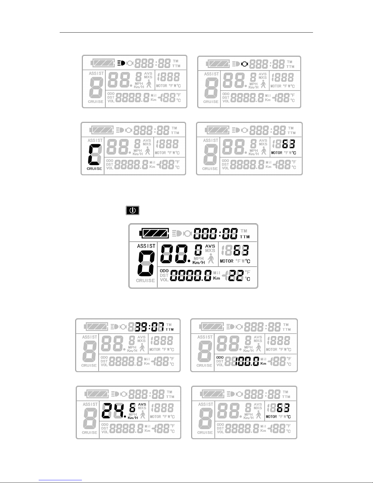
Page 12

ELECTRIC BICYCLE METER KT—LCD3 Product User Manual
- 11 -
In display 3, hold button (SW) shortly again to enter display 1.
℉℉℉℉℉℉℉℉
In each display interface, if you hold button (SW) long, the meter will be
powered-off together with that of the controller.
○
PAS Ratio (or Handlebar) Gear Switch
Under normal operation, hold button (UP) or button (DOWN) to
switch the power assist ratio (or handlebar) gear (ASSIST), changing motor output power.
Switching range is 1-5 gear (this can also be configured according to the customer
requirements), gear 1 is for the lowest power, and gear 5 is for the highest power.
At every startup, the meter will automatically restore gear (this can also be
configured as required by users) when it was at last shut down. When the power
assist ratio is gear 0 zero, there’s no power assist function.
○
Power Assistant Push Function
Users can use 6Km/H power assist function when pushing vehicles. Hold
button (DOWN), the meter assist function logo ( ) flashes, the vehicle drives at the speed
of no more than 6Km/h. Release
button (DOWN), the assist function will be
Ґ1і'іҐ1
.Ґ1і'і
Ё
ции
-ци
ттм
АЅЅІЅТ
І
І
ГЗ-3ГФ
-А
ё
Ґ1
Ґ1і'іҐ1
Ь!
&д!.!&3
МОТОК
Ш
\/0І_
дм
Ей
И
33
ЬЬ°с
]
Щ
Ё
1/
/
-ГГ
_//э*Ё\_/$<
ї"~"д`
_
_
_4 _/\
_
г`^#
Єеаг
Ѕ\УіІсІ1
Ё
~
А»
1*/›/іт
Ц
*
Ы
Ы
'Ыгапад.
Аззізт
(__
,
,,
_$__
,,Ц
1,,,
Є
*
1
`
г«
1Ґ:А
;
_/
_*
»
*»_;
_
ВҐ!ў
3
*
ЁНЁН
”\
Нщгпт
`їш'“
-
_
Н,_Щд_дЪ1
_1_1ші
*
ЦЦ%;›ЫУ»«
"И
її
її*
гд-Пї=
'дтдд
\~'
~.і
__і
_~Ш_
,мм
і_/
_/<
РАЅ
Кайо
(ог
Наш1ІеЬаг)
|‘!I'!i‘!i:§§l‘:E:gjmf'
T
il_lT
TTM
L...
E13
E3
ASSIST
B
hl;l?TF‘H
_~*)llIl
Km/H
1
‘Q9
-4
ilblli
-.1
O
r;
-J
:
FY"?!
UL!
MOTOR
‘
lLlilT1lTTllll]‘Il
Il;II_If~
~g_
‘
[ET
Il
piiU
VOL
lflr
T!-'1
l'.'."Il
O
lll‘l'
ll’
=e"a’%u!
ul
°
a
“-7.
ASSlST
|'l
I’
IlIl'
Ell
JNI
I
I
_
r151
.Ti~
II
l—
:3]
’lll
fl
°_
IlIlIljlllIlIlll
.~'~'_~I_‘I1'l~lll1+
E‘:-K7‘I1lliél"1l
‘ii?
l llIll_l
l
‘\I,|
IIIIIl
I__
I I
I/I III
I
lI‘lIIl
l lIlIll_fiIl;li|F"l]=fl
£119
Ir Ir
“
l
l
ll
a
.
I-I
I
-9-\.6‘
\I.IfW,lj,=
.>=;Il
Ilia‘
,.i’I'Il;§;Il
,.‘iII,~TI
I.\l
I\l
I
raF~l_,lll;%».Ll
lll‘ lll‘ llll
ll‘
ll“
//
ll”
lllilI
l
A
Ail/HI
lwli
\
PAS
Ratio
(or
Handlebar)
Gear
Swltch
S
lilllzil
tll
l
r
Mn
|iI'*'~._I
III,II;::;_;IIII
Ir‘Il7I‘-/lIrIl I‘IIl
I__IIIlI
,
;
"rEl,1[Til
Tjljl
I‘><l-ZIYJ
Il?<"IZI‘Tr
rj:I‘><
'
lllll
ll_-!TIII_ll_l_l_I_l
lIIl_l__Il
ll
"I~J1
l‘“‘ITIl "l
i“IEll‘iTll!lll"T
—
I
l l'l
lT,
T,
llllll~;IT<»
Ta;
._
l l l
l l l l
l
liil
F
Page 13

ELECTRIC BICYCLE METER KT—LCD3 Product User Manual
- 12 -
revoked.
○
Cruise Function
When C7 parameter setting is 1 (see C parameter setting), the meter turns on cruise
function, hold button (DOWN) long to enter the cruise status when the vehicle
speed is more than 7 km/h, and the cruise function logo (CRUISE) lights. Brake or hold
any button to revoke cruise function.
○
Startup Backlights and Headlights
Hold button (UP) long, the meter turns on the backlights as well as the vehicle
headlights (the Controller should have headlights driving and output functions), meter
backlighting and vehicle lights power logo ( ) light, hold button (UP) long again
to turn off backlights and vehicle headlights.
1ї¦
ё››о<
882
:33
дм
Аээіэт
3%:
,ОО
п
цц.иЁ;.Н,Ц:о:Кг:Ё
ёёївввв.зі±д+вв::
6Кш/Н
рошег
аззізгапї
риЅ11
Ґипсгіоп
Чї
200383
=8Б
її..
*її
'ага
~
дп
Ьа.;Ёа
ЁЁЁС
ёёїзввв.з:;+вв::
\
_
Сгиізе
Рипсііоп
ёэ
<\__II;II
IIIILI__1‘
TM
WT
TT
O0
Wym
fI_I_
\I_f
WW
C
E:
//M/M
/M
/
/My
/M
/I
//II
/_/I_
/II
/I\I_JIF®
©©
@
W
m\|[i‘_%
WWU@
IF
mwmw
SI
I
X
3III
V
.
FAM_\IIIK_II/_
I
fiJl||\/I1“?
IIII_ynI_H%_AIII\
O
&I\UY£
M
}IIIXmIIIII\y
mVI
‘II‘(NII/\&III_Z
3/>\IIII/II/L
/,Ir_|_|_|\\/I//|I_|_|\\“
~‘\\
I%¢<_\iIP/L
IWAIIZ
III
A\I[_I_|I)
II
pd//IIIIIyA/“IIII\M
7”‘
/\\
IPIFIIE
W
m
_H_
H
_
_\_\//4/\E/I_
T
IMIIIIII
I\IIIIII
@_IM_
III“
gm\A//R
M
an
WIW
pc
Hm
mm
K
t
n
a
t
S1S
H
u
6P
Q
/K
‘I’
TW
AII)
F
QIIDIIII
KIIIWXIHIFVI
IJ‘v>
&II%HIfi%
O
G
AIIJ
Tl
II§
ii
II\/III/V_
QUDIMI
>AII)IIIIv)
PI
I
UHIIWI
WV
C
:2:
//4
//MI
///
/
/
/
/
///
///
9
//
/
//’
0/
I
/I
,
AIQAJ
_IhIg
F
{L
In)
FHBI
fig
fIIVAIIII
@
II\M
*S_IIIx
Hwy{NOi“
Wk
VIII
_\/H
I/D
/IV
MMHIXU
C%£Wm
O
I)AIII/
\IIII
J
\\(
\
p
_III_\/¢III\\p
<_%III//\III€i
NIIIIIVI/II
IIK
I)“/III/¢
\I_IIIIIV
p
/pII_II>//III)
KAIIIV
/IK
fig
IéQ
4
F@
@@
W%®
M/wk
NIIAIIV
C
M
m
W“
W/Au
H
_W_
\
‘Kl
/Iyh
®“UL
O
_/AHVAIIII
}
II‘)
749$)
fip_U_
@T_L
_©_DMM
_II_w__IIIII_
T
Q
/(III\\V\/M///IIII\_\w
FL
QMpé
U
/\
R
"z-vb“
\
\
n
O
fi__
C
n
u
F
B
S
_m
P
C
E
Q
I
Page 14

ELECTRIC BICYCLE METER KT—LCD3 Product User Manual
- 13 -
○
Battery Capacity Indicator
The meter can automatically identify 24V, 36V, 48V battery capacities when it is
supporting use with the specified controller. When the battery capacity is over 70%, the
four power displays of the meter are lit, when the battery capacities drop, the four power
displays are off in order, when the power capacity is less than 15%, the four power
displays are totally turned off.
When the controller is power off due to voltage shortage, the power display frame
flashes, indicating the vehicle has been in voltage shortage and waiting for shutdown
currently.
Voltage shortage flashes
Battery capacity indicator
○
Motor Operating Power and Temperature
Under the riding status of vehicle, the real time running and output power can be
known via the meter displays.
аші
Неа(11і3І1І$
~:
*\
=;\
~д\
^:зЁмЁ*
(ЁЁ1ты
/
//1:
`~'
_:1І\Щ*(Ц
МцНЩ*тт
/і\:{з:}]і}1\/
«
Й
/Н
М.:-<
/М
,_
,_
1_
_ _
2!
її
;“
жд
_!
,_
м,_
дд
1:
~
×
Ч:
/;±7
У/_\«/
_/
_
~
МШШЕ
~“:×М
Эд;
їі
Щ
ЕЕ
:Ё
*
І
*П_
/
мышц
_`\
,_ ,_
_/
М..
“_
:
"
*
МВТС^:*::
_
Ч::
_
/`_`
д`\«`\ы\«,
\ \ 1Ю_
~
(+4
ц>-15
\Г×_1М_
Ѕїагшр
Васісіідтз
Ы
щўг\`7`ИЧ
:;:_”_`ї_
Н/ЁМ:/\Ё`
м\**
м
\ \
^\
,
И
~
7
7
Ч
\
*м
`М\
`
›
`
"
\\
_д_Г
,
7
“Й
7
И
_
` `
ЙМЮЙ
7
гїщ
Ц
г“\\<=`\`чш:*ИР1
«~\»
11
щ
»
~~
ті»
<~
\
1ил¦
фІл¦
ф«щ¦
4¦
»\¦:ІЁ
Startup
Backlights
and
Headlights
'
$
/?\~
,
\//
\\
\
r,”\j//“I
/
.
\
Pu3H
4.
(@151@if,
A
\
-1
_
‘——4
\4
r"-
K
\\‘
I
—\
¢
III17
</\
1§
W__,_
_
il=¥mQ»HQTv*7"
'
\\
//
/\_\\\i/f/»_
/\_\\‘\i/(/.\_
'
xi’
‘
\H\\]
1‘
A-J)-‘!~\\
7
III,/
~I\»»
5%/,II»T§1]
1:f3~§i
mgm~@Tn1»R
@*F
W
>
/A‘
I<‘||—|'fiI
‘I:I'
\
L
\/‘
Y
\/H
-w
U
y.
1
_/"—<
-__/Q$1
4
,-_
\*_
<‘i‘*~
I
__-
\,__y
~T_-
~»___/~
fr
=‘
‘i7l»’]T]“‘
F?
F/F1F;TM
—
aH*r¢~*‘UUQUU!I
TTM
1_f1£‘J1'f»*
\
\i,
'_x~
.
If\Ii
|
.\
\>,'~\|
(
:_'*a
Q
w
‘+5/'
‘IW‘W1W£14'J*W§;uM
[Km
W1
‘1
J1‘
“£1
A7,
““,r':‘ILI44
T\I
I
‘r,
@‘@@‘'“'
I“?
W’)
/U1
MEN
4IJffi]‘1
@F
U1!1U
~-
1;
'g;@FiL_flé;E
/
0
'.¢_\
u
II
Q~
J
‘Id,
E’
III I IIIII“-;"IiI<~/'I\1*-M7
6.13
»,~.'~*-1/
_:-I, »_~._i,»
_‘ _‘ _‘
L
!~\
/Mm
,
//
§~
TM
S
“
I,;;I—U
@’¢p;A¢'
TTM
i‘
I
'/‘III/‘1’II/‘1’I
/L?
I‘x\
I I
‘UFM)
/,1
I
‘If
-j‘]\>~
MI
‘I
.L,
I‘),V.
/
F,
__‘
‘H77.
\
<
>‘
V
finfiq
Q
i
_
-*-
‘
“.4
‘"3Q,
(Q:MWR91/‘F1
I
\
A
N.
,5!
3
*:~
.
I
§:5i;~».
,4"I‘H
/V,\W7.\__
‘
QyF\'
*1
*
L‘
H
If
NH
‘ff
MP
I»
1J/J
:,»I/IA(___>
W!
U}i§.flLQ\;Tq{i1)RFWU
‘LU
T.\_.
,»/\
w}.
, \
\
,1,
j
.41
w?*\
‘
,
IIe
/
I
"SE
"\
,9)"M|V\_HE
"\*~_._.1"""
,r1"
\u-U
I//"V
I
‘LE/|%/I
I III I
I I
I IIIII I III
I IIHIM
H H
I I III
I IITI
F
*€/i’"
I§§?.
,:~.‘X.2\~V/.
,
’
Ff?If[H]
ff’/J
Hf)‘
I)‘I]H
Bfmm
if;
H/I
IIIL
U
JLuLJ~\)‘Lx‘
K/,[H__J
K/_
Ix}
A
LR}
~
x
I
~;“"’
I‘;I
I2"/i‘:“,‘.~"I
‘I-if‘
,
/
II:/‘{L=3
\_\.
’_/ ’_/
/ /
’_/
/ /_//,.’
/1/’/_//,.
/
/‘/
'1
/‘/'1/
,1
///'1/,1/
/
//
_/
>//
_//
_/
>//’
>41
4/
/ /"/
/"/'/
/"/'/
'
, ,/.
,/.
.1
,/,.11
‘
‘.
/
H
/
/
‘.
1‘/'
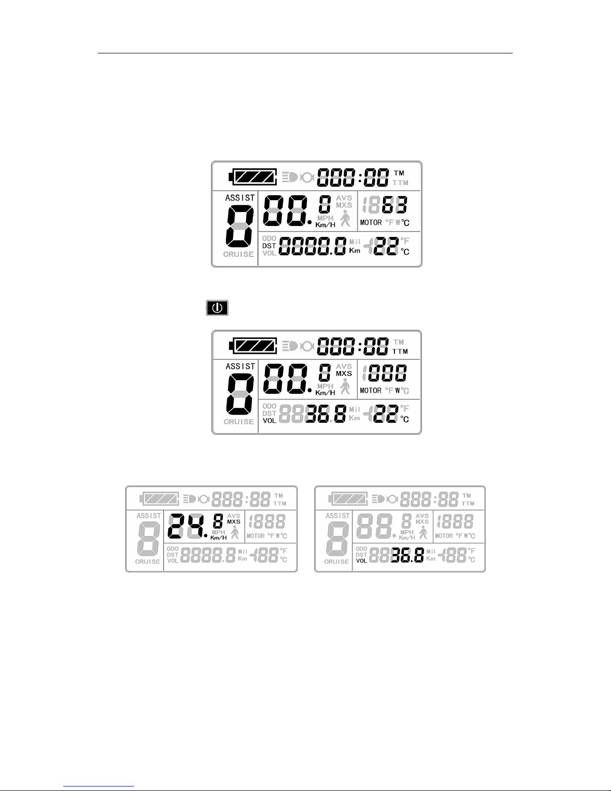
Page 15

ELECTRIC BICYCLE METER KT—LCD3 Product User Manual
- 14 -
Motor operating power
The operating temperature of the motor shows there should be a temperature
sensor installed in the Inner motor to output the temperature for signal detection
simultaneously.
Motor operating temperature
When the motor operating temperature exceeds the warning value, temperature
display flashes to alarm, meanwhile the motor controller will offer the appropriate
protection to motor.
○
Environment Temperature
After startup, the environment temperature for using meter will be displayed in
environment temperature display column.
Environment temperature display
The temperature display value may be in deviation shortly after boot-up, and the
display value will be gradually approaching the environment temperature within 10
V114:
ED0333
:33
3",,
ASSIST
f|Avs
‘mam
H
I2|“"£S
"Zulu:
'99
4.1
l‘n'
_-.1
—
KmMP/H“QMOTOR
°Fw°c
U
CRUISE
55
cu
cu
‘.33
onIon
5'1!
V114:
an0333
:33
I11,
ASSIST
'1
Avs
‘flmfl
r
£1
""£S
nininin
U
‘
0
MP“
Q
MOTOR
°FW°C
'1
Z
I’!
I
sag
-
DJ
.:‘
'3'?!
'-
UUU
‘
UUOF
G@E
v.1.u
I3":
40.0.;
:0
A
V114::00
333
:33
3",,
ASSIST
flAVS
‘mam
H
v2|""’£S
0:030
Q
‘DO
4.1
I‘u'
_-.1
|.'§',','f/'1,RMOTOR
°FW°C
’
U
ono
l
DST
CRUISE
VOL
2-:
cu
on
.33
onIv:-1|
91!
Page 16

ELECTRIC BICYCLE METER KT—LCD3 Product User Manual
- 15 -
minutes after boot-up.
○
Single Data Clearing
5 seconds after the meter is powered on, at display 1, hold both the button (UP)
and the button (DOWN) simultaneously for about 2 seconds, the single trip time
(TM) and single trip distance (DST) flicker, then hold button shortly (SW), the
record contents of both will be cleared.
Single data clearing display
Under the status of data flashing, if there were no operations on the data within 5
seconds, the meter will automatically return to display1 after 5 seconds, and the
original record content will be saved.
○
Automatically Prompt Interface
Error Code Display
When the electronic control system of the electric vehicle fails, and the meter will
automatically display (flicker) fault code. You can’t exit the fault code display only the
fault is removed.
Error Code Display
Error Code & Definition Table
[
T
if
*'IxT.
In/F;
I
I I
I7’,
I I
I7’,
I
ct:
cm
c_:I
:11
1::
VII
#
Z
II
II.~.I.IrLJ~‘
..I
I
I
\
I
I
WFAII
I
‘VI
I I
IT“*1
II
@FUUEE
II
I
I
I I
I I
1*
IIIII I
I
/If7‘I
H
"\
IiI"Ij::II'7§>.
“F
IIIII
JILL?
I
'IiI‘@J
H
I
#I‘;‘I—5;IIIII‘I III I I I
I III
I I
ITIYTI
III
Tjii"
I;~iII
|I*:ii;><:‘
II*iiiIiY<:‘
II“?}i,¥*<:‘
I I I
I III
U:/U:;I\_,_J
II;II7I:!kk‘II
IIII:“VIfI%II
IIIIIH5‘
*_IIIIIIj‘
III?
IIWIIIIFI
IL‘u->;I
I5:
_
II“
y4<I@
T
V
A
_
'
yV“‘
IQI
F
Q@J‘iF1“r1’I'lr1IflMrfiw}+
IVITIILIV?‘
I
W
//
//
I23
Ci;
\\
\\
Page 17

ELECTRIC BICYCLE METER KT—LCD3 Product User Manual
- 16 -
Error Code
Definition
01info
Throttle Abnormality
03info
Motor Hall Signal Abnormality
04info
Torque sensor Signal Abnormality
05info
Axis speed sensor Abnormality(only applied to torque sensor )
06info
Motor or controller has short circuit Abnormality
Motor operating temperature alarm
Under any interface, when the motor operating temperature exceeds the warning value,
the motor operating temperature display flashes to alarm, meanwhile, the controller will
offer the appropriate protection to motor.
User Setting Project
KT-LCD3 meter user setting project
℉
General project setting
℉
P parameter setting
℉
C parameter setting
General Project Setting
○
Maximum Trip Speed
Under power off status, hold button long (SW), the meter is turned on. Within
5 seconds after boot-up, hold button (UP) and button (DOWN)
simultaneously for about 2 seconds, the first is to enter the maximum riding speed setting
interface, then the speed display column flashes. Hold button shortly (UP) or
button (DOWN) in order to set the maximum riding speed value. The default maximum
riding speed value was 25Km/h. When the speed of the electric vehicle exceeds the set
value, the motor will be stopped driving.
Y
Em
U
Page 18

ELECTRIC BICYCLE METER KT—LCD3 Product User Manual
- 17 -
Setting interface of maximum trip speed
Under the setting maximum riding speed interface, if there’s no button operation
on the meter for more than 1 minute, and then the meter will automatically return to
display 1, and the original set values will be saved.
After finishing the maximum riding speed setting, hold button shortly (SW) to
save the current set values and enter into the next setting.
○
Wheel Diameter
After finishing the maximum riding speed setting, enter the wheel diameter setting
interface, and then the wheel diameter display column flashes. Hold button (UP) or
button (DOWN) to choose the corresponding wheel diameter specification to a
selected vehicle. The selection range of wheel diameter specifications are 13 species such
as 6,8,10,12,14,16,18,20,22,24,26,700 c and 28 inches.
Setting Interface of Wheel Diameter
Under the wheel diameter setting interface, if there’s no button operation on the
meter for more than 1 minute, and then the meter will automatically return to display
1, and the original set values will be saved.
After finishing the wheel diameter setting, hold button (SW) shortly to save the
current set specification and enter into the next setting.
'
E
‘in-I’
UUH
I
//
~/I
I
I,I_IjIII1i:I;IIIIIII,I
TTM
,\
\\
RI
(FA
I51‘:
II*II@@I@311
‘\
/
I
/I/II,»
~.
w
v
I
I
I
I
I
/
Q
L
\
.,
KL‘
‘\\.\‘
/‘
Q
MXS
Q
II
Ii)
II
I/I
0
MM?/HH
II‘IIIIIT;IT@F%
‘QF
III
”f‘
‘-3
II
/\
-_/
I
,,y~I_-I.
::I\,,.
III
I
/
,4
3:.
.
*11I.~
~_»
~:>__
I»r‘7_§
I;/I
~I—»=~I.1;
If/>.
/I
If/,,_
D
I/I
I_I§Jj‘IIy,I
IQIF
I
UH
IS‘I
II
IIIIIIiI»IIWII
ITII
ICIFQI
»I—\
.
//
\\
L
U
‘
‘I<
\\
“K
jg
I
TM
\ZIIIT*~-I)
I
TM
IIIIUIIIT
~—I~I
II—I~IIIII
~~\*AIIII
IIIIIIII_I
I
I
ITTCITIIIIIWIWII
ITII
~IQ
I
I
IIIS
I
>1II:I:I/I-§2*»>¥f”I><;
,:<<i;>;
,>;
I_:.\
:_:
4
II
“I:I"~I
'*IiF‘~I
I~\,,I
,
,II I
I\III
LII
I/LIXI
II
I
I
IIiI
HI/fliffll)II
II/I1II I
\\
IIIII/III
II/IIII
F)
/III‘
3
III
1
I
I
I
I
~:
\\,\,/
I;
;
:IIIIIIIII
:,
I
III:
‘L
II§“fi-II,III‘I%II
IIIIIQITIQIIRUFIII
TILE
/7€;lIiFI£I\\I
III//I\I
III
I'TjI‘I[IjII'@I
~'
/I
,~
(I5)
K,II I
I
,;:*:i;\
I"'‘*’IIi’
I
‘*III4I
I4I_
_
,/;<*;;
‘5l_§f>“
ID
I1:
:<:**
T
/:*I:
f
I
IIIIIJL
1:-
31'
O
Ii
<:j“*
I?‘
I11’*3‘:9
.:.
=.
':II'
/4
\,
\\ 4
.;I
H~;'
F
IDIQQT
3:5‘i»1';»I";>".1
;@:
:?:<.A
,1
I
I~II»’—I:I~’I5:I
I
II;0_ll_twII
II II IIJI;IIgI
\\
7/
L
I/‘RI.\I/°§1I
I/‘I.
/'
F»:
“K.>~.>~.»
I
I
I IIIII I
II‘
ETII
III
K
Ia
I:I
III;
IIIIIQITIDIIF-I
‘QF
III
T
I
[
1
if
II”fl|f|iY|I“rIjI
IEIII
IIIII,_IjI
Page 19

ELECTRIC BICYCLE METER KT—LCD3 Product User Manual
- 18 -
○
Metric and Imperial Units
After finishing the wheel diameter setting, enter into the metric/imperial units setting
interface, and then the speed and mileage unit flash. Hold button (UP) or
button (DOWN) shortly to make sync selection of three metric/imperial units as speed,
mileage, and the environment temperature.
Setting Interface of Metric/Imperial Units
Definition Table of Metric/Imperial Units
Display Metric Imperial
Riding speed Km/H MPH
Total distance Km Mil
Environment
temperature
temperature Fahrenheit
Under the metric/imperial units setting interface, if there’s no button operation
on the meter for more than 1 minute, and then the meter will automatically return to
display 1, and the original set units will be saved.
After finishing the metric/imperial units setting, hold button shortly (SW) to
save the current set values, and then speed and mileage units stop flashing. Hold
button (SW) shortly again, and the meter will enter into the maximum riding speed
interface again, or hold button (SW) long for about 2 seconds to exit the general
project setting environment and return to display 1.
○
Exit General Project Setting
Among the three general project settings, after each setting is completed, if hold
\\
‘L
J
1?
~\
W"
.u\n,~~‘
._.
f"‘4}‘
C
x)\‘x‘
If If
U
U
J‘
I
J
é
r
2
W
‘ZN
ZN
\
7‘
J.‘-3mi"\‘"
\
““*;‘
\W\\‘\W\\‘\W\\\’\
\
\,\
‘;V_\‘ ,\
‘ ;\V__\‘ ,\
“iii
H
W
J JJJ
_ _
\ \
‘ ‘
J
'r‘§""fi"::—‘*
‘1§"'7‘i7
ii-I
.
‘ ‘
“ “ ’“w wM,”
M‘TW‘*“WZ*‘J‘
1‘jMe
W
\‘J4'
~;'1;_:;
\ \
"3.'
\ \
,_
\ \ \
‘u
J‘;
J
"
‘
J\,__
M
QJ1
M2‘
\:\
~T~'rq"~
u
‘ ~j*\
Km
/|.|
,j
H>;¥fl*=A.<;i»\T\lwF%i
F“W~15
@[1?@i>
[IvTQ
E
._.~V,~-‘
i,~\._‘
"'1§
~\
\\ \
\
'-<'-F;\,
»
rs‘1’J
@,'»‘ »U‘1’7:M\‘11]M
ll
j
\ ?1/G’)IH\‘I‘M
/“NJ;
‘\‘VI\‘VKIT]
*J‘J}‘
‘fi"V;VfiJb£V‘/‘
DC
//
\ \ \
..\
‘
\ 1»,\,I
.
I
W
rf_‘7[j,\
O
AJ‘1’,4J»‘Qw‘F
[ I
if
[ I
if
[
T
if
[ I
if
Page 20

ELECTRIC BICYCLE METER KT—LCD3 Product User Manual
- 19 -
button (SW) long for about 2 seconds, all can exit the setting environment and return to
display 1, meanwhile, the current set parameters are saved.
Under each setting interface, if there’s no button operation on the meter for more than
1 minute, and then the meter will automatically return to display 1, and the original set
parameters will be saved.
P Parameter Setting
After finishing metric/imperial unit settings, the speed and mileage units stop flashing.
Within one minute after stopping flashing, hold button (UP) and button
(DOWN) simultaneously for about 2 seconds to enter P parameter setting environment.
○
P1 Motor Characteristic Parameter Setting Mode
P1 is motor characteristic parameter setting mode. P1 = motor gear reduction ratio×
number of rotor magnet pieces, just rounding if there’s any decimal.
After entering P parameter setting environment, the first is to set P1parameter, P1
parameter column flashes. P1 setting ranges between1-255, hold button (UP) or
button (DOWN) shortly for selection.
P1 parameter setting interface
Under P1 parameter setting interface, if there’s no button operation on the
meter for more than 1 minute, and then the meter will automatically return to display
1, and the original set parameter will be saved.
After finishing P1 parameter setting, hold button shortly to save the current set
values and enter P2 parameter setting interface.
○
P2 Wheel Speed Pulse Signal Setting Mode
/
//
\
L
‘\
\ \ \
‘x‘? ?
\ \ \
r
'
\
§
\
*2»”
-
,;_I»,7?
LlQ‘reMU‘
j
4
r*___i\
\‘_J
:1»
:T1T
\‘£‘,»zi;v(:
*7‘
inN
I
i
}
T T
_
'\'
;/‘
K
\
»
\
5?;
'
‘in-I’
QEU
mi’!
:
i
T
r—\
_
é
T T
,
jt
‘
J;
EU
U
JJ[SW
i
3
_E,/
VIII’!
__
Zggui
if
FIE
I
Page 21

ELECTRIC BICYCLE METER KT—LCD3 Product User Manual
- 20 -
Enter P2 parameter setting interface after P1 parameter setting is finished, and P2
parameter column flashes.
P2 parameter setting interface
P2 is wheel speed pulse signal setting mode. If wheel generated 1 pulse signal by a
revolution, P2 should be set as1. If wheel generated 6 pulse signals by a revolution, P2
should be set as 6. If users didn’t configure the pulse signal system, and then P2 parameter
setting can be 0. The setting range of P2 should be between 0-6, hold button (UP)
shortly or button (DOWN) for selection.
Under P2 parameter setting interface, if there’s no button operation on the meter
for more than 1 minute, and then the meter will automatically return to display 1,
and the original set parameter will be saved.
After finishing P2 parameter setting, hold button (SW) shortly to save the
current set values and enter P3 parameter setting interface.
Please Notewhen P2 parameter is set to be 0, for the built-in clutch motor, there will
be the following defects, when the internal motor rotors stop or the internal rotor speed is
lower than the outer rotor speed, then the speed displayed on the meter is inaccurate!
○
P3 Power Assist Control Mode
Enter P3 parameter setting interface after P2 parameter setting is finished, and P3
parameter column flashes.
4
fl@
TM
\
.1
i
\
\\V»»
.7
‘?
J7:
/.1»\~r.@.J
"5-P
1,=\@;~q;»
@.;~:~
,7
r\
,
\‘
I’JI1%’j’If
7
H
’A‘ff
“x
\
-FT
'f;;._
,
, \
.
._V\‘
3
JIFAZQ;
\.\\i1/,
F3
\
£§l,‘@}{Ql7
MMJ
F
Q”
Eiiirrn
”*r%;'
,'iU;
»"]U[
/
//‘‘
ELMST
%
§‘vi;j"{
LU
I
r”1*"
I
\ 1L.
_
?
‘/’
/ /
-V
'f:§:i{T
.r~z;Z?»1:
;;._,:;
‘
iii’
I/l_LIM1?”
W/41'e‘HifI“
':/
//_—_'
,_.
,_\;_,
\
\./
‘$1
<~"'
1
Ml1T@iI?*F%lFW
I I
if
‘,7.
F
_\
Page 22

ELECTRIC BICYCLE METER KT—LCD3 Product User Manual
- 21 -
P3 parameter setting interface
P3 is for power assist control mode, when P3 parameter setting is1, power assist
control mode is gear 5 of "imitation torque control" mode, when P3 parameter setting is
0, power assist control mode is gear 5 of "speed control" mode. P3 parameter needs to be
determined according to the distributed function of the controller, its setting range is 0 or 1,
hold button (UP) shortly or button (DOWN) for selection. P3 parameter
setting method is the same to that of P2.
○
P4 Handlebar Startup Mode
Enter P4 parameter setting interface after P3 parameter setting is finished, P4
parameter column flashes.
P4 parameter setting interface
P4 is handlebar startup mode. When P4 setting is 1, indicating the handlebar is under
"non-zero startup" mode, namely, the handlebar can be effective only after startup the
foot power assist. When P4 setting is 0, indicating the handlebar is under "zero startup"
mode, the motor can be startup by the handlebar directly. P4 setting range is 0 or 1, hold
button (UP) or button (DOWN) shortly for selection. P4 parameter setting
method is the same to that of P2.
○
P5 Power Monitoring Mode
‘ILV,_
Klllq
__
_
W“?
‘AI
‘M:
E
C
:
F
I
Q
firM,“min
V
h_,__
2
‘__Z_
//_W‘w_‘_
HM
5:
U
§ L?{
__
V,
fl”/pf?
//Q
A‘)
2
L
_
‘Q
HII‘,
\iH
i/FL”
3;
7}!
i
\‘|‘|H
3'.
_@_3
HM
NHL
E
Q
//,r|'\,¥‘
__‘_\,;_
F}
¥
ill
HI,7
V7
E
yr’
V/L
QXJIHMU
_\\‘,/
Rik/W
ESS
i
_
V‘
71W}‘
KKK/5
ilk?
1
Al}
(I
’\_r'§‘Jy
\_‘\
{J\ff_I
\/
__Sk_
___‘|‘|_
‘lllwt
{A1
V(J_H§{‘
K
_/V
X\‘)‘M\/
_
“ll
f
_‘____
,,,_“ny
1/
ll
I.
FWM
/‘H\
__\\\
@TL
:
L
F5
K’
U
“A:
Q
‘“_
HQ
E
Q
Page 23

ELECTRIC BICYCLE METER KT—LCD3 Product User Manual
- 22 -
Enter P5 parameter setting interface after P4 parameter setting is finished, P5
parameter column flashes.
P5 parameter setting interface
P5 is power monitoring mode, when P5 setting is 0, the power monitoring is the
"real-time voltage" mode. Namely, it is the method to determine the battery capacity
based on real-time battery voltage. When P5 equals to a specified parameter, the power
monitoring is the "smart power" mode (this parameter is determined by the battery
characteristics, ordinary 24V lithium is generally is 4-11, 36V lithium is between 5_15). P5
setting ranges from 0-40, hold button (UP) or button (DOWN) shortly for
selection. P 5 parameter setting method is the same to that of P2.
After finishing P5 parameter setting, hold button (SW) shortly to save current
set the values, and then P5 parameter column stops flashing. Hold button (SW)
shortly again, the meter re-enter P1 parameter setting interface. Or hold button (SW)
long for about 2 seconds to exit P parameter setting environment and return to the display
1.
○
Exit P Parameter Setting
Among the five P parameter settings, when each parameter setting is completed, if
held button (SW) long for about 2 seconds, all can exit the setting environment and
return to display 1, meanwhile, the current set parameters would be saved.
Under each parameter setting interface, if there’s no button operation on the meter for
more than 1 minute, and then the meter will automatically return to display 1, and the
original set parameters will be saved.
if
T *=a¢wQtT%W@WM
_
IKV,
Y‘
@@%HwT
JW,TJ
\ \
1‘\”\“»"J\‘TL'1_<
r,*
,
‘
é,
\\‘\‘
JQx‘
J‘\
1
UuE
_ 1%
J
\I“\
I‘,
C
I
\
J
‘\‘\‘
*1
"\
/a*"\
/af
\
“‘‘ ‘‘L‘\‘{J/_a‘JJ‘j_,U
U_M
Q‘-:,*“TQ:J‘Hr
?;.fv_I€~
.
_
/‘C1
Y‘
_
IifFTHY
‘1C\1,;::U
_!'|
\I'*
HW?1*’H
'\
if
B~<i_m,.-/‘H
H<L&flA<.L;\i\T\i@1~F;
+1»,
\i§L1.1
[11
@133»
[P
Féfl
V/\
\‘
fi
1‘M1]
flxw
!,L»‘1x@q\
j
.7_
V’‘DWKfy
\
l%_"i;‘Y'
‘Z!
L_;<_
Iii
|:|
|i|
_\
L
Q
|:\\
|:_\
\ \
M
1:.
‘.»~\._
'1»Y"
\k:I..
mil‘Q.‘
‘Ir\7
\[\ \ \ \ \ \ \
ikyL
721+}:_1\
*1;
*1
—
"11'\:_
\M?*T\
\‘,I\_A
n
I I
if
‘L
Page 24

ELECTRIC BICYCLE METER KT—LCD3 Product User Manual
- 23 -
C Parameter Setting
After finishing P5 parameter setting, P5 parameter column stops flashing. Within 1
minute after stopping flashing, hold button (UP) and button (DOWN) for
about 2 seconds to enter C parameter setting environment.
○
C1 Power Assist Sensor and Parameter Select Mode
Set C1 parameter first after entering C parameter setting environment, C1 parameter
column flashes.
C1 parameter setting interface
C1 is power assist sensor and parameter select mode. Its definition is shown in
following table. C1 setting ranges between 0-7, hold button (UP) or button
(DOWN) for selection.
C1 parameter definition table
C1
value
Quantum power assist sensors or similar
products
C1
value
Power assist sensors from other
manufacturers
00 5 magnet sensor 05
01 8magnet sensor 06
02 10 magnet sensor 07
03 12 magnet sensor
04
After finishing C1 parameter setting, hold button (SW) shortly to save the
current set values and enter C2 parameter setting interface.
○
C2 Motor Phase Classification Coding Mode
\\
f
‘
“*‘
JJJJ
\~_
JJJ
J
J
Tfi~1J_JJ
Pi[J“JJ~-J_“
‘,J‘J‘J‘J‘J‘J
J
J
J J
J
J
/fJJ
‘J,
J“J—JJ"J
J“J—J~"J
J“J—J"‘J
J
H
I/JVJJ
1
-_-;;§Ji-:¢_
JJJ
7§~J,7
‘ii?-_,_
,
J J JJJ J
J J
“J‘HJ‘dJU;'7k‘~l;
T;_;§J
‘J'"J“IVI‘J‘JI‘J‘J‘‘J
J
J
J
J‘;
J J
-.~\‘___‘J
J
J J
J J J
J
‘J‘J‘JJ‘J
JJJ
,J
J
(‘J
_J
V
‘J
‘J;‘‘,»»,.‘
Li/JJ‘J‘>“EJ“JJ-.JJ
11‘V/J
H
Jqc,
:_‘J
J__
‘J
J.
J
>1»,
JJ
J‘_iJ_J‘_,J
J_J_J__J
J_J_,__J
JJJJJJJZJJTJJJQIJFJJ
JJJJJ
JIQJJJ7?
‘‘JJ4
J
J1
J"
‘J
‘J
JJJJJJ@1J[1iJJJJIJ:J
J
i
J
JJJJJJJJ*J‘;JM_JJJ_
,,_,J_
7
U
"_;,ZJE*
JEJ
‘
-.
,
J
//
[
1
if
Page 25

ELECTRIC BICYCLE METER KT—LCD3 Product User Manual
- 24 -
Enter C2 parameter setting interface after C1 parameter setting is finished, C2
parameter column flashes.
C2 parameter setting interface
C2 is motor phase classification coding mode. It is served as identification parameter
of different phases of the motor when using sine wave drive and the default value is 0.
When C2 setting is 0, indicating that the used Quantum motor phase is an ordinary one.
When the setting is a certain value, indicating a particular motor phase is used. C2 setting
range is 0-7, hold button (UP) or button (DOWN) for selection.
After finishing C2 parameter setting, hold button (SW) shortly to save the
current set values and enter C3 parameter setting interface.
○
C3 Power Assist Ratio Gear Initialization Mode
Enter C3 parameter setting interface after C2 parameter setting is finished, C3
parameter column flashes.
C3 parameter setting interface
C3 is initialization mode of power assist ratio gear. The setting range is 0-6 (gear),
hold button (UP) or button (DOWN) for selection. When C3 setting is 0, the
meter is switched on, and the power assist ratio is at gear 0. When the setting is 1, the
meter is powered on and the power assist ratio is at gear 1, and so on.
T\
J!
UT
//
Vii
(T
<
fix
/:\
‘,~J\‘;‘_“‘/.‘
~M@MJ
J@wm@
,J‘‘J
‘_‘,J‘
“:‘.,JJ\‘
“J“:,_‘
J
“VJ
\
Q
O
*M_J;'\.;\_4r’
J
J.
/%\
J
JLJLJ
\
,f
‘\—J’
~J
J\
J
TJJJ
/,
‘JTT
M
5‘
J!’
Z
X
L
<~_
J;
JJTJJ"
“Q
\:}'J
J
J
J)
W%TTTCFWw@mWm@
J JJJ
J J
‘
J‘J‘J/
J JVIL
‘Til
‘F‘J’FT1‘-Jr
JMyT
T
JJJ
J J
j
7/TJI:-/'1
J<.w
Q
-.,;J
'1"
JJ_JJJ
J
TJJJTi:?J<1>§;;»
~>‘j~-‘
J~~-‘—‘»~‘
WTJH—’“;J“‘:‘
“
-
J‘-'J?JJJ~‘\J,f7J
*1:J‘.1’
/f
\ .
J
J
E
,
JJJJUJJJJJ
E
F
V1
F
43
JJWF
,\
FT‘
~%@WJ
Wflwmwwww
m-»
TM”
@fl@mW@@@
\\
‘ti;
'
E
E
TI
‘L-1'
I I
if
/_i__
*1
Z
;_fi
/i——-
<\
J.
‘
‘\‘=
J
~3~~iJ»’
I,»
-.\‘
_J
\
/
/
J J
J
EJJJTFH
‘-
F‘
U
(]JJ’J\J_~;
JJTJQJTJQJRJ“F
JJJJJ
JCJJLJE
‘J-Q
JF.>J§a
fig
JJ£J~‘J~iis@JJ‘J
J
I
JJJJJJ\
JJ
//
Wfifigmwwfifififlz
‘H
\__/*'
J
K»/7
[fw
J‘
g
(‘Jim
/‘i
/A
/g
__/‘
wk
J
J
TM
T
TM
&
%%Jwmm
JLJJJJ
J1
I
‘ivy/t
/ii
J
JJ
‘JJ/J
/C)“
JJJJJTJL
U3
E
Q
mfifiWJ@MT
.J
._
\\
4
Page 26

ELECTRIC BICYCLE METER KT—LCD3 Product User Manual
- 25 -
After finishing C3 parameter setting, hold button (SW) shortly to save the
current set values and enter C4 parameter setting interface.
○
C4 Handlebar Function Setting Mode
Enter C4 parameter setting interface after C3 parameter setting is finished, C4
parameter column flashes.
C4 parameter setting interface
C4 is handlebar function setting mode. The setting range is 0-4, hold button
(UP) or button (DOWN) for selection.
C4 parameter definition table
C4
value
Handlebar startup mode P4=0 Handlebar startup mode P4=1
0 zero startup handlebar Non-zero startup handlebar
1
Zero startup, handlebar speed limit is
6Km/h
Before power assist, the handlebar
speed limit is 6Km/h, after power
assist, handlebar is full speed.
2
Zero startup, handlebar speed limit is
specified
Non-zero startup, handlebar is
specified speed limit.
3
Zero startup, handlebar speed limit is
specified. (Power assist ratio is
effective at gear 0)
4
After finishing C4 parameter setting, hold button (SW) shortly to save the
'1‘
._,./
[
T
if
§?““1\H111MUMJ_~1
,1.
:1;/1
~::1_1:_;J~11
11v?»/‘ML\1;é/1
1:1
A/1A/1
TTM
/1%
Pi’?
1T\T.1111:;
+1
.1
11
-'1
111
1111‘
111~11
1 1
1’
4
11:1
11-1
1<_111"T111171
1 1
171
1
111.11111
11
__
,1
‘1VI‘J1JL‘nfi
‘F
‘ ‘ ‘
7+
1ST1
*1’11
11
.‘7[,»1
U11;11UL1:.:;r*;‘-‘
11 111
)1
‘11F1711i:.‘1
11
1111111
1.11_1_1
if
*
/1'
K
1__
£171
1
1
‘~P=g_;_
;;1
1
1
1
1
1
11
1
171””
1
1
1
1\
/'
1
--,:“{k
I
‘J’;_:;‘r€{:L___(‘JiiC‘
‘
1 1 1 1 1 111 1
1 111
1 1111 1
1
E1111?
1111
111111TL1j1T1l11111F’l
1Q’F1:1'1111;1;,
_
*7?
@
,—~,~
~f:T
-
HmHfI‘
J‘,
1 1 1 1
Jill‘
“ J+1:k‘
h:,1_1.__‘
‘L
I)‘
\
’
1
1 1
1
*
—_———
1711"
‘
‘U1111“
11»-1
11i}1F”%j
L1.UQE
»
11
[11~TV11
1111
‘,1
M71‘
fijfif
\ j,}_((\\ha)
C7
1L’1‘V
W!-!1“11W
W1‘1W
11%
0
Q
[ I
if
Page 27

ELECTRIC BICYCLE METER KT—LCD3 Product User Manual
- 26 -
current set values and enter C5 parameter setting interface.
○
C5 Controller Maximum Current Adjustment Mode
Enter C5 parameter setting interface after C4 parameter setting is finished, C5
parameter column flashes.
C5 parameter setting interface
C5 is controller maximum operating current adjustment mode (tiny-adjustment of
limit current value). The default value is 10, setting range is 0-10, hold button (UP)
or button (DOWN) shortly for selection.
C5 parameter definition table
C5 value Maximum current value(A)
00 Maximum current value-5
01 Maximum current value-4.5
02 Maximum current value-4
03 Maximum current value-3.5
04 Maximum current value-3
05 Maximum current value-2.5
06 Maximum current value-2
07 Maximum current value-1.5
08 Maximum current value-1
09 Maximum current value-0.5
10 Maximum current value
When C5 setting is 10, maximum current value is controller maximum operating
current value (ie, limit current value); when setting is 9, maximum current value minus
1§1:1f11
11115111111
T1111
1
TT111fl
11111..
1:1
\11-1
L1‘
‘-i~"»;111”3;1‘
T311
1
11-1
/1_\1'1
1
1\.4
‘A‘;':’
,__
1 1
1 1
1,1
"1,
_.1
"1,
1;
__C‘H
~;__.‘1'1T_I
111111
11111
§;:11j1,_:ii
A
I
11
1111
11
111111111“
1111111—11111—11111
.11
11
1-1;»!
1
1
11111111
1
.
;1
i,
1"
111111
1
LUUE
11111
111
1
‘"1
1111111111!
11
110
L0
1 1
‘~
11:?
1.1.»
‘~.>~'Ii;
1
'
"1"1
111L111'=»
11111—1‘1‘11
11‘111_1
,
1
1 1
1 1
1111
E11
Q11
111.1
1*d1
1
1*‘11111111111/H
111111t1;11T1:1;1:11111
11F
1
1
11
1
F
1>11171:1711‘/<11
1‘_:71iV
11111111
1 1
1
*
1='Lii=~*‘:::~1
~1
1
Page 28

ELECTRIC BICYCLE METER KT—LCD3 Product User Manual
- 27 -
0.5A, when setting is 8, maximum current value minus 1A and so on.
After finishing C5 parameter setting, hold button (SW) shortly to save the
current set values and enter C6 parameter setting interface.
○
C6 Backlight Brightness Adjustment Mode
Enter C6 parameter setting interface after C5 parameter setting is finished, C6
parameter column flashes.
C6 parameter setting interface
C6 is the meter backlight brightness adjustment mode. The default value is 3, and
setting range is 1-5, hold button (UP) or button (DOWN) shortly for
selection.
C6 parameter definition table
C6 value Backlight brightness
1 Dimmest
2 Darker
3 Standard
4 Brighter
5 Brightest
After finishing C6 parameter setting, hold button (SW) shortly to save the
current set values and enter C7 parameter setting interface.
○
C7 Cruise Function Setting Mode
Enter C7 parameter setting interface after C6 parameter setting is finished, C7
parameter column flashes.
[
T
if
1
L
1,1
1 1
i11fi711‘~
111g'T11':::'1111111*11
11111111
111111111 1
1'111111111 1
1
11;;
11;;
1
11111
11111
111,11:
1t11;1:1;;<1
).:1:j1.;fQ1i111;;1:11:1
1
Z111)/’
‘=li:_/11-1114115121111111111111._1
1
117T117111:”
'
1
~/'
“#1
11:.
"1‘1
1 1
1
11i1"»;1<1
11;‘
g
@1111i11'H1111“1Y11'111111
11 11
11,,1_1,11111:1
_
111 1 1
11
1111
11'
11
111111*1’11"11
1111111111
1
1
1
1
1 1
1
11-
1
1
11"”
11M
H111M11
4.1111.11
1 11,_1
~111__;11
1
1
,
1,1_
11
11
1,_.r
1.
"
1;!11121111111111111
111
1
U
1
:11‘1'
11 117111
115
J;
1/
1111/1
R1Q~1iF%1
:11
1W171“
1W?
1
1
@@@1iIF‘IF‘€?
II
1ij*11
1Ȣ_@@_@@
1111
11111
1111111
1111111195111111111111111111
1;
QE
fl%m:agJ!-,@§;1..;
//
[ I
if
1
1
1
1F
1
Page 29

ELECTRIC BICYCLE METER KT—LCD3 Product User Manual
- 28 -
C7 parameter setting interface
C7 is cruise function setting mode. The setting range is 0 or 1, hold button (UP)
or button (DOWN) shortly for selection.
C7 parameter definition table
C7 value Cruise function
0 Off
1 On
After finishing C7 parameter setting, hold button (SW) shortly to save the
current set values and enter C8 parameter setting interface.
○
C8 Motor Operating Temperature Display Mode
Enter C8 parameter setting interface after C7 parameter setting is finished, C8
parameter column flashes.
C8 parameter setting interface
C8 is motor operating temperature display mode. The setting range is 0 or 1, hold
button (UP) or button (DOWN) shortly for selection.
C8 parameter definition table
C8 value Motor operating temperature
E?
RTR
R"RL:§1f11:R1
(FL
,1’
:
»;TR;<-
‘RK
‘ ‘
RRZ,
R’RR‘RR‘RR‘
K
.,K,
/
‘/'
”
,RR/ii‘:-.KX
F‘R"
‘R
//
if
RZRRY/»'
R‘\»§‘.*;::_I':R”
RRL/R'*R‘iVRRCRRi
‘R‘RiRfRiR5/RR‘
T
J1’
J
R
RRRR
R,R_R\_R
C
'
’’‘'I
RRRFH
E§~1R_f
R
RR
RR
RRRR
““”RRR:;
R
R)j,R'\
R
./
R
RR/15R,
RMRT
F
‘
"
1:g,.R‘
\\;L"i
R’,/'LaRf
R3,
\__.:_j
R_
R
R
HR
RR
A
\\
_:R,
,s__ilTfrR.RxR4‘
“R
TM
R'r—\‘_Ry'[‘__:‘_RRRRRR“Réy
R RRRRRRR
Rl}IRl}
R
TM/,:L.LRR.,LR,
R
Q
giviR‘R
RVR‘_R’\RR¢:R‘_J\dR
RLR,R‘_R\yR
,
RR‘-?.%ZfRR
RERF
U
R
J
RnL;\_
‘LR’RRmRRRRRRR
0
\\
[
T
if
El
<7;
R
RRRWR
RMTRRR
TM
//
\iF‘\.
»:iT:\
’I‘
‘ii
L//_,R\3;;t;;',,RR
\
C1
RRJ
‘Rf
RRMRR
T
~‘R
. ,R, .
/R‘
RRR
’iR
R,»/
\
H
R",
;1R“‘;:V~‘R
R/'~kvv~“?R~tR/:5/‘RRRRRR
R’RIIIR““R‘
F‘\"/1|)’;
"Vi
R'c'V“R';1‘R
R'/Q*R"'“‘
R"\1
,;R—~;-'‘R
R
R1?“WT\
,R.
Tm
,2
DR
_VR,
RR
\.
‘/R}
‘Jr
I
J
\R,_,_
R
7
H
RN!
{Er
.
Li;
R"
RRRR’;
/y,.__R‘RRRy
A1‘
‘R
RR‘RR RRRRRRR
R
W
\I}
(‘R_/ii:
\,;;!
Hit
R‘
'f;>H
\‘~__RJ
TR‘EQ
Lg]
F
/
-R
RRR
R
R
\\
'
‘TR‘Ra’'»1'
,._.‘J
R1,,
RR
RRR R
,6
RRRiR:R'LR
RRRRR_,4QRR
RRé;R:R;iR
‘R
F
//
Page 30

ELECTRIC BICYCLE METER KT—LCD3 Product User Manual
- 29 -
0 Function off
1 Function on
Please NoteThe motor operating temperature display requires installing temperature
sensor in the motor, output temperature detection signal simultaneously.
After finishing C8 parameter setting, hold button (SW) shortly to save the
current set values and enter C9 parameter setting interface.
○
C9 Startup Password Setting Mode
Enter C9 parameter setting interface after C8 parameter setting is finished, C9
parameter column flashes.
C9 parameter setting interface
C9 is meter power-on password setting mode. The default value is 0, hold
button (UP) or button (DOWN) shortly for selection.
C9 parameter definition table
C9 value Startup password setting
0 Function off
1 Function on
When C9 setting is 1, hold button (SW) shortly, indicating that the password
function is startup, and then enter the password settings interface, three password setting
columns flash.
//
[
T
if
L
RR
ii
R)/,
*Rir~:rR
R:?~??R1wm
RCRRRR_RRRRR_RRR,RR_RRRRR_
W€;¥K%R%;RF'i”WRw
TTRR
R
R
R
R,R
RR
RR
R
A
R
RRRLRR
R,
R
R
R
R
RR
:7
RR
RR R
R
R,RRRLR
R
.__R
R
R
R
R
R
RR RR
R
R
‘
R"R“RFRFQ
RRR*~R*~
R R
R*R~R
=1R4R*R
.~RRR<
R RRR
R R
R_R_RRR_R_R
R_R_RR_R
R
‘ ‘RRf“
R R R RRRR,’/Rf‘!-.__RR
Rf_LR__RR‘
R__R,‘
‘L,
,
RRRMEH
RRR
M@T@F‘%§WR@
R
,7,/R7R‘:;:R‘V'RI,
/.
R R
R
1;
;2=‘
RRRQRUTRRRRRRRR
H
RRRL
R
[R[R§§RT
RR,
._TRjRV,;;RRR
RTE
R
R
_R.QR‘F
R1‘RR‘
RR],-
iIWQ:@fi:WIfH
H:HRRM
_RR
1*A
RR
’*RR
R R
R*RRRHRRKRRR
B"5§TUU‘U
‘7RR
RRKR
RR»RRRR
U
RR_R.R‘L
R‘
R
R
//
R
T1
R_._J
U
[ I
if
Page 31

ELECTRIC BICYCLE METER KT—LCD3 Product User Manual
- 30 -
Password Setting Interface
The password setting is done sequentially from left to right, hold button shortly
to confirm after each setting and enter next setting. Password setting range is 000-999, hold
button (UP) or button (DOWN) shortly for selection.
Please noteIf you forget your password, the parameters can only be copied (see
parameter copy) by data source meter prier to be decoded.
After finishing C9 parameter setting, hold button (SW) shortly to save the
current set values and enter C10 parameter setting interface.
○
C10 Automatically Restore Default Setting Mode
Enter C10 parameter setting interface after C9 parameter setting is finished, C10
parameter column flashes.
C10 parameter setting interface
C10 is automatic restore default settings mode. The default is n, and the setting can be
n, or y, hold button (UP) or button (DOWN) shortly for selection.
C10 parameter definition table
C10 value Restore default setting
n Function off
y Function on
>
RR
—
R,RrR,k,
.
.J\:>
\L~
».;_
R”
~~,\_~.,_,,:
~1R"-R
RR“
RR
RR“R1}P‘ERRRIRR4
4;?/RRRR
Rf,’RRRlR‘:\‘s
‘RLR’
1;?
R
..47¥R~'R(Y-Y-R7R<):\;I
RRR
R R
RRR.
R/
'
IVR.\
R
.41
_;
‘ARR R
R
RRRARRRPRRR
RR
R
R
PR
GQRR
‘R
\
A
5/
;¢RR~@R
:1~"@*R@m;mu1RwRmm1RRRM
195255235!‘
RR
IJ Li L‘
RRTREIRTRRIR
F
RRRRR
x-\
R,"
R»‘RRa|RjR"
RR».
9;-
R-
RR
‘KR
2*
HST
1:
R
RR§i,,,
-,R
k»/3_
RiRR
R
R
"PR
‘RR“":R'
R+?R71>R
R1
57‘
R
§'R’”
l'RR,RI:RR_!R7l
RR_‘;R§RRQ_RR
RR
RR
RR:RRR,R
‘F
nR
RRRR0.RR—RRR
RRRexR
//
\\
1?
E
‘in-I
[
T
if
ll
\\
ASSRST
§==a
j
R
RRR
R
R
RRR4R
R RRR
R
RR
:,>‘\
Rx
,;/R
R R
RRRR
R R
R_
R RRR"‘:"IR‘_R}‘;R'
'i‘:\R-"R
RRYR
’€F*i?%—*H
¥#R%%
R
R
E'“"‘
RRRME7
RRR
T'?'€
R
R
R
ix
//
,.R>~RERR“-RRR
RRRRRRfiRRRRRRRR_RRRRR
RRR,Rfi_
Rh;
M@TwR
RFR
"R
R
~*@R%w@1
RWRRHRflREH
R
RRWR7
Ii?
'i""R
‘t1:R5'**¢::
tr’
RRRRRRmRRf,RR_R
“é
LE5-,3
T
RR-RR
T
RRRR
r:
_
RJRRJR;
L
QR
RLR
/--:\_RR» .
K
“
“RR
_
R
R
T
RR
RR
;§%
,__
__
:0
W
R
“RURMRfRW@R1fl@F
BRR;R‘R‘RRR
Rf,RLRRRA\R
Rf‘,,R_RR3RR
R5
QT
,3
//
\\\
'
4
Page 32

ELECTRIC BICYCLE METER KT—LCD3 Product User Manual
- 31 -
When the meter is needed to restore default setting, C10 selects y, hold button
long for about 2 seconds, all parameters restore default settings and exit setting
environment, and then return to the display1.
C10 selects n, hold button (SW) shortly to save the current set values and enter
C11 parameter setting interface.
○
C11 Attribute Selection Mode
Enter C11 parameter setting interface after C10 parameter setting is finished, C11
parameter column flashes.
C11 parameter setting interface
C11 is meter attribute selection mode. The setting range is 0-2, hold button
(UP) or button (DOWN) shortly for selection.
C11 parameter definition table
C11
value
Meter Attribute
0
Meter uses LCD3 new version of communication protocol, it is compatible
LCD1 and LCD2.
1
Meter uses LCD1 and LCD2 old version communication protocol, it is not
compatible LCD3.
2
As data source for copying parameters, the meter transfers the new LD3
parameter to other meters.
C11 selects 2, hold (SW) long for about 2 seconds to exit the setting
environment, and then the meter is served as data source for copying parameter (see
[
T
if
L
ill‘
JW‘V
*““
“*IsJJ1J J
J J
1 I1.~
\
M
(‘Q3
U-*1?‘REF,~‘
s'¢:\“~".fLi'!
~"._fJ~1'
U-31‘(V_
|‘
“\,
\
K
\¢F
\‘r’‘1%F
‘
\
F
\
E!
//
"
*
SH
AW‘H1‘MrJAJ‘.
\ \
‘
V)‘ii‘l.;‘_;:'.‘i+-.“
,f1.;lv_:']‘;;‘
_‘;3":_‘i',§f
‘jI»;;:[:§,l:_
,",,i{_‘y:?‘.%,';
in
\),,',_.;i:/~_~-‘kLiJl[:k:kyJ\
Lv}‘_“;‘\
a_\
T
‘K
“
.?\
ci\“'7*»§'~‘
,
‘N
_
7
»\\~
r'\“i‘\‘\i"\
»’
M11
l]I5Ij¢um~L%A»:é;,i
J
<7.
Hm
[0
\/":'\
,:::\1xiF,1?-\
‘A
‘F
W
[,=‘”/
-...‘
q’J»
/
‘
I1]
\
/’A1
R
/?ijr:I
./A
M
V,
P7I\
w-T
Jjiw
55‘
rm
/1:i%»‘
‘F
K‘\‘::§,>|,“?rD
[MT‘LH
7J,"1‘ff
Dim]
41/
LLJ»
U
L,_
‘Q
[
T
if
[ I
if
Page 33

ELECTRIC BICYCLE METER KT—LCD3 Product User Manual
- 32 -
parameter copy), there’s source logo on display interface.
Data Source Display Interface
After finishing C11 parameter setting, hold button (SW) shortly to save the
current set values and enter C12 parameter setting interface.
○
C12 Controller Minimum Voltage Adjustment Mode
Enter C12 parameter setting interface after C11 parameter setting is finished, C12
parameter column flashes.
C12 parameter setting interface
C12 is controller minimum operating voltage adjustment mode (tiny adjustment of
voltage shortage). The default value is 4, and the setting range is 0-7, hold button
(UP) or button (DOWN) shortly for selection.
C12 parameter definition table
C12 value
Minimum Voltage(V)
24V Controller 36VController 48VController
0 Default value-2V Default value-2V Default value-2V
1 Default value-1.5V
Default
value-1.5V
Default
value-1.5V
'
S
‘in-I
WT§j§mwWWWMWWW
"““
@
E@KMQ@Wm
1
r1
.—\
<—\
—\
L
N;“x
5
-.
,1
'f\\\
I-r:~_
LQQJ
Q~_
/~',~_
/~:~
H
;"
r’
J
77")/A
~'“
I"/11'7?“/11'W’!
.\"1‘T‘”l
/
\~.
,,wz
\,‘AA
r
1*:
»‘
‘
"
I‘»
/
/
,
\
<32»
[;;3“\,‘_§§
M£QI\T*l£DF%l
‘QFW\iF:_§
w*
(q
(
f
4
>‘
@€T
GRUUSE
‘WW:
;\'V/[P44
K?
I
5*»/AT\/17
(5
0
rs',~:./u~:.
/u
-V
F3
‘
”
-H
/’\
m@H
/~
_ _
W
W
lJ~'
Z
<11:
.»;*'\><\:\
(_w
@!fi
n»7‘:1h
':fl‘
Z
.;|
f<_
.1
.:.u
4
‘
I
*C\
\\ 0
|:»
*4
4
_”
H
@W?fiWfi@F
‘=;-‘T‘~:/
=~;»?~.;,’
/~\
6/“.
_
L
[
T
if
IGFPQQJ
U
H4/‘ii
L/_.'
,..-\‘i.v\l_V_,,,
%%@H%T
,@~+>/Kfif“
Iii
@¥€
wfiwvmiwifi
‘f
/J‘LLV,~<>‘~|,>\|
my/flL,>?i<\_§f;Q
fa]
‘x
<
\
\
J
[J
\jI\,/J‘/
"
\\
‘.11
“if
’
,7!»
*1
.7‘.
.»—‘.
f
‘
;
-.1
[V/,4‘,},
,H
\
K;
>1
\ \ \[\
’
/
\
\ \ \
/~.
//\
/
/
/»
/J
k
\_,/"'
‘\1:;;,_,
EN
If
V,..
‘W
U.
E?
F-:”u@
i*?I
L;$i
EF1
_I
‘Tm@
fi
»WQIM;uu;mm;fl@41TM
/
fji"*"Q"
‘ivO-]**"F*
// \\
s?
,
._
,4
A_\
Q
1&guLJ@w@‘w@4mgQ%@
\\ //
/
LJ
X
I
@
%,J~
LA]fi
MPH
mm
f¢@?@
mfi
1<%iV»\f ghiXAJGQW/H
gflg
M@TwR*W?W55
J
E?
1f‘
1*?
r1@»
mm¥w?%@F
L
E
ii
Page 34

ELECTRIC BICYCLE METER KT—LCD3 Product User Manual
- 33 -
2 Default value-1V Default value-1V Default value-1V
3 Default value-0.5V
Default
value-0.5V
Default
value-0.5V
4
Default value 20V
Default value
30V
Default value
40V
5 Default value+0.5V
Default
value+0.5V
Default
value+0.5V
6 Default value+1V Default value+1V Default value+1V
7 Default value+1.5V
Default
value+1.5V
Default
value+1.5V
C12 default value is 4, namely, controller minimum operating voltage (voltage
shortage value); when setting is 5, the default value plus 0.5V, when setting is 4, the
default value minus 0.5Vand so on.
After finishing C12 parameter setting, hold button (SW) shortly to save current
set values and enter C1 parameter setting interface again. Or hold button (SW) long
for about 2 seconds to exit C parameter setting environment and return to the display 1.
○
Exit C Parameter Setting
Among the twelve C parameter settings, when each parameter setting is completed, if
held button (SW) long for about 2 seconds, all can exit the setting environment and
return to display 1, meanwhile, the current set parameters would be saved.
Under each parameter setting interface, if there’s no button operation on the meter for
more than 1 minute, and then the meter will automatically return to display 1, and the
original set parameters will be saved.
Parameter Copy
Set parameters (include general project parameter, P parameter and C parameter) of
all KT-LCD3 meter produced by our company according to requirements, and set the meter
to be a data source according to the method of "C11meter attribute selection mode".
Page 35

ELECTRIC BICYCLE METER KT—LCD3 Product User Manual
- 34 -
Use special wiring cables to properly wire to LCD3 meter needs to be copied
according to the diagram.
Meter parameter copy wiring diagram
Special wiring cable
Turn on meter power supply of data source. Power supply of 48V or 36V or 24V is
available (VB + positive power supply). After wiring the meter needs to be copied, hold
button long till meter is startup. Within 5 seconds after startup, hold button
(UP) and button (DOWN) simultaneously for about 2 seconds, meter parameter
copy is completed. If the copy operation is correct, the meter subject to be copied will
display as follow.
w
Wm
EH
Um
Mf_
UQ‘NA
fig
“D
0
3
Um
%%
HM“
UH
mmflmuuw
Em%WmWUm
3
HM“
WM
ti
HM“
mm
"HQ
3
S
‘W
Ha‘
H
anan
UmUm
5NDII
DD
an
HHHA
“MU
HRH
mm”
fig
E
Q
w
EDDDUUE
%%%%fi
HE
E
flE%fifi
W
L?f
Q
/_
__
EEE
i%%Efl
E
_
Hm
I
fig
ééfiéé
ifi%;fl
_flfiflfifl:
+
mu
L’
_
mu
‘V
gm
%
J
é
Him
my
fiufiéé
g%%fifi
Aw
\N\A_A/
WWW
W
__
______
@@@
E
fi%g§g
)
fit
Hm
Hm
--
.1
E
E
Page 36

ELECTRIC BICYCLE METER KT—LCD3 Product User Manual
- 35 -
Interface of finishing parameter copy
Please note:
Both C9 power-on password and C11 meter attributes can’t be copied.
Besides, LCD3 meter can only copy parameter of the same meter model.
User Setting Note
After entering the user setting environment, if there’s no button operation on the data
for more than 1 minute, the meter will automatically return to display1, and the new set
parameters won’t be saved.
The factory parameter set value and the default value of the meter can be set
according to user requirements, the meter parameter can be restored by using "C10
automatically restore factory setting mode" approach when adjusting it.
Version Information
KT_LCD3_V1.0
Released on September 18, 2013
/
mi
\_/
3F3
f?
/?
K
H
I
r
M
»‘IW111HI
»
F’‘JU
U
u@»m@>R
@F
W
/\¢é
qi.
\/.
//‘‘\i<
Z
"2;
’
\_+,,~
7 I,
\__,,\
’
l/L]
/JTA*
>‘
\
\_»,
,»
‘E
‘z
\~—~/
\
1'
\
_\_
/fi_“
»
@‘i€§T
"i
\__
__W’T‘Vl:\]
USE\~@'”‘@L-
1.,
//
i
Sm
1
I§7TT‘
r‘W*W1r‘W
TM
E
T
‘V
E—"”
@—]
L"M~M£Fg@4M1&
¢1Q@l]TTM
¢’*\
‘~__Q_‘/\¢J
Q
V
shT)—-._
~»,
M
1 6
/1.
ik»
E
Q13
fin?
w
Q~T
/\
4/
L
f
C»
/,’_\
1,1
5‘
=@
\_
\
'\
I,
i
‘%”D‘@P)_
L]nufl)
'/
W‘
A/£3“
»_/
x
@
l':l_/I
F
\
*lL
li]Km>TMAWJU@@
 Loading...