

ICT ICT200DF-12IRC, ICT200DB-12IRC Instruction Manual
Innovative Circuit
Technology Ltd.
Dual Bus Distribution Panel
Series
INSTRUCTION MANUAL
855-314-000
Models:
ICT200DF-12IRC
ICT200DB-12IRC

2 Innovative Circuit Technology Ltd.
WARNING
Risk of serious personal injury or damage to equipment and property! Always
observe the following:
Use an appropriately rated over-current protection device in line with the
main battery connections to the panel
Use an appropriately rated disconnect switch or circuit breaker in line with
the dc inputs to enable installation and service of the panel with the dc
source disconnected
Shut off or disconnect all dc power sources before connecting or
disconnecting wiring
Use wire and connectors rated for the maximum load current and size of
fuse or circuit breaker, and keep cable lengths as short as practical
Carefully observe wiring polarity when making input and output connections
Securely tighten all connections
Do not attempt to service any internal parts. Refer all product service to an
authorized ICT Ltd. service facility
CAUTION
Risk of personal injury or damage to equipment! Always observe the following:
Install unit in a restricted access location (such as an equipment rack) to limit
unintentional contact with terminals and wiring
Ensure the total power consumption of the loads does not exceed the 100A
(pk) rated capacity of each power bus
Ensure load current through each output channel does not exceed 15A on
48Vdc systems, or 25A on 24V and 12Vdc systems
Do not block air inlet or outlet openings in the panel sides

Innovative Circuit Technology Ltd. 3
Contents
PRODUCT DESCRIPTION ....................................................................... 4
INSTALLATION ..................................................................................... 5
OPERATION ......................................................................................... 8
LCD Display ............................................................................................. 9
Status Indicators and Alarms ................................................................ 11
TCP/IP WEB BASED UTILITY ................................................................ 12
Status and Control ................................................................................ 14
Device Setup ......................................................................................... 15
Bus Setup .............................................................................................. 17
Output Setup ........................................................................................ 18
Network setup ...................................................................................... 19
E-mail Setup .......................................................................................... 21
Alarm setup .......................................................................................... 23
User Setup ............................................................................................ 23
Maintenance ......................................................................................... 24
MOBILE WEB APP............................................................................... 25
PASSWORD RESET .............................................................................. 25
ROUTER CONFIGURATION .................................................................. 26
TEXT MESSAGE ALARM NOTIFICATIONS .............................................. 28
TROUBLESHOOTING ........................................................................... 28
PRODUCT SPECIFICATIONS ................................................................. 30
LIMITED WARRANTY .......................................................................... 32

4 Innovative Circuit Technology Ltd.
PRODUCT DESCRIPTION
The ICT Dual Bus Distribution Panel provides two 100A (pk) bus inputs with six
independently controlled and monitored output channels per bus in a compact
1U high chassis for 19 inch rack mounting. Over current protection for each
output is available on the front panel in two configurations; with 80VDC rated
blade style fuses, or with 65VDC user replaceable magnetic-hydraulic circuit
breakers.
Each bus can accommodate a supply voltage from 10VDC to 60VDC, either
positive or negative polarity, with a peak input current of 100A to be distributed
at 25A maximum (15A for 48V systems) on each of the 6 output channels. Each
channel has independent current sensing, over current protection, alarms, and
output on/off control.
Remote monitoring and control is available through the integrated security
protected Ethernet communications port on the back of the panel. The unit has a
built-in web server with an embedded web-based graphical user interface (GUI)
that can be accessed using any standard commercial web browser, such as
Internet Explorer or Google Chrome. The web server displays all panel
information, allows full access to channel configuration settings, provides
remote channel on/off control, and can be set up to send an alarm to userdefined email accounts in the event a fault occurs. The web server can also be
used to configure and down load a data log of up to 30 days of time stamped
event information. Full monitoring and control is also available using an SNMP
(v2) based management system for larger installations.
System voltage, system current, output channel current, fuse status, and alarm
input status can also be monitored onsite through the front panel LCD display.
Fuse status is displayed by an LED indicator located over each fuse, while breaker
trip status is indicated locally by the rocker handle position and front bus alarm
LED’s. Form-C alarm output contacts (C/NO/NC) are provided on the back panel
for each bus to indicate all distribution panel alarms, while 5 additional alarm
inputs can be used to monitor other dry-contact site sensors such as
door/window opening, smoke alarms, and water detectors etc.
Model Numbers: (covered in this manual)
ICT200DF-12IRC Intelligent Dual 100A Bus Fuse Distribution Panel for +/-12, 24
or 48VDC Systems
ICT200DB-12IRC Intelligent Dual 100A Bus Breaker Distribution Panel for +/-12,
24 or 48VDC Systems
Other Models Available:
ICT200DF-12 Standard Dual 100A Bus Fuse Distribution Panel for +/- 12, 24
or 48VDC
Innovative Circuit Technology Ltd. 5
ICT200DB-12 Standard Dual 100A Bus Breaker Distribution Panel for +/-12,
24 or 48VDC
INSTALLATION
Inspect your distribution panel to ensure it was not damaged in shipping, and has
all accessories:
4 black plastic boots to insulate main dc power connections (shipped
with unit)
4 M8 size nut/washer/split-washer sets for high current bus connector
studs (shipped on unit)
2 three pin alarm output connector plugs (shipped on unit)
1 ten pin site monitor alarm input connector plug (shipped on unit)
Instruction Manual
8 ICT-BLP Breaker blanking plugs (included with ICT200DB models only)
for installation in un-used breaker locations
To complete the installation you will also need appropriate fuses (FKS-ATO type)
or circuit breakers (available from ICT) for each distribution channel you plan to
use. Twelve 15A 80VDC FKS-ATO blade fuses are shipped with each ICT200DF12IRC panel, while circuit breakers need to be ordered separately per the
following list for use on the ICT200DB-12IRC panel:
Breakers:
ICT Model
Rating (65VDC)
Mfg. Part Number
ICT-CB5
5A
CBI Electric BDG1ED-BOLXBS-0500X-1
ICT-CB15
15A
CBI Electric BDG1ED-BOLXBS-1500X-1
ICT-CB25
25A
CBI Electric BDG1ED-BOLXBS-2500X-1
Carling “M” series rocker handle circuit breakers with 0.25” tab terminals and
current ratings up to 25A may also be used, consult ICT for suitable part
numbers.
Fuses:
ICT Model
Rating (80V)
Mfg. Part Number
ICT- 80VF15
15A
Little Fuse FKS-ATO fuse 166.7000.5156
For 12V and 24V systems standard 32VDC ATO style blade fuses may be used,
with current ratings up to 25A. These fuses are widely available from multiple
manufacturers.
CAUTION
Risk of personal injury or damage to equipment! Always observe the following:
Install unit in a restricted access location (such as an equipment rack) to limit
unintentional contact with terminals and wiring
6 Innovative Circuit Technology Ltd.
Ensure the total power consumption of the loads does not exceed the 80A
(continuous) rated capacity of each power bus
Channel output breakers or fuses must not exceed 25A max rating for
12/24VDC systems, 15A max for nominal 48VDC systems
Install only 80VDC rated fuses, 15 A max each for nominal 48Vdc systems
Install only 65VDC rated breakers, 15 A max each for nominal 48Vdc systems
Do not block air inlet or outlet openings in the panel sides
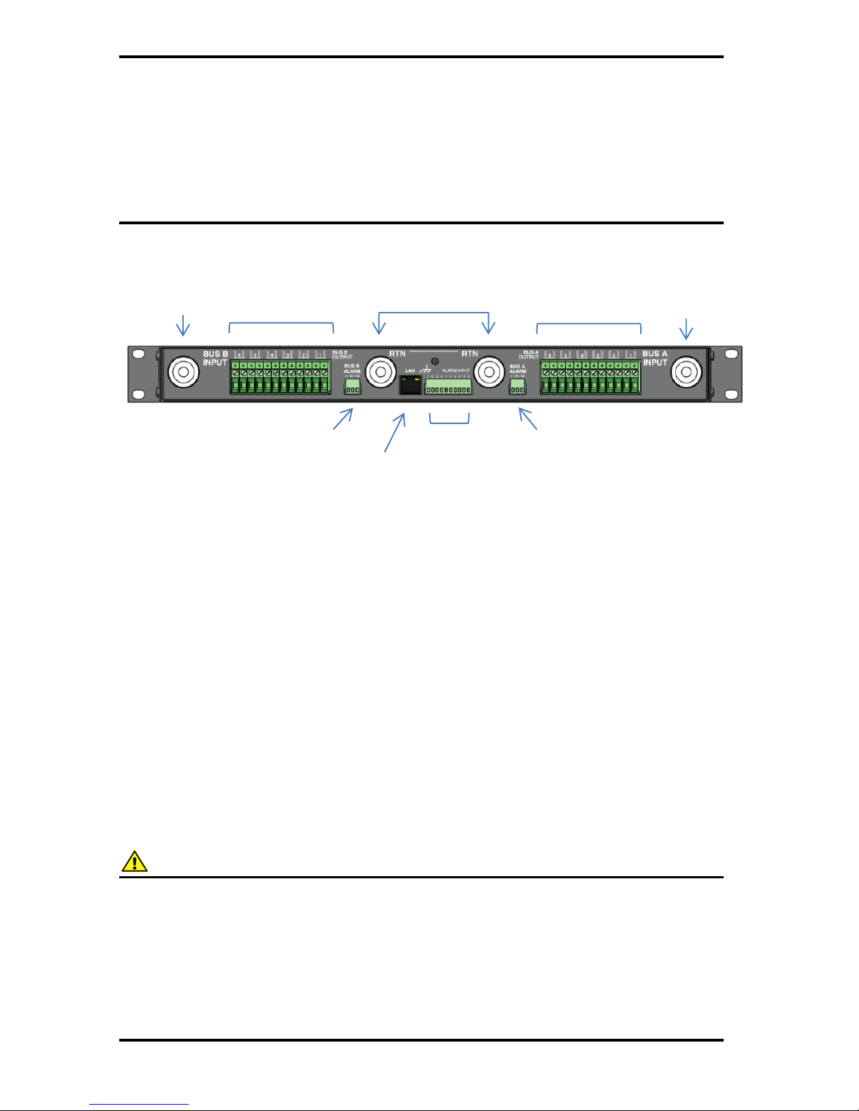
Figure 1: Back Panel Connections
Mount the Dual Bus Distribution Panel in a 19 inch equipment rack, using
standard rack mounting hardware. (Not provided)
On breaker equipped models install appropriately rated circuit breakers in
desired channel locations by carefully inserting a breaker so that its mounting
tabs securely snap into the front panel. Install the breaker blanking plugs in any
unused locations. Breakers and plugs may be removed by using two small
screwdrivers or similar tools to press in the top and bottom mounting tabs
through the cover openings and gently prying out of the panel.
On fuse equipped units change any channel fuses requiring different current
ratings. (Up to 25A max on 12 or 24V systems, 15A max on 48V systems)
WARNING
Risk of serious personal injury or damage to equipment and property! Always
observe the following:
Use an appropriately rated over-current protection device in line with the
main battery connections to the panel
Use an appropriately rated disconnect switch or circuit breaker in line with
the dc inputs to enable installation and service of the panel with the dc
source disconnected
Bus A Outputs
Channel 1-6
Bus B Outputs
Channel 1-6
Bus A/B Input RTN
Connectors (common)
Bus B Input
(100A max)
Bus A Input
(100A max)
Site Alarm
inputs 1-5
Bus A Alarm
out
C/NC/NO
Bus B Alarm
out
C/NC/NO
LAN Port
10/100 Base-T

Innovative Circuit Technology Ltd. 7
Shut off or disconnect all dc power sources before connecting or
disconnecting wiring
Use wire and connectors rated for the maximum load current and size of
fuse or circuit breaker, and keep cable lengths as short as practical
Carefully observe wiring polarity when making input and output connections
Securely tighten all connections
Bond the panel chassis to the rack system ground, connecting a ground wire with
ring tongue to the back panel ground stud. (8-32 thread)
Connect Bus A loads to each output channel using suitably rated wire (10AWG
max) sized for the fuse or breaker installed on the channel, stripping 10-11mm of
insulation and firmly clamping in the Bus A channel 1 to 6 output connectors.
Note which load is connected to each channel, for future reference.
Repeat for the Bus B loads if required. The unit may be operated with either Bus
A or Bus B powered, or both.
NOTE!
All channel RTN lines, and the main high power Bus A and Bus B RTN terminals
are common, and tied to a single internal Return bus. Bus A and Bus B inputs can
be wired to a different dc voltage (10 to 60Vdc) of either polarity, but must share
a common RTN voltage, normally at earth potential.
Connect the main Bus A RTN line to the external battery or power supply return
using wire and ring connectors rated for up to 100A continuous current. Feed the
wire through the plastic insulating cap (supplied), and connect the ring tongue to
the M8 RTN stud, then securely fasten with supplied hardware. Slip the
insulating cap over the high current ring tongue and RTN stud on the back panel
to help prevent accidental contact with the stud connection.
Connect the Bus A Input through a suitably rated disconnect switch (set in the
open position) and a fuse or circuit breaker rated for 100A max continuous
operation to the external battery or power supply output, using wire and
connectors rated for 100A continuous current. Feed the wire through the plastic
insulating cap (supplied), and connect the input ring tongue to the M8 Bus A
Input stud, then securely fasten with supplied hardware and slip the cap over the
ring tongue and stud to help prevent accidental contact with the input stud
connection.
Repeat input wiring for the Bus B input, its power source and over current
protection device, if the Bus B outputs are to be used.
Connect the two form-C relay bus alarm outputs to an external monitoring
system if needed, by stripping and terminating 16-28AWG alarm wiring in the

8 Innovative Circuit Technology Ltd.
Alarm 3-pin connector plugs, and installing in the back panel. Each Bus Alarm
output will trigger for any fuse or breaker open, or other alarm related to any
channel on that bus (Factory Default). Most alarm conditions can be masked off
so that they will not trigger the Alarm output if required, using the web based
graphical interface.
Bus Alarm Connector:
Connect up to 5 dry contact type site sensors (such as door/window sensors,
smoke alarm, water detectors etc.) by stripping and terminating 16-28AWG
alarm wiring and connecting to the five Site Alarm Inputs on the 10 pin
removable Alarm Input Plug, if desired. These inputs may be configured to
activate the panel Alarm outputs, or send an alarm e-mail on network connected
units. The external sensor contacts must be voltage free; as a small sense current
is supplied from the panel Alarm Input pins to detect the external contact open
or closed state. Refer to the Web Based Utility section for information on how to
configure and use the five Site Alarm inputs.
Site Alarm Inputs:
Pin (L-R)
Site Alarm Input Function
1
Input 1
c
Common
2
Input 2
c
Common
3
Input 3
c
Common
4
Input 4
c
Common
5
Input 5
c
Common
Connect a standard 10/100 Base-T Ethernet cable to the RJ-45 LAN port on the
back panel, if remote network control is planned or if reconfiguring the panel
settings from the factory defaults is required.
OPERATION
Ensure the correct fuses or circuit breakers are installed in each channel location
that will be used to power a load, and switch the front panel channel breakers
into the ON position (if equipped).
Alarm Pin (Bus A or B)
Function
C
Alarm Output common (0.5A 65Vdc max)
NC
Alarm Output normally closed for alarm condition
NO
Alarm Output normally open for alarm condition
Innovative Circuit Technology Ltd. 9
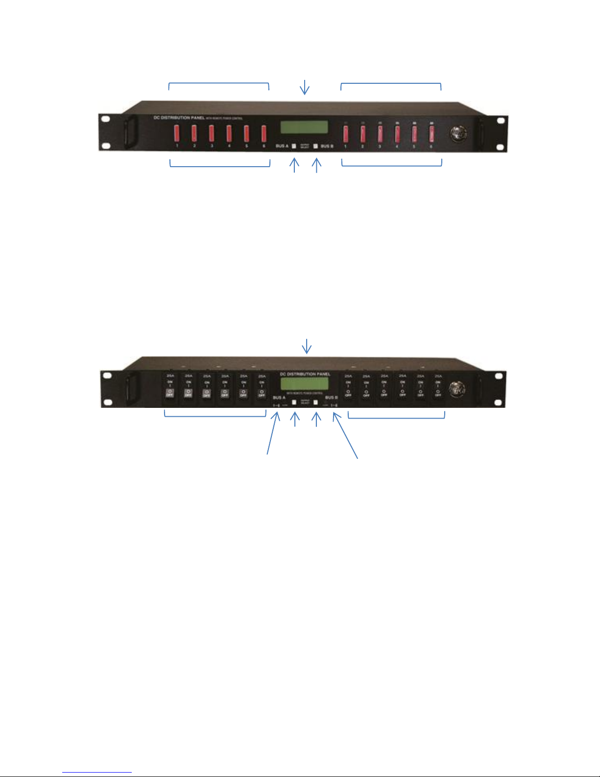
Figure 2: Fuse Version Front Panel
Energise each bus by closing the main external breaker or disconnect device on
the bus input lines. Check that the Distribution Panel LCD display powers up, the
internal channel relays close after a short delay, and the connected loads are
energised. (Note that all output channels on a bus will be disabled if the bus
voltage drops below 6V for more than 3s. Normal operation will be restored once
the bus voltage is above 8V)
Figure 3: Breaker Version Front Panel
Switch off any unused internal channel relays to reduce the power consumed by
the panel, using a connected computer and Web Browser. See the TCP/IP Web
Based Utility section, Output On/Off Buttons. (Each channel relay consumes
approximately 1W when closed)
LCD Display
At power up the LCD will be displaying the Bus A main screen showing the
voltage of that bus, and total current through the bus. Press the Bus A Output
Select button to cycle through the Network status page, the channel output
screens for that bus, (showing on/off status, voltage, and current for each output
channel on the bus selected) and the five Site Alarm input status screens (if alarm
inputs are enabled).
Pressing the Bus B Output Select button will switch the display to the Bus B
home screen. Press the button to cycle through the Network status page, each
LCD Output
select buttons
Bus A Output 1-6
fuses
Bus B Output 1-6
fuses
Bus A Output 1-6
fuse open LED’s
Bus B Output 1-6
fuse open LED’s
LCD Output
select buttons
Bus B Output 1-6
Circuit Breakers
Bus A Output 1-6
Circuit Breakers
BUS A Alarm LED
Bus B Alarm LED
LCD Display
LCD Display

10 Innovative Circuit Technology Ltd.
channel output screen for that bus, and the five Site Alarm input status screens
(if the alarm inputs are enabled).
Holding either Output Select button for 2 seconds will return the display to the
main screen for that bus. Holding either Output Select button for 20 seconds will
reset the password to the factory default. (see Password Reset section)
The LCD backlight will activate when pressing either Output Select button, and
will turn off after approximately 15 minutes of inactivity.
The LCD menu screens display the data as described below, in the sequence
shown in Figure 4, LCD Display Screens.
Main Screen
Line 1: The name of the panel (user configurable via the web based graphic
interface, default is “ICT Dual Bus Panel”)
Line 2: Displays the bus being monitored, Bus A or Bus B
Line 3: The system voltage (voltage will blink if the voltage exceeds the Under-
voltage or Over-voltage alarm thresholds)
Line 4: Total bus current (current will blink if the bus current exceeds the Over-
current alarm threshold)
Network Screen
Line 1: Network Status (Network Connected, No Network)
Line 2: Connection type (100Base-T, 10Base-T)
Line 3: IP address assigned to the panel
Line 4: MAC address of the panel
Output Screen (1A to 6A or 1B to 6B)
Line 1: Channel number, and name of load (User configurable, default is channel
number only)
Line 2: Channel output status (ENABLED, DISABLED to indicate internal relay
state or FUSE OPEN or BREAKER OFF if the over current device for the
channel is tripped)
Line 3: Output voltage (voltage will blink if it exceeds the Over or Under-voltage
alarm thresholds)
Line 4: Channel Output current (current will blink if it exceeds the Over, or
Under-current alarm threshold for that channel)
Each output channel may be given a unique name to describe the actual load
connected using the Output Setup section of the web based interface.
Site Alarm Input Screen (1 to 5)
 Loading...