

ICT ICT180S, ICT180S-12 Instruction Manual
THEPOWEROFRELIABILITY
INNOVATIVE CIRCUIT TECHNOLOGY LTD.
855-313-002
ICT DC DISTRIBUTION PANEL
LED
FUSE STATUS
ON
Blown or missing
OFF
Good
INSTRUCTION MANUAL
ICT180S-12 STANDARD MODEL
(SERIES 2)
INSTALLATION
1. Inspect panel and accessories to make sure everything is
complete and in good condition.
2. For rack set up, install panel on the rack using appropriate size
screws and star washers on all four mounting holes. If equipment
rack is not electrically connected to Earth ground, connect a ground
cable from the ground stud on the back of the panel to a known
Earth ground point. Otherwise, the four mounting screws and
washers are sufficient for earth ground connection.
OR
For non-rack set up, connect a ground cable from the ground stud
on the back of the panel to a known Earth ground point.
3. Remove the plastic shield(s) covering the output terminal
block(s) located on the back of the panel. Connect the positive of
the load to the positive terminal point (labeled “+”) and the
negative of the load to the negative terminal point (labeled “-“).
Table 1. Fuse Status LED
Table 2. Form “C” Alarm
4. Install fuse on the front of the panel for each output terminal block.
The fuse number on the front of the panel matches the output
terminal block number on the back of the panel. Use fuse size that
is
a few amps higher than the intended load. For terminal blocks with
no load connected, insert any size fuse to prevent the LED on the front
of the panel from turning on and the alarm from activating if the form
“C” alarm is used.
5. Remove the plastic caps covering the input insulated studs.
Connect the positive of the power source to the red insulated stud
(labeled “+”) and the negative of the power source to the black
insulated stud (labeled “-“).
6. Re-install plastic shield(s) to the output terminal block(s) and
plastic caps to the input studs.
7. For form “C” alarm monitoring, connect your external alarm circuit
to the alarm connector located on the back of the panel. Depending
on your alarm circuit (refer to table 2), you can connect it between
normally open (NO) and common (C), normally close (NC) and
common (C), or both. The alarm connector can be disconnected from
the panel for easy installation.
8. Power up the distribution panel, and check for proper operation of
the connected load(s), fuse status LEDs and form “C” alarm (if using).
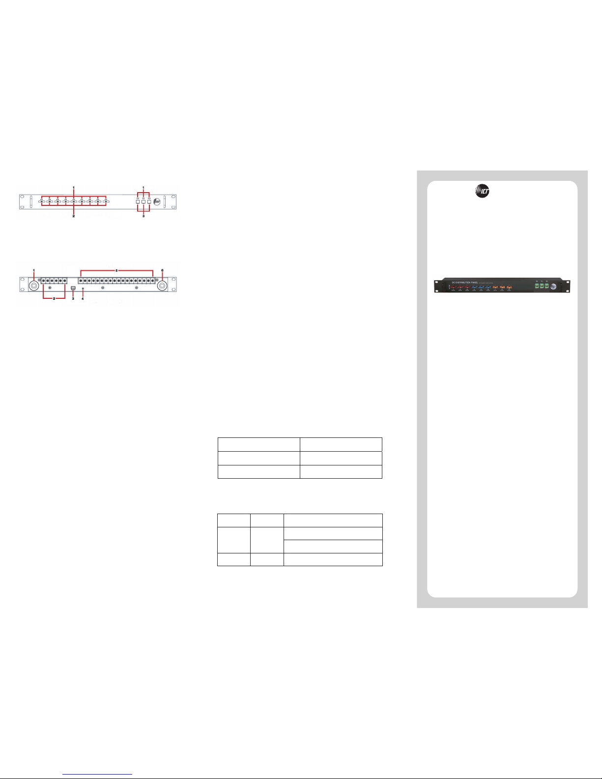
FRONT PANEL
1. FUSE STATUS LEDS: Turns on when a fuse is blown or missing.
2. ATO/ATC FUSES: Location of the ATO/ATC fuses up to 25A.
3. JCASE FUSES: Location of the JCASE fuses up to 40A.
BACK PANEL
1. NEGATIVE INPUT STUD: For DC power source connection up to
180A peak and 150A continuous.
2. OUTPUT TERMINAL BLOCK 10 – 12: For DC load connection up
to 40A each pair.
3. ALARM CONNECTOR: For external alarm circuit to monitor unit
fault.
4. CHASSIS GROUND STUD: For Earth ground connection.
5. OUTPUT TERMINAL BLOCK 1 - 9: For DC load connection up to
25A each pair.
6. POSITIVE INPUT STUD: For DC power source connection up to
180A peak and 150A continuous.
NC/C PINS NO/C PINS CONDITION
Open Closed
One or more blown or missing fuse
All fuses are good and inserted
Closed
Open
No power to unit

ICT Ltd. warrants to the original consumer purchaser that this
product shall be in good working order, free from defects in
materials and workmanship, for a period of three (3) years from the
date of purchase. Should failure occur during the above stated
time period, then ICT will, at its option, repair or replace this
product at no additional charge except as set forth below. All parts,
whether for repair or replacement, will be furnished on an
exchange basis. All exchange pieces become the property of ICT.
This limited warranty shall not apply if the ICT product has been
damaged by unreasonable use, accident, negligence, disaster,
service, or modification by anyone other than the ICT factory.
Limited warranty service is obtained by delivering the product
during the above stated three (3) years warranty period to an
authorized ICT dealer or ICT factory and providing proof of purchase
date. If this product is delivered by mail, you will insure the
product or assume risk of loss or damage in transit, and prepay
shipping charges to the factory.
Every reasonable effort has been made to ensure that ICT product
manuals and promotional materials accurately describe ICT product
specifications and capabilities at the time of publication. However,
because of ongoing improvements and updating of ICT products,
ICT cannot guarantee the accuracy of printed materials after the
date of publication and disclaims liability for changes, errors or
omissions.
If this ICT product is not in good working order, as outlined in the
above warranty, your sole remedy shall be repair or replacement as
provided above. In no event will ICT be liable for any damages
resulting from the use of or the inability to use the ICT product,
even if an ICT employee or an authorized ICT dealer has been
advised of the possibility of such damages, or for any claim by any
other party.
ICT reserves the right to make changes without further notice to
any products or documentation for improvement of reliability,
function, or design.
ICT Ltd. does not recommend use of its products in life support
applications wherein a failure or malfunction of the product may
directly or indirectly threaten life or cause injury. The user of ICT
products, which are to be used in life support applications as
described above, assumes all risks of such use and indemnifies ICT
against all damages.
LIMITED WARRANTY
INNOVATIVE CIRCUIT TECHNOLOGY LTD.
26921 GLOUCESTER WAY LANGLEY, BRITISH COLUMBIA, CANADA V4W 3Y3
T 604.856.6303 F 604.856.6365 www.ict-power.com
To reduce the risk of personal injury and property damage, please
exercise caution and follow the warnings below.
No user serviceable parts inside. Only ICT personnel are
authorized to service the unit
Keep sources of moisture away from the unit.
Read manual completely before starting installation or operation of
unit. Manual should be saved for future reference.
Observe correct polarities when making the input and output
connections.
Securely tighten all connections and insert fuses fully. Refer to
product specifications for maximum torque for the connectors.
Use appropriate wire size for both input and output connections.
Connect unit to an Earth ground point.
Turn off power source before installing/removing fuses,
connecting/disconnecting loads, or connecting/disconnecting
power source.
Allow input insulated studs and fuses to cool off before handling.
Depending on the current flowing through them, they may be too
hot to touch.
Do not connect any power source to the output terminal blocks.
Doing so will cause the fuse status LEDs and alarm to not work
properly.
It is recommended that the power source be equipped with current
limit protection.
WARNINGS
THEPOWEROFRELIABILITY
ICT STANDARD DC DISTRIBUTION PANEL
The ICT180S-12 Standard DC Distribution Panel was designed for
either 12 or 24VDC applications. It provides 12 output positions
that are individually protected by blade type fuses. Nine of the
outputs use the ATO/ATC blade fuse and are rated up to 25A each.
Three of the outputs use the JCASE fuse and are rated up to 40A
each. Each positive output terminal point is connected through a
fuse to a positive internal bus. All negative output terminal points
are connected to a negative internal bus.
Fuse status can be monitored through the LEDs. These fuses and
LEDs are located on the front of the Panel for easy monitoring and
replacement. Form “C” alarm contacts (C/NC/NO) are provided on
the back of the panel for an external alarm circuit. All these
features are packaged in a 1RU enclosure to save valuable rack
space, and 19” wide front plate to fit all standard 19” equipment
racks.
PRODUCT SPECIFICATIONS
O
perating Voltage:
10 to 32VDC
Panel Capacity:
150A (Continuous)
180A (Peak)
Fuse Capacity:
25A Max ATO/ATC Blade x 9
40A Max JCASE x 3
Voltage Drop (without fuse):
60mV (Typical)
A
larm Contact:
Form “C” Dry Contacts
1A/60VDC Max
Input Connector:
Heavy Duty Insulated M10 Stud
75in-lbs Max
-
Output Connector:
Barrier Terminal Block
M4 Screws
8-20AWG Wire Range
12in - lbs Max
A
larm Connector:
Euro Terminal Block
M2 Screws
16-28AWG Wire Range
1in-lbs Max
Operating Temperature:
-4°F to 140°F
-20°C to +60°C
Dimensions:
19.0” x 5.4” x 1.75”
483mm x 137mm x 45mm
Weight:
4.0lbs
1.8kg
Warranty:
3 years
 Loading...