

ICT ICT1500-12SW, ICT1500-24SW, ICT1500A-12SW, ICT1500-48SW, ICT1500A-48SW Instruction Manual
...
1500W Sine Wave Series
Inverter
INSTRUCTION MANUAL
855-151-000
Innovative Circuit
Technology Ltd.
Models:
ICT1500-12SW ICT1500A-12SW
ICT1500-24SW ICT1500A-24SW
ICT1500-48SW ICT1500A-48SW

2 Innovative Circuit Technology Ltd.
WARNING
Risk of serious personal injury or damage to equipment and property! Always
observe the following:
Use an appropriately rated over-current protection device in line with the
main battery connection to the Inverter
Use an appropriately rated over-current protection device in line with the ac
input connection to the Inverter (if transfer relay option is installed)
Use an appropriately rated disconnect switch or circuit breaker in line with
the Inverter dc and ac inputs to enable installation and service with the
battery and ac power source disconnected
Shut off or disconnect the dc and ac power sources before connecting or
disconnecting wiring
Use wire and connectors rated for the maximum load current and size of
fuse or circuit breaker, and keep cable lengths as short as practical
Ensure battery voltage matches the rating of the model of inverter in use
Carefully observe wiring polarity when making input connections
Securely tighten all connections
Install the wiring box and cover and use appropriate wiring strain relief
devices on all wires
The ac NEUTRAL line may be internally bonded to the chassis (if ground
bonding screw is installed). Ensure chassis is connected to earth ground
before use
Batteries can explode or arc! Wear suitable face and hand protection and
use insulated tools when working with batteries
Do not attempt to service any internal parts. Refer all product service to an
authorized ICT Ltd. service facility
CAUTION
Risk of personal injury or damage to equipment! Always observe the following:
Install in a protected environment, keep sources of moisture away from unit
Ensure the total power consumption of the load does not exceed the rated
load capacity of the inverter
Do not block air inlet or outlet openings in the inverter

Innovative Circuit Technology Ltd. 3
Contents
INTRODUCTION .................................................................................. 4
INSTALLATION .................................................................................... 4
OPERATION ........................................................................................ 8
Status Indicators and Alarms ......................................................... 9
AC Transfer Switch (Option “T”) .................................................. 10
TCP/IP WEB BASED UTILITY OPTION ................................................ 11
Status and Control ....................................................................... 12
Device Setup ................................................................................ 13
Network setup ............................................................................. 14
E-mail Setup ................................................................................. 17
User Setup .................................................................................... 18
Maintenance ................................................................................ 20
MOBILE WEB APP ............................................................................. 21
PASSWORD and IP ADDRESS RESET ................................................. 21
ROUTER CONFIGURATION ............................................................... 22
TEXT MESSAGE ALARM NOTIFICATIONS .......................................... 24
TROUBLESHOOTING ......................................................................... 24
PRODUCT SPECIFICATIONS .............................................................. 26
LIMITED WARRANTY ........................................................................ 28

4 Innovative Circuit Technology Ltd.
INTRODUCTION
The ICT1500 Sine Wave Series is a compact high efficiency true sine wave output
DC to AC inverter with features optimized for commercial applications:
Unparalleled power density at 1500W, with 3000W surge capability
115Vac 60Hz and 230Vac 50Hz models, with 93% peak efficiency
Optional TCP/IP Ethernet port with built in web-server, and support for
SNMP v1/v2 management systems for remote control and monitoring
Optional DC wiring box for code compliant standalone installations
19" dual inverter rack mounting with optional kit for installing 2 units side
by side in 1.5U of rack space
Low idle current draw
Form C alarm contacts for remote notification of alarms
Optional automatic transfer switch with user definable trip levels
Low EMI, FCC Class A compliance
AC front convenience outlets or rear hardwire AC connections standard
Temperature controlled variable speed fan for low noise and long life
Model Numbers and Options (factory installed):
115Vac 60Hz
Models
230Vac 50Hz
Models1
Battery V Description
ICT1500-12SW
ICT1500-24SW
ICT1500-48SW
ICT1500A-12SW
ICT1500A-24SW
ICT1500A-48SW
12
24
48
1500W True Sine Wave
inverter
ICT1500-12SWT
ICT1500-24SWT
ICT1500-48SWT
ICT1500A-12SWT
ICT1500A-24SWT
ICT1500A-48SWT
12
24
48
1500W inverter with
AC transfer switch
option
ICT1500-12SWC
ICT1500-24SWC
ICT1500-48SWC
ICT1500A-12SWC
ICT1500A-24SWC
ICT1500A-48SWC
12
24
48
1500W inverter with
Ethernet/SNMP
communication option
ICT1500-12SWTC
ICT1500-24SWTC
ICT1500-48SWTC
ICT1500A-12SWTC
ICT1500A-24SWTC
ICT1500A-48SWTC
12
24
48
1500W inverter with
AC transfer switch and
Ethernet/SNMP option
Optional Accessories:
19 inch rack mounting kit (mount up to 2 inverters): ICT-RMK4
Wiring Junction Box (attaches to back of inverter): ICT-DCWB
INSTALLATION
Perform a quick physical check of the unit as it is being taken out of the box to
ensure it has not been damaged during shipping. Check for the included parts
and accessories shipped with your unit:
1
Models with Australasian IEC type I front AC outlet shown

Innovative Circuit Technology Ltd. 5
3 pin Form-C alarm connector plug
Wall mounting bracket, with mounting screws (4), installed
Instruction Manual
Bus bar connection 5/16 inch bolt, nut, and washer set (2)
Mount the optional wiring junction box base (part of the Wiring Junction Box kit
ICT-DCWB) to the back of the inverter with 4 supplied screws, as shown in Figure
1. Knockout the plugs and install conduit fittings or wire strain relief clamps in
the wiring box openings to be used for the installation, as required. The inverter
must be installed in a restricted access environment such as an enclosed
equipment rack if the back panel wiring junction box is not used.
Figure 1: Wiring Junction Box Installation
Mount the inverter using the wall mount bracket (included) or the optional 19
inch rack-mount tray (ICT-RMK4) using the 4 mounting screws on the bottom of
the inverter, as illustrated in Figure 2. Keep the distance to the battery bank as
short as practical to minimize power loss in the high current wiring. (see DC Wire
Sizing Guide table)
Figure 2: Inverter Wall Bracket Mounting
6 Innovative Circuit Technology Ltd.
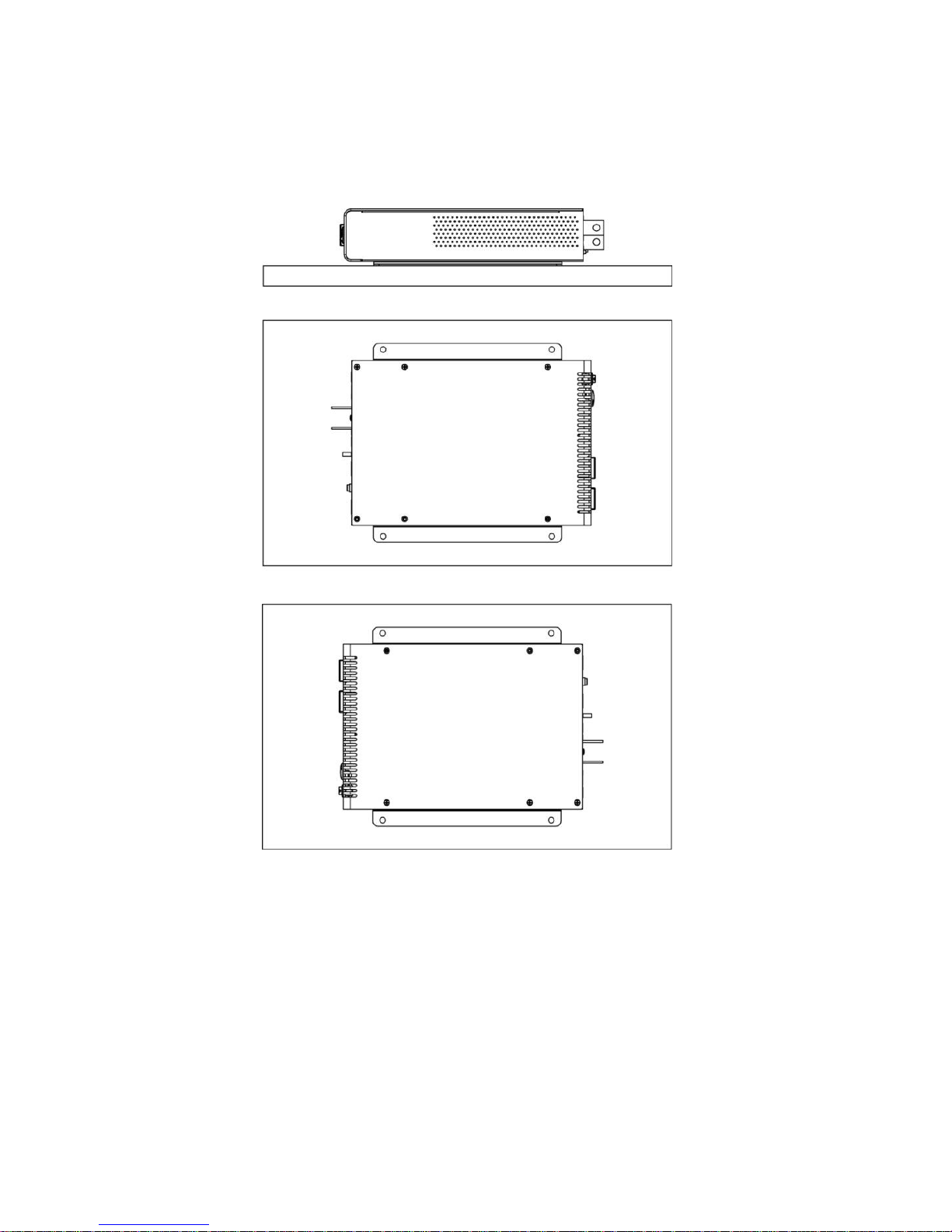
The inverter may be mounted horizontally on a shelf, or the ICT rack tray, or in a
vertical wall mounted orientation. Install the unit with either side located on top
(as shown in Figure 3) when wall mounting to ensure proper cooling and long
term safe operation of the inverter. (Mounting hardware not included)
Figure 3: Approved Mounting Orientations
Connect the chassis ground stud on the back panel to a reliable earth ground
point.
Ensure the inverter switch is in the off position, then connect the dc input wiring
from a suitable deep-cycle lead-acid battery to the inverter using appropriately
rated wire size (see DC Wire Sizing Guide), and an in line over current protection
device/disconnect switch or breaker (with disconnect switch in “off” position).
Terminate wire with appropriate size of ring tongue to fit the 5/16” input bus bar
mounting bolts.
Innovative Circuit Technology Ltd. 7
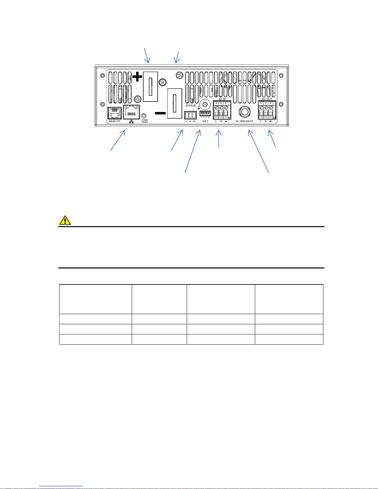
Figure 4: Back Panel Connections
CAUTION
Risk of personal injury or damage to equipment!
Ensure the nominal battery voltage is correct for the model of inverter, and that
the battery positive is connected to the inverter input positive (+) terminal,
battery negative is connected to the inverter negative (-) terminal.
Table 1 : DC Wiring Minimum Sizing Guide, Recommended Minimum Battery Size
Connect the AC loads to be powered by the inverter to the AC OUT wire clamp
connector (Line, Neutral and Ground) located on the back panel, (see Figure 4)
using wire rated for 15A. (14 – 12AWG) Alternatively cord connected devices
may be directly plugged in to the AC outlets located on the inverter front panel.
On units with the Transfer Relay (option “T”) connect the external AC power
source (grid power, or AC generator) to the AC IN wire clamp connector on the
back panel of the inverter, using wire rated for at least 15A (14 – 12AWG), with
the AC power source switched off.
Distance from
Inverter to Battery
12V input
(100Ah min
battery)
24V input
(50Ah min
battery)
48V input
(25Ah min
battery)
0 – 5 feet
1 AWG
6 AWG
8 AWG
5 – 10 feet
2/0 AWG
4 AWG
6 AWG
10 – 20 feet
4/0 AWG
2 AWG
4 AWG
AC Output to load
L-N-G
External AC Input
(Option “T”) L-N-G
Alarm Contacts
C-NC-NO
10/100 Base-T
Ethernet Port
(Option “C”)
NEG Input from
Battery
POS Input from
Battery with
Breaker or Fuse
AC Transfer V
Setting Switch
15A Output Circuit
Breaker

8 Innovative Circuit Technology Ltd.
CAUTION
Risk of personal injury or damage to equipment!
AC input wiring from the grid or other power source to the inverter must be
protected using a branch rated circuit breaker of 15A or lower value.
Connect the external alarm monitoring wiring to the Form-C alarm contact
output if desired. (See Alarm Output Contacts table, below) Plug the Ethernet
network (CAT-5) cable in to the optional Network port on the back panel (option
“C” equipped units only), routing the alarm and network cable through the
plastic bushing immediately adjacent to the connector on the side of the optional
wiring box tray.
Alarm Pin
Name
Description
1
C
Alarm output common
2
NC
Alarm output Normally
Closed contact
3
NO
Alarm output Normally
Open contact
Table 2: Alarm Output Contacts
Check that all connections to the inverter are correct and tight, then tighten the
wire strain relief clamps in the wiring junction box (if used), and install the wiring
box cover.
Set the external battery disconnect switch or breaker to “on”.
OPERATION
With the unit mounted, wired, and powered as described in the INSTALLATION
section, turn the front panel power switch to the ON position and check that the
green AC indicator on the front panel is flashing slowly, indicating the inverter
battery powered AC output is on.
Switch the external ac source disconnect device to ON (if an external AC source is
being used, Transfer Switch option “T” only), and observe that the green AC
indicator on the front panel is now on continuously, indicating the external AC
source is present and powering the load. The inverter output will now be
powered directly from the external AC source.
The connected AC loads should now be operating normally, powered with up to
1500W (3000W momentary peak) of battery backed AC power.

Innovative Circuit Technology Ltd. 9
Figure 5: Front Panel
Status Indicators and Alarms
The 3 LEDs on the front panel and the Form-C alarm contacts on the back
indicate the status of the inverter:
Alarm or
Notification
Trigger Condition
Inverter
Output
Red
FAULT
LED
Yellow
WARN
LED
Green
AC
LED
Inverter AC
Output OK
(Battery Backup
Mode)
Normal operation,
output above 90VAC
(or 180Vac, 230V
models)
Enabled
- - BLINK
External AC
Voltage OK
AC input (Transfer
Relay option only) is
above set limit, and is
powering the output
Enabled
- - ON
DC Undervoltage
Warning
Triggers when Input
Voltage drops below
11.0/22.0/44.0VDC for
1 s. Clears when input
is above 11.2/ 22.4/
44.8V for 1s.
Enabled
-
ON
-
Remote
Shutdown
Triggers when Remote
Shutdown is activated
over optional Ethernet,
or remote panel switch
OFF
BLINK
-
OFF
System Fault
Indicates internal
circuit fault - Clears
when all fault
conditions are cleared.
OFF
ON - OFF
DC Undervoltage
Triggers when Input
OFF
ON - OFF
Green AC Indicator
- Inverter on (flash)
- Grid power (continuous)
Yellow - Low Battery
Warning
Red - Fault
AC Outlets:
2 x NEMA 5-15R (115V)
Or 1 x IEC type I (230V)
Inverter On/Off Switch
 Loading...