

ICT ICT103048-5AI2, ICT1212-35AI2, ICT206012-12AI2, ICT206012-20AI2, ICT206024-10AI2 Instruction Manual
...
THEPOWEROFRELIABILITY
INNOVATIVE CIRCUIT TECHNOLOGY LTD.
855-315-004
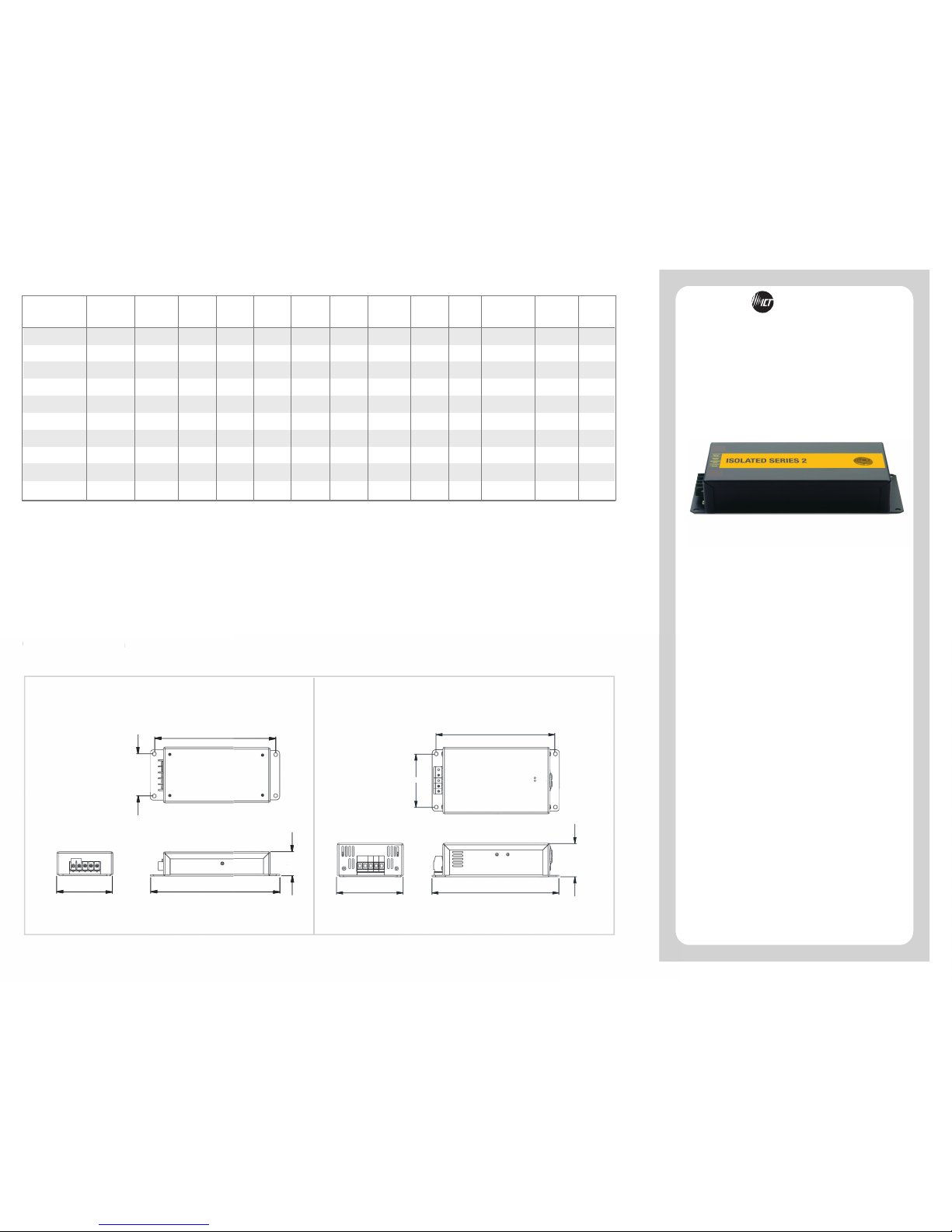
ICT ISOLATED SERIES 2
INSTRUCTION MANUAL
CONVERTERS
OUTLINE DRAWING
DIMENSIONS IN INCHES
OUTLINE DRAWING
1.77
9.504.10
8.90
3.10
1.77
2.45
9.35
8.75
3.92
4.90
Drawing A Drawing B
Input
Voltage
Range
Output
Voltage
Output
Current
(Cont.)
Output
Current
(Peak)
Current
Limiting
Line
Regulation
Load
Regulation
Output
Ripple
(Max)
Efficiency
(Typical)
ICT1212-12AI2
ICT1212-35AI2
ICT1224-10AI2
11-18 VDC
13.8 VDC
+/- 150 mV
10.0 Amps 12.0 Amps
12.5 Amps
+/- 5%
20mV RMS 88%
Input
Fuse
20 Amp
60 Amp
35 Amp
13.8 VDC
+/- 150 mV
32.0 Amps 35.0 Amps
35.5 Amps
+/- 5%
20mV RMS 90%
11-18 VDC
11-18 VDC
27.6 VDC
+/- 300 mV
8.0 Amps 10.0 Amps
10.5 Amps
+/- 5%
30mV RMS 90%
Model
Number
0.5% 0.5%
0.5% 0.5%
0.5% 0.5%
Dimensions
Drawing A
Drawing A
Drawing B
Operating
Temperature
Range
-20°C to +40°C
-20°C to +40°C
-20°C to +40°C
0.5%
20-60 VDC
4.0 Amps 5.0 Amps
5.5 Amps
+/- 5%
20-60 VDC
13.8 VDC
+/- 150 mV
10.0 Amps 12.0 Amps
12.5 Amps
+/- 5%
8.0 Amps 10.0 Amps
10.5 Amps
+/- 5%
13.8 VDC
+/- 150 mV
32.0 Amps 35.0 Amps
35.5 Amps
+/- 5%
17.0 Amps 20.0 Amps
20.5 Amps
+/- 5%
20-60 VDC
11-30 VDC
27.6 VDC
+/- 300 mV
20-60 VDC
48.0 VDC
+/- 300 mV
13.8 VDC
+/- 150 mV
90%
90%
35 Amp
15 Amp
20 Amp
20 Amp
40 Amp
ICT103048-5AI2
ICT206012-12AI2
ICT206012-20AI2
ICT206024-10AI2
ICT206012-35AI2
ICT1224-20AI2
30mV RMS 90%
20mV RMS 88%
30mV RMS
20mV RMS
20mV RMS 90%
60 Amp17.0 Amps 20.0 Amps
20.5 Amps
+/- 5%
30mV RMS 90%11-18 VDC
27.6 VDC
+/- 300 mV
0.5%
0.5% 0.5%
0.5% 0.5%
0.5% 0.5%
0.5% 0.5%
0.5% 0.5%
Drawing A
Drawing A
Drawing A
Drawing A
Drawing B
Drawing B
-20°C to +40°C
-20°C to +40°C
-20°C to +40°C
-20°C to +40°C
-20°C to +40°C
-20°C to +40°C
1. The REMOTE control input requires a voltage between 10VDC and 60VDC referenced to the input ground to enable the output of the converter.
Converters ship with a jumper connecting the REMOTE input and the input positive terminal, which must be removed before the control feature will function.
SPECIFICATIONS
2. The REMOTE control will disable the converter when the remote terminals connected to the INPUT NEG terminal of the converter. The converter is enabled
when the REMOTE terminal is left floating.
Remote
Terminal
Operation
Note 1)
Note 1)
Note 1)
Note 1)
Note 1)
Note 1)
Note 1)
Note 1)
Note 1)
27.6 VDC
+/- 300 mV
18.0 Amps 20.0 Amps
21 Amps
+/- 5%
20-60 VDC 90% 40 Amp
ICT206024-20AI2
30mV RMS0.5% 0.5%
Drawing B
-20°C to +40°C
Note 1)

LIMITED WARRANTY
INNOVATIVE CIRCUIT TECHNOLOGY LTD.
26921 GLOUCESTER WAY LANGLEY, BRITISH COLUMBIA, CANADA V4W 3Y3
T 604.856.6303 F 604.856.6365 www.ict-power.com
ICT Limited Warranty is only intended for the benefit of the original
Purchaser of this product. This Warranty is not transferable or
assignable without the prior written permission of ICT. ICTʼs sole
obligation and liability under this warranty is limited to either repairing
or replacing defective products at the sole discretion of ICT. When
repairing or replacing the products, ICT may use products or parts
that are new, equivalent to new or re-conditioned. Parts repaired or
replaced during the warranty period will be under warranty for the
remainder of the warranty period.
The warranty period on ICT products purchased new from ICT is two
years. The warranty period for a repaired product or part thereof is
ninety (90) days or the remainder of the unexpired term of the new
product warranty period, whichever is greater. Repair or replacement
of a defective product or part does not extend the original warranty
coverage period.
No claim will be accepted unless written notice of the claim is
received by ICT in accordance with ICTʼs Return Material
Authorization (RMA) procedure, as soon as reasonably possible
after the defect is discovered. A valid product serial number must be
provided with the RMA claim to prove eligibility. The RMA form is
available on the ICT website at
www.ict-power.com/support/warranty-repair/.
The Purchaser shall at their own risk and cost return the defective
product to ICTʼs factory or designated repair center once an RMA is
issued by ICT. Return of the products to the customer after repair is
completed shall be prepaid by ICT unless otherwise mutually agreed
between the parties. Products shipped to ICT which have incurred
freight damage will not be covered by this Warranty and any repairs
or replacement parts, components or products needed will be
invoiced in the full current price amount and returned freight collect
to Purchaser. It is the Purchaserʼs responsibility to check the product
upon receipt for any damage during shipping and to contact the
carrier or shipper regarding such damage. Product that is returned
as defective, which is determined to operate within published
specifications will be returned to the Purchaser freight collect.
This Warranty will be void if the product has been subjected to
misuse, neglect, accident, exposure to environmental conditions not
conforming to the productsʼ limits of operation, improper installation
or maintenance, improper use of an electrical source, defects
caused by sharp items or by impact pressure, a force majeure event,
has been modified or repaired by anyone other than ICT or its
authorized representative, has been subjected to unreasonable
physical, thermal or electrical stress, improper maintenance, or
causes external to the unit including but not limited to general
environmental conditions such as rust, corrosive atmospheres,
sustained temperatures outside the specified operating range of the
equipment, exposure to power surges and/or electrical surges,
improper grounding, mould or dust, animal or insect damage, water
damage or immersion in liquid of any kind.
ICT does not control the installation and use of any ICT product.
Accordingly, it is understood this does not constitute a warranty of
performance or a warranty of fitness for a particular purpose.
THEPOWEROFRELIABILITY
NOTES
These converters incorporate a special noise filter
design. For proper filtering, the converter chassis
must be grounded.
The continuous current ratings are for 40°C ambient
temperatures. Please de-rate the output current rating
2%/
°
C for operating from 40°C to 60°C ambient
temperatures.
4
4
Remove the cover to check fuse inside the unit. If
blown, replace it only with a fuse of the same rating.
Check for proper voltage at the input while converter is
under load.
Check for any erratic voltage conditions at the input
that might trigger the overvoltage protection.
4
4
4
TROUBLESHOOTING
Incorrect wiring may damage both the converter
and any equipment connected.
Do not place the unit on or near any sources of
heat and moisture.
Servicing of unit should be done only at ICT factory.
4
4
4
WARNING
ICT ISOLATED SERIES 2 CONVERTERS
SETUP
ICT ISOLATED SERIES 2 DC-DC converters feature an
all-new design that builds on the ICT legacy of reliability
and performance. This line delivers higher efficiency
and an on/off control contact to help save energy and
battery life.
ISOLATED SERIES 2 converters can operate from a
negative or positive ground electrical system, and are
ideal for applications where complete isolation is
necessary between primary and secondary circuits, as
well as from the chassis.
These instructions should be read before using the
product and saved for future reference.
Mount converter securely.
Do not apply power until the unit is completely
wired.
4
4
4
4
4
4
Default Configuration From Factory
All models are output-enabled by factory default:
> For models ICT206012-35AI2, ICT206024-20AI2,
ICT1212-35AI2 and ICT1224-20AI2, a jumper is
installed between the two REMOTE terminals.
> For all other models, a jumper is installed
between the REMOTE terminal and the INPUT
POS terminal.
Remote On/Off Feature
To use the remote on/off feature, remove the
jumper.
> For models ICT206012-35AI2, ICT206024-20AI2,
ICT1212-35AI2 and ICT1224-20AI2, short/open the
REMOTE CONTROL terminals to turn the unit
on/off.
> For all other models apply the input voltage to the
REMOTE terminal to enable the output.
Connect load to the output.
Connect power source to the input using
appropriate fusing for the application
For the best results, wire converter directly to the
battery using heavy gauge wire.
 Loading...