

ICT ICT12012-12A, ICT12012-30A, ICT12012-20A, ICT12012-15A, ICT12024-10A Instruction Manual
...
THEPOWER
OFRELIABILITY
INNO
VATIVE CIRCUIT TECHNOLOGY LTD.
855-040-007
ICT COMM SERIES
INSTRUCTION MANUAL
48VDC Output
40 mV RMS
90-130 VAC
48.0 VDC
+/- 150 mV
4.0 Amps 5.0 Amps 5.5 Amps 0.50% 1.00% 80%
ICT12048-5A
7.10 2.507.60
Input
Voltage
Range
Output
Voltage
Output
Current
(Cont.)
Output
Current
(Peak)
Current
Limiting
Line
Regulation
Load
Regulation
Output
Ripple
(Max)
Efficiency
(Typical)
Dimensions (inches)
W HLModel Number
90-130 VAC
27.6 VDC
+/- 150 mV
8.0 Amps 10.0 Amps 10.5 Amps 0.20% 0.75% 20 mV RMS 85%
ICT12024-10A
90-130 VAC
27.6 VDC
+/- 150 mV
13.0 Amps 15.0 Amps 15.5 Amps 0.20% 0.75% 20 mV RMS 85%
ICT12024-15A
90-130 VAC
27.6 VDC
+/- 150 mV
5.5 Amps
ICT12024-5A
0.20% 0.75% 20 mV RMS 85%4.0 Amps 5.0 Amps
7.10 1.807.60
7.10 2.507.60
7.10 2.507.60
Input
Voltage
Range
Output
Voltage
Output
Current
(Cont.)
Output
Current
(Peak)
Current
Limiting
Line
Regulation
Load
Regulation
Output
Ripple
(Max)
Efficiency
(Typical)
Dimensions (inches)
W HLModel Number
24VDC Output
90-130 VAC
13.8 VDC
+/- 150 mV
90-130 VAC
13.8 VDC
+/- 150 mV
90-130 VAC
13.8 VDC
+/- 150 mV
13.0 Amps 15.0 Amps 15.5 Amps 0.20% 0.80% 20 mV RMS 85%
ICT12012-15A*
90-130 VAC
13.8 VDC
+/- 150 mV
17.0 Amps 20.0 Amps 20.5 Amps 0.20% 0.85% 20 mV RMS 85%
ICT12012-20A*
90-130 VAC
13.8 VDC
+/- 150 mV
25.0 Amps 30.0 Amps 31.0 Amps 0.20% 0.85% 20 mV RMS 85%
ICT12012-30A*
ICT12012-10A*
ICT12012-12A*
7.5 Amps 10.0 Amps 10.5 Amps 0.20% 0.75% 20 mV RMS 85%
10.0 Amps 12.0 Amps 12.5 Amps 0.20% 0.80% 20 mV RMS 85%
See Tech Note* 1.807.60
See Tech Note* 1.807.60
See Tech Note* 2.507.60
See Tech Note* 2.507.60
See Tech Note* 2.507.60
Input
Voltage
Range
Output
Voltage
Output
Current
(Cont.)
Output
Current
(Peak)
Current
Limiting
Line
Regulation
Load
Regulation
Output
Ripple
(Max)
Efficiency
(Typical)
Dimensions (inches)
W HL
Model Number
12VDC Output
SPECIFIC
ATI
ONS
*A
- Standard 7.1" Width
*AG - 6.4" Width
13.8 VDC
+/- 150 mV
13.0 Amps 15.0 Amps 15.5 Amps 0.20% 0.80% 20 mV RMS 85%
ICT22012-15A
61190
Input
Voltage
Range
Output
Voltage
Output
Current
(Cont.)
Output
Current
(Peak)
Current
Limiting
Line
Regulation
Load
Regulation
Output
Ripple
(Max)
Efficiency
(Typical)
Dimensions (mm)
W HL
Model Number
180-250 VAC
50/60Hz
13.8 VDC
+/- 150 mV
ICT22012-10A
7.5 Amps 10.0 Amps 10.5 Amps 0.20% 0.75% 25 mV RMS 85%
43190
180
180
180-250 VAC
50/60Hz
13.8 VDC
+/- 150 mV
17.0 Amps 20.0 Amps 20.5 Amps 0.20% 0.85% 25 mV RMS 85%
ICT22012-20A
61190
180
180-250 VAC
50/60Hz
13.8 VDC
+/- 150 mV
25.0 Amps 30.0 Amps 31.0 Amps 0.20% 0.85% 25 mV RMS 85%
ICT22012-30A
61190
180
180-250 VAC
50/60Hz
13.8 VDC
+/- 150 mV
25.0 Amps 30.0 Amps 31.0 Amps 0.20% 0.85% 25 mV RMS 85%
ICT22012-30AG
61190
163
180-250 VAC
50/60Hz
13.8 VDC
+/- 150 mV
17.0 Amps 20.0 Amps 20.5 Amps 0.20% 0.85% 25 mV RMS 85%
ICT22012-20AG
61190
163
180-250 VAC
50/60Hz
180-250 VAC
50/60Hz
13.8 VDC
+/- 150 mV
ICT22012-12AG
10.0 Amps 12.0 Amps 12.5 Amps 0.20% 0.80% 20 mV RMS 85%
43190
163
(a)
220 VAC Input
This device complies with Part 15 of the FCC Rules. Operation is
subject to the following 2 conditions:
1. This device may not cause harmful interference, and
2. This device must accept any interference received, including
any interference that may cause undesired operation.
LIMITED WARRANTY
INNOVATIVE CIRCUIT TECHNOLOGY LTD.
26921 GLOUCESTER WAY LANGLEY, BRITISH COLUMBIA, CANADA V4W 3Y3
T 604.856.6303 F 604.856.6365 www.ict-power.com
ICT Limited Warranty is only intended for the benefit of the original
Purchaser of this product. This Warranty is not transferable or
assignable without the prior written permission of ICT. ICT’s sole
obligation and liability under this warranty is limited to either repairing
or replacing defective products at the sole discretion of ICT. When
repairing or replacing the products, ICT may use products or parts that
are new, equivalent to new or re-conditioned. Parts repaired or
replaced during the warranty period will be under warranty for the
remainder of the warranty period.
The warranty period on ICT products purchased new from ICT is two
years. The warranty period for a repaired product or part thereof is
ninety (90) days or the remainder of the unexpired term of the new
product warranty period, whichever is greater. Repair or replacement
of a defective product or part does not extend the original warranty
coverage period.
No claim will be accepted unless written notice of the claim is received
by ICT in accordance with ICT’s Return Material Authorization (RMA)
procedure, as soon as reasonably possible after the defect is
discovered. A valid product serial number must be provided with the
RMA claim to prove eligibility. The RMA form is available on the ICT
website at www.ict-power.com/support/warranty-repair/.
The Purchaser shall at their own risk and cost return the defective
product to ICT’s factory or designated repair center once an RMA is
issued by ICT. Return of the products to the customer after repair is
completed shall be prepaid by ICT unless otherwise mutually agreed
between the parties. Products shipped to ICT which have incurred
freight damage will not be covered by this Warranty and any repairs or
replacement parts, components or products needed will be invoiced in
the full current price amount and returned freight collect to Purchaser.
It is the Purchaser ’s responsibility to check the product upon receipt
for any damage during shipping and to contact the carrier or shipper
regarding such damage. Product that is returned as defective, which
is determined to operate within published specifications will be
returned to the Purchaser freight collect.
This Warranty will be void if the product has been subjected to misuse,
neglect, accident, exposure to environmental conditions not
conforming to the products’ limits of operation, improper installation or
maintenance, improper use of an electrical source, defects caused by
sharp items or by impact pressure, a force majeure event, has been
modified or repaired by anyone other than ICT or its authorized
representative, has been subjected to unreasonable physical, thermal
or electrical stress, improper maintenance, or causes external to the
unit including but not limited to general environmental conditions such
as rust, corrosive atmospheres, sustained temperatures outside the
specified operating range of the equipment, exposure to power surges
and/or electrical surges, improper grounding, mould or dust, animal or
insect damage, water damage or immersion in liquid of any kind.
ICT does not control the installation and use of any ICT product.
Accordingly, it is understood this does not constitute a warranty of
performance or a warranty of fitness for a particular purpose.
NOTES
The ICT Comm Series can be used in parallel or series
configurations. Please contact ICT for further information.
Most ICT Comm series products are available in two widths
(A = 7.11", AG = 6.4") and can be assembled with a wide
variety of ICT base station covers. 120 / 220 Volt or 220 Volt
input models are available, as well as 12 and 24 V output
models. Options available also include an LCD meter for
current and voltage display, and a 19" rackmount
configuration. Wallmount brackets are available for permanent
installation. (part #ICT-WMB)
The ICT Comm Series can also be used to charge a battery
while powering an accessory without any modification. Please
contact ICT for design note (DN-101 Battery backup).
4
4
4
Do not block side or bottom vent slots.
Do not place unit on or near sources of heat/moisture.
Incorrect wiring may result in serious damage to both power
supply and equipment wired to power supply.
Unit service should be done by ICT.
SETUP
ICT COMM SERIES
WARNING
The ICT Comm Series switching power supplies deliver continuous
trouble-free operation and incorporate extra filtering, providing a
virtually noise-free environment for a wide range of
communications equipment and 12V and 24V accessories.
These instructions should be read before using the product and it
should be saved for future reference.
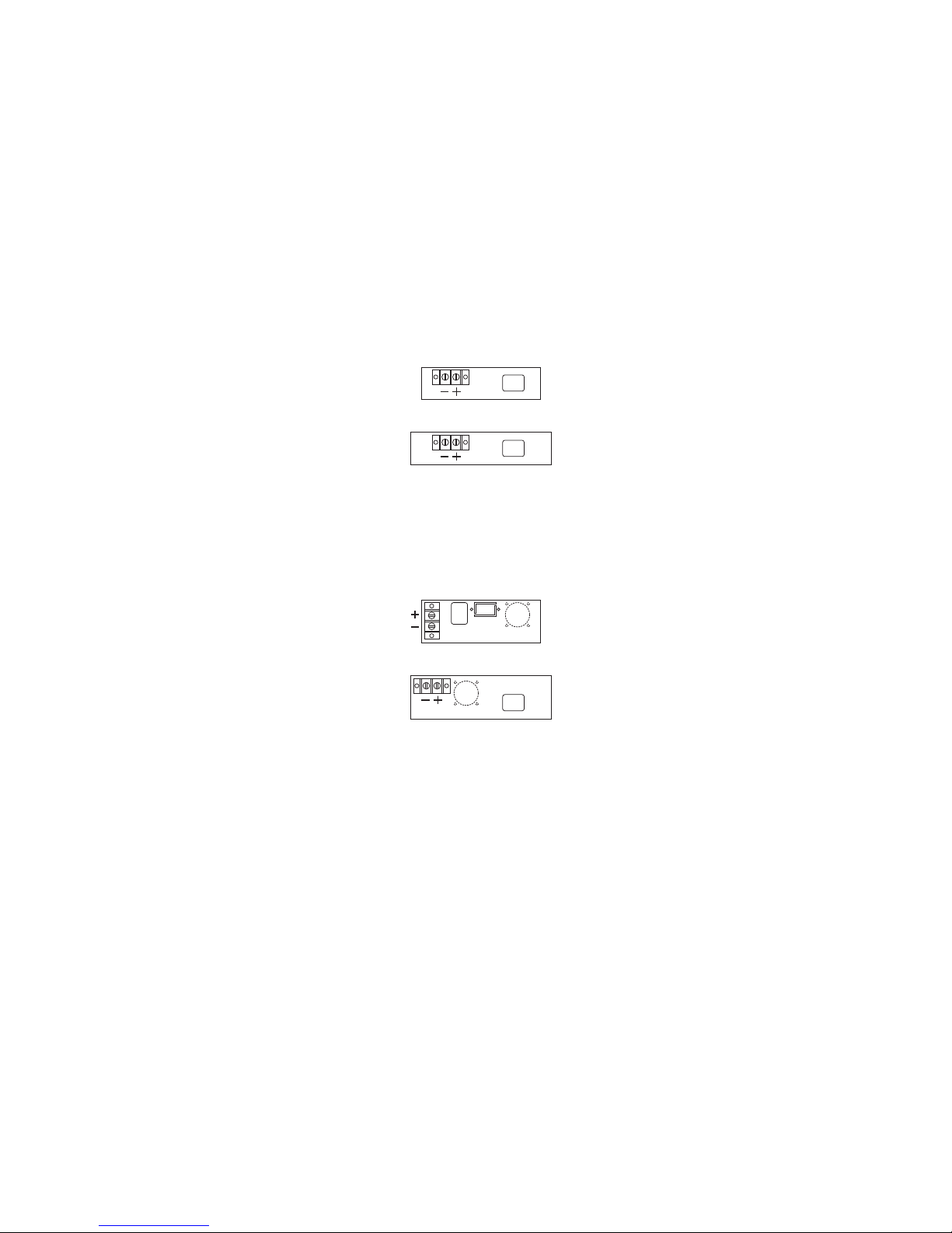
Plug the enclosed power cord into the input plug on the back
of the unit. Plug the other end into the AC outlet.
Connect equipment to terminal block at the rear of the unit.
Note: Keep the hook-up leads to the load as short as possible
to avoid excess radiated noise.
To turn on power supply, press top of front panel switch.
4
4
4
4
4
4
4
AG
A
AG
A
CONNECTIONS
100 - 200 watts
200 - 500 watts
 Loading...