

Page 1
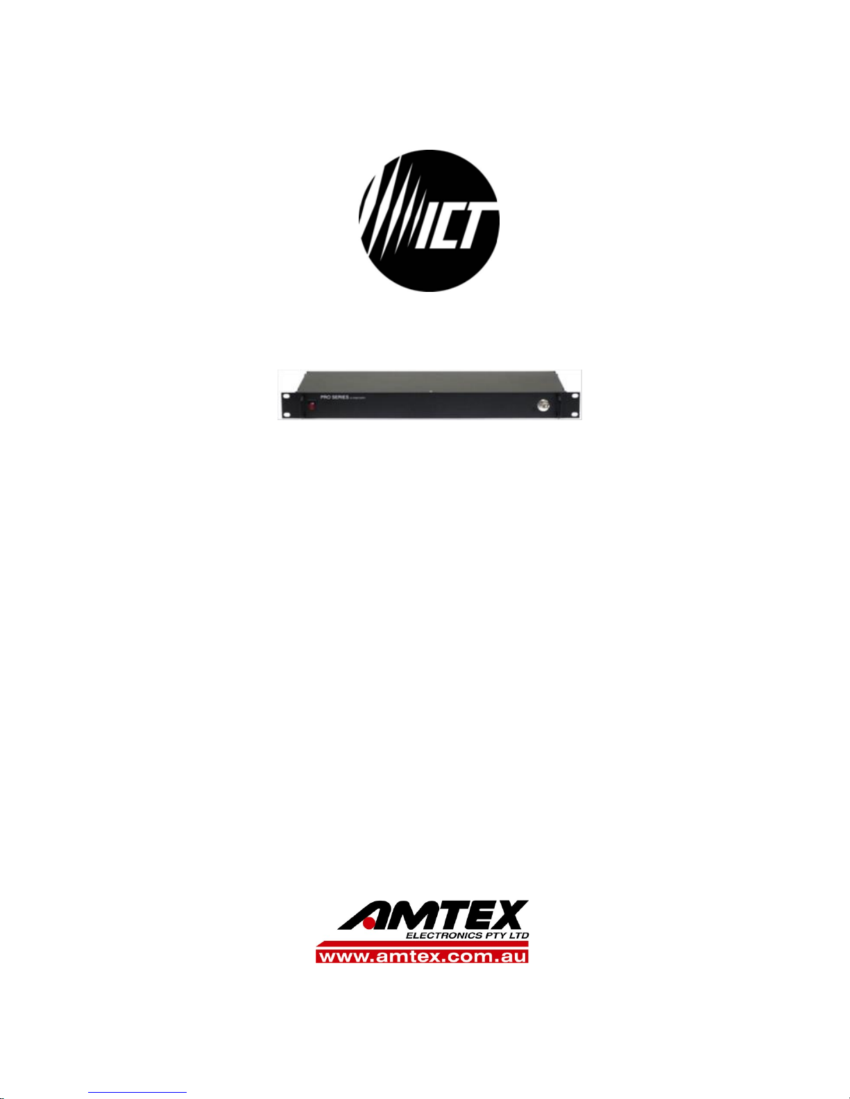
Pro Series DC Power
Supply
INSTRUCTION MANUAL
855-343-001
Models:
ICT690-12S/ICT690-12SB
ICT690-24S/ICT690-24SB
ICT690-48S/ICT690-48SB
ICT1190-12S/ICT1190-12SB
ICT1190-24S/ICT1190-24SB
ICT1190-48S/ICT1190-48SB
“DC Power Solutions…not just components”
Page 2

2 Innovative Circuit Technology Ltd.
WARNING
Risk of serious personal injury or damage to equipment and property! Always
observe the following:
Install and operate unit in a Restricted Access location, such as an enclosed
equipment rack
Operate the supply from a grounded 3-pin 120Vac or 230Vac outlet (50 or
60Hz) with a branch circuit breaker rated 20A or less
Always observe the following for applications requiring a back up battery:
Use only a Lead-Acid battery with rating and capacity appropriate for the
model of supply in use
Use an appropriate dc over-current protection device in line with the back-
up battery connection
Use a disconnect switch or circuit breaker in series with the battery
connection, to ensure installation and service is done with the battery de-
energised
Use wire and connectors rated for the maximum load current and size of
battery fuse or circuit breaker
Ensure battery polarity is correct before connecting
Do not attempt to charge a frozen battery
Handle batteries with care, never short circuit battery terminals
CAUTION
Risk of personal injury or damage to equipment! Always observe the following:
Install in a protected environment, keep sources of moisture away from unit
Ensure the total power consumption of the load does not exceed the
continuous rated capacity of the power supply output
Do not block air inlet or outlet openings in the unit
Do not place the power supply directly above or below an exposed battery,
due to possible presence of corrosive and/or flammable gasses
Do not add a ground connection to both battery and load, as this will bypass
the internal LVD relay
Page 3

Innovative Circuit Technology Ltd. 3
Table of Contents
INTRODUCTION ........................................................................................... 4
CHECK and CONFIGURE UNIT ..................................................................... 4
INSTALLATION ............................................................................................. 6
OPERATION ................................................................................................. 7
Status Indicators and Alarms .................................................................. 9
PRODUCT SPECIFICATIONS ....................................................................... 10
LIMITED WARRANTY ................................................................................. 12
Page 4

4 Innovative Circuit Technology Ltd.
INTRODUCTION
Pro Series power supplies from ICT provide a reliable 690 or 1200 Watts of rackmountable dc power with optional built-in battery back-up support and a low
voltage disconnect (LVD, option “B”) to power 12, 24, or 48Vdc based systems.
With an efficient wide range power factor corrected input the units are useable
world-wide, and their built in rack mounting ears and bus-bar outputs make
installation simple.
Wide range Power Factor corrected AC input supports operation world
wide
Dedicated independently controlled backup battery port with LVD relay
(units with LVD option “B”)
Selectable charge rates to accommodate lower capacity batteries (units
with LVD option “B”)
Remote on/off control input for external control of the output
Floating Form-C alarm contact output supports remote monitoring of
unit operation
Model1
Output
Voltage (V)
Max Output
Current (A)
Continuous
Current (A)
ICT690-12S(B)
13.8
50
50
ICT690-24S(B)
27.6
25
25
ICT690-48S(B)
55.2
12.5
12.5
ICT1190-12S(B)
13.8
100
87
ICT1190-24S(B)
27.6
50
44
ICT1190-48S(B)
55.2
25
22
CHECK and CONFIGURE UNIT
Perform a quick physical check of the unit as it is being taken out of the box to
ensure it has not been damaged during shipping. Check for the included parts
and accessories shipped with your unit:
5 pin Form-C alarm/remote connector plug (installed on unit)
Power cord (North America 120V 15A)
2 (3 for “B” units) ¼-20 Hex bolt, washer, nut sets for bus bar
connections
Output connector shield (installed over output bus bars)
Instruction Manual
1
Model suffix “B” denotes units equipped with the optional LVD Battery port
Page 5

Innovative Circuit Technology Ltd. 5
WARNING
Risk of serious personal injury or damage to equipment and property! Always
observe the following!
If a battery is used ensure the nominal battery voltage is correct for the
model of power supply, and that the battery positive is connected to the BAT
positive (+) terminal and the battery negative is connected to the NEG (-)
terminal.
Use an appropriate dc over-current protection device such as a fuse or
circuit breaker in line with the battery connection
Do not tie the POS and +BAT terminals together, as this will bypass the
internal LVD circuitry
Make any earth Ground connection to only a single LOAD or BAT terminal if
required. Do not ground both the load and battery as this may bypass the
internal LVD circuitry
AC input wiring to the Pro Series unit must be protected using an outlet with
a branch rated circuit breaker of 20A or lower value
Connection Diagram (Showing Rear Connectors and SW Switch 1-4)
Configure the Output Settings:
Always switch off the unit before changing the settings or making connections.
Choose a lead-acid battery with a nominal voltage rating (12/24/48V)
that matches the Pro Series rated output. Note that for good battery life
the battery should have a combined Ahr capacity of at least 3 times the
maximum charge current being used. (e.g. Use a 75Ahr or larger rated
battery (3 x 25A) with a 25A max charge setting)
Shown with battery backup/LVD, option B
Note: EARTH Ground connection may be made
to either load terminal
Page 6

6 Innovative Circuit Technology Ltd.
Set the max charge current to be supplied to the battery by setting SW
3, and SW 4 on the back panel according to the following chart: (note
that actual current flow to the battery may be less than the setting, and
is determined by the battery state of charge and temperature)
Max
Charge
(% of
Output)
Max
Charge
(100A
Models)
Max
Charge
(50A
Models)
Max
Charge
(25A
Models)
Max
Charge
(12A
Models)
BAT
SW3
Setting
BAT
SW4
Setting
100%
(Default)
100A
50A
25A
12.5A
1
1
75%
75A
38A
19A
9.4A 1 0
50%
50A
25A
12.5A
6.3A 0 1
25%
25A
12.5A
6.3A
3.1A 0 0
Maximum Charge Current – Switch Settings (1 = UP, 0 = Down)
Set the low voltage disconnect (LVD) disconnect and reconnect voltage
points, by setting SW 1, and SW 2 on the back panel according to the
following chart:
LVD Setting
12V
24V
48V
BAT SW1
Setting
BAT SW2
Setting
Disconnect V (Default)
11.5
23
46 x 1
Disconnect V (low setting)
10.5
21
42 x 0
Reconnect V (Default)
12.5
25
50 1 x
Reconnect V (low setting)
12
24
48 0 x
LVD Disconnect/Reconnect V – Switch Settings (1 = UP, 0 = Down, x = either)
INSTALLATION
Mount the unit in a standard 19 inch equipment rack, (ensuring side air vents are
not blocked) using rack mounting screws (not supplied), then make the following
connections using wire and connectors appropriately rated for the maximum
input and output current rating of the unit:
Remove the plastic bus bar cover by removing the two screws holding it in
place
Connect the supply POS output bus bar to the load positive input (using a
supplied bus bar bolt/washer/nut set for the bus bar connection) (NOTE: do
not connect the load directly to the battery, as this will defeat the battery
charging and low voltage disconnect functions)
Page 7

Innovative Circuit Technology Ltd. 7
Connect the supply NEG bus bar to the load negative input terminal (using a
supplied bus bar bolt/washer/nut set for the bus bar connection)
Connect a ground bonding wire from the chassis ground stud to the rack
On units with the optional battery back-up and LVD capability (model suffix
“B”):
o Choose a lead-acid battery with a float voltage rating that matches the
Pro Series output voltage, and has an Amp-hour (Ahr) capacity rating
greater than 3 times the max charge current setting of the power supply
(i.e. use a 75Ahr battery or larger on a 25A charge setting)
o Connect the battery negative to the supply NEG bus bar
o Connect the battery positive to an over current protection device (fuse
or breaker) and disconnect switch
o With the battery fuse removed or disconnect switch open connect the
fuse or switch to the supply BAT(+) terminal
o Either the POS or NEG load lead may be connected to earth ground if
required, but the internal LVD contactor is always connected to the
battery positive, as shown. NOTE: Do not ground the battery POS
terminal, as this may bypass the internal LVD relay
Connect the remote on-off control or unit form-C alarm contact monitoring
wiring to the REMOTE connector if needed, as shown in the following table:
Pin Number
Name
Function
1
Shutdown (+)
Remote output shutdown, positive
(2.5-16Vdc)
2
Shutdown (-)
Remote output shutdown, return
3
NC
Alarm NC (alarm state)
4
NO
Alarm NO (alarm state)
5
Common
Alarm output common
REMOTE Connector: (use 22-26AWG wire)
Check that all connections to the power supply are correct and tight; re-install
the plastic bus bar cover using the original two screws provided.
Connect the AC power cord: Plug an approved AC power cord set rated for 15A
(120V) or 10A (230V) into the IEC type AC input connector on the back panel of
the supply (120V cord included with unit), then plug into a grounded 3 terminal
120Vac or 230Vac power outlet, with the front panel switch in the off position.
OPERATION
Switch on the unit using the front panel power switch, and observe that the front
panel green POWER LED is lit. Verify the supply output voltage using a hand held
Page 8

8 Innovative Circuit Technology Ltd.
digital voltmeter. If a battery is connected install the external fuse and close the
disconnect switch.
On units with the battery back-up option connected switch off the ac power, and
use a hand held digital voltmeter to verify that the battery voltage is provided to
the output load terminal. Switch AC power back on, and verify the output supply
voltage rises to the normal output rating as the battery charges.
The unit can now be left operating normally. As long as the external back-up
battery voltage is greater than the low voltage disconnect (LVD) level the battery
will be connected directly to the supply output and will instantly power the load
in case of an AC power failure. With AC power off the battery will then gradually
be discharged by the load. When the battery voltage drops below the LVD
disconnect level the internal relay will open, preventing the battery from being
excessively discharged.
When AC power returns the supply will close the LVD relay and charge the
battery to bring the voltage back up to the float voltage level. Battery charge
current is limited to the maximum rate determined by the charge current setting
of SW 3 and 4 (see table on page 5), while the output voltage will be determined
by the battery state of charge, and will rise to the output float voltage over time.
The battery will be maintained at the supply output (float) voltage level until AC
power is removed.
Batteries connected directly to the supply output (not using the LVD option BAT
terminal) will be charged to the supply output voltage level with a current limited
to the maximum supply output rating.
The remote shutdown input may be used to disable the supply output by
applying a voltage from 2.5 to 16V, and the form-C alarm contacts can be used to
remotely monitor fault conditions per the Status Indicators and Alarms table.
PARALLEL OPERATION
Up to 3 matching units without the optional battery backup capability may be
connected in parallel to power higher current loads. The unit with the highest
output voltage will initially provide most of the load current, and as load current
increases the current supplied will tend to balance between the parallel units.
CAUTION
Risk of damage to equipment!
Ensure battery current supplied through the optional internal LVD contactor
cannot exceed the current rating of the unit
Do not use the internal LVD contactor for parallel applications where load
current can exceed the maximum rating of a single unit
Page 9

Innovative Circuit Technology Ltd. 9
Status Indicators and Alarms
The 2 LEDs on the front panel and the Form-C alarm contacts on the back
indicate the status of the power supply:
Alarm or
Notification
Trigger Condition
LOAD
Output
BATT
LVD
Red
FAULT
LED
Green
POWER
LED
Input AC OK,
battery charging
Normal operation,
battery charging
Enabled
Enabled
-
ON
Input AC OK,
battery charged
Normal operation,
battery charged
Enabled
Enabled
-
ON
AC Undervoltage Warning
Triggers when Input
Voltage drops below
approx. 90Vac
Enabled
Enabled
ON
ON
AC Fail
AC fails or front switch
is off (Battery above
LVD level)
Battery
power
only
Enabled
ON
-
Battery Low
(when AC Off)
Triggers when battery
voltage falls below the
LVD threshold
OFF
OFF
ON
-
System Fault
Indicates internal
circuit fault - Clears
when all fault
conditions are cleared.
Battery
power
only
Enabled
ON
-
Dead or
Disconnected
Battery (AC
present)
Battery voltage is less
than 5/10/20V (on
12/24/48V models)
No charging
Enabled
OFF
-
ON
Battery Over
Voltage Fault
(AC present)
Triggers when the
battery voltage
exceeds the internal
OVP threshold for 3s
Enabled
OFF
ON
ON
DC Overvoltage
Shutdown
Triggers for output
voltage above
16.5/33/66VDC for 1s.
Clears when Input
power cycled off/on
Battery
power
only
Enabled
ON
-
Overtemperature
Shutdown
Triggers when internal
temperature is too
high. Clears when
back to normal range.
Battery
Power
only
Enabled
ON
-
The form-C alarm contact will be triggered for any condition that lights the red
FAULT LED, or shuts down the output of the unit.
Page 10

10 Innovative Circuit Technology Ltd.
PRODUCT SPECIFICATIONS
AC Input (IEC C 14 connector): 110 to 254Vac 50/60Hz
Input Power Factor: 0.99 typ (120Vac input)
Peak Efficiency (typical): 90%
Output V Line Regulation: +/- 0.1%
Output V Load Regulation: +/- 1%
Model:
12V
100A
12V
50A
24V
50A
24V
25A
48V
25A
48V
12.5A
Output Voltage 2 (Nominal
Battery float Voltage) (+/-
0.5%)
13.8V
13.8V
27.6V
27.6V
55.2V
55.2V
Max Current Limit
(+5%, -0%)
100A
50A
50A
25A
25A
12.5A
Continuous Current Rating
87A
50A
44A
25A
22A
12.5A
Output Power (max) 3
1200W
690W
1200W
690W
1200W
690W
Output Noise (max mVrms)
30
30
30
30
40
40
Input Current (max at
120Vac)
12A
7A
12A
7A
12A
7A
LVD Threshold V (Default)
11.5V
11.5V
23.0V
23.0V
46.0V
46.0V
LVD Reconnect V (Default)
12.5V
12.5V
25.0V
25.0V
50.0V
50.0V
Output Grounding: Floating, may be
connected with Positive or
Negative ground
Alarm Output: Form-C contact, 0.5A
60Vdc max
Remote Shutdown: 2.5 to 16V signal to disable
output
DC Connectors: (Output, Battery) Bus Bar, 5/16” bolt hole
2
Actual Operating point may be lower due to battery charge requirement
3
Output power will be limited to approximately 1080W when operating with AC input voltage less
than 110Vac
Page 11

Innovative Circuit Technology Ltd. 11
Alarm, on/off Connector: 5 pin removable plug, cage
clamp type 16 –24 AWG
Operating Temperature Range: -30C to +60°C4
Storage Temperature Range: -40 to +70°C
Humidity: (Operating) 10 – 90% (non-condensing)
(Storage) 5 – 95% (non-condensing)
Cooling: Temperature controlled
fan
Regulatory Compliance: Designed to meet
UL/CSA60950-1, Meets
FCC Part 15 Class B limits
Dimensions (inches):
Weight: 7.5lbs/3.4kg
EMC Note: This equipment has been tested and found to comply with the limits for a Class
B digital device, pursuant to part 15 of the FCC Rules and ICES 003. These limits are
designed to provide reasonable protection against harmful interference in a residential
installation. This equipment generates uses and can radiate radio frequency energy and, if
not installed and used in accordance with the instructions, may cause harmful
interference to radio communications. However, there is no guarantee that interference
will not occur in a particular installation. If this equipment does cause harmful
interference to radio or television reception, which can be determined by turning the
equipment off and on, the user is encouraged to try to correct the interference by one or
more of the following measures:
Reorient or relocate the receiving antenna.
Increase the separation between the equipment and receiver.
Connect the equipment into an outlet on a circuit different from that to which
the receiver is connected.
Consult the dealer or an experienced RF technician for help.
4
De-rate output 2% per °C above 50°C
Page 12

LIMITED WARRANTY
ICT Ltd. warrants to the original consumer purchaser that this product shall be in
good working order, free from defects in materials and workmanship, for a
period of three (3) years from the date of purchase. Should failure occur during
the above stated time period, then ICT will, at its option, repair or replace this
product at no additional charge except as set forth below. All parts, whether for
repair or replacement, will be furnished on an exchange basis. All exchange
pieces become the property of ICT. This limited warranty shall not apply if the ICT
product has been damaged by unreasonable use, accident, negligence, disaster,
service, or modification by anyone other than the ICT factory.
Limited warranty service is obtained by delivering the product during the above
stated three (3) year warranty period to an authorized ICT dealer or ICT factory
and providing proof of purchase date. If this product is delivered by mail, you will
insure the product or assume risk of loss or damage in transit, and prepay
shipping charges to the factory.
Every reasonable effort has been made to ensure that ICT product manuals and
promotional materials accurately describe ICT product specifications and
capabilities at the time of publication. However, because of ongoing
improvements and updating of ICT products, ICT cannot guarantee the accuracy
of printed materials after the date of publication and disclaims liability for
changes, errors or omissions.
If this ICT product is not in good working order, as outlined in the above
warranty, your sole remedy shall be repair or replacement as provided above. In
no event will ICT be liable for any damages resulting from the use of or the
inability to use the ICT product, even if an ICT employee or an authorized ICT
dealer has been advised of the possibility of such damages, or for any claim by
any other party.
ICT reserves the right to make changes without further notice to any products or
documentation for improvement of reliability, function, or design.
ICT Ltd. does not recommend use of its products in life support applications
wherein a failure or malfunction of the product may directly or indirectly
threaten life or cause injury. The user of ICT products, which are to be used in life
support applications as described above, assumes all risks of such use and
indemnifies ICT against all damages.
INNOVATIVE CIRCUIT TECHNOLOGY LTD.
 Loading...