

Page 1

1
Page 2

2
Contents
1. General Information ................................................................................................................ 4
1.1. Features ................................................................................................................ 4
1.2. System Specifications ........................................................................................... 5
1.3. Dimensions ........................................................................................................... 7
1.4. Module Descriptions .............................................................................................. 8
2. Installation ............................................................................................................................ 10
3. Operation .............................................................................................................................. 12
3.1. EZ code overview ................................................................................................ 12
3.2. Dispensing Coins To Low Level........................................................................... 14
3.3. Operating Function Descriptions ......................................................................... 15
3.4. Setting Function Descriptions .............................................................................. 18
3.5. Executive Setting Function Descriptions ............................................................. 39
3.6. DIP Switch Setting............................................................................................... 47
4. Harness Application .............................................................................................................. 48
4.1. List of Main Wire Harness: ............................................................................... 48
4.2. List of Wire Harness for ICT Bill Acceptor: ....................................................... 48
4.3. Wire Harness Pin Assignment for JPSTD interface ............................................. 49
4.4. Wire Harness Pin Assignment for MDB interface ................................................ 53
4.5. Wire Harness Pin Assignment for Executive & MDB Interface ............................ 57
4.6. Wire Harness Pin Assignment for Download Box ................................................ 59
5. I/O Circuit.............................................................................................................................. 60
6. Maintenance ......................................................................................................................... 63
7. Troubleshooting .................................................................................................................... 65
7.1. Error Code Messages ......................................................................................... 65
7.2. Error Handling ..................................................................................................... 66
8. Firmware Download and Upgrade Instruction ....................................................................... 80
8.1. MCU STM32 Firmware Download by FP-004 ..................................................... 80
8.2. MCU STM32 Firmware Download by IrDA Special Function ........................... 83
9. PC Tool Instruction................................................................................................................ 84
9.1. Cashfloat Setting ................................................................................................. 84
9.2. Serial Number Setting ......................................................................................... 89
10. Read Audit Data ........................................................................................................... 90
10.1. Read Audit Data by ICT MTB .............................................................................. 90
10.2. Read Audit Data by IrDA ..................................................................................... 91
11. Module Assembling Procedure .................................................................................... 92
11.1. Upper Module Disassembling: ............................................................................ 92
11.2. Recognition Module Disassembling: ................................................................... 93
11.3. Coin Discharge Module Disassembling: .............................................................. 94
12. Module Exploded Views ............................................................................................... 95
Page 3

3
Use of Materials Limitations
International Currency Technologies Corporation (ICT) all rights reserved.
All materials contained are the copyrighted property of ICT.
All trademarks, service marks, and trade names are proprietary to ICT.
ICT reserves the right at all times to disclose or to modify any information as
ICT deems necessary to satisfy any applicable law, regulation, legal process
or governmental request, or to edit, refuse to post or to remove any information
or materials, in whole or in part, in ICT's sole discretion.
Page 4

4
1.
General Information
1.1. Features
z Six tube cassette for maximum coin inventory.
z Easy to use and suitable for vending machines world wide.
z LCM display shows current coin changer status.
z Optional portable programmer to update coin changers installed on
vending machines.
z Modular design for cheap and easy maintenance.
z Modular tubes for a variety of coin configuration.
z Adjustable acceptance rate calibration on site.
z High security through state of the art anti-fishing mechanism.
Page 5

5
1.2. System Specifications
Supply Voltage MDB: 20V DC ~ 45V DC
MDB: 10V DC ~ 45V DC (Battery Mode)
JPSTD: 24V DC ±10%
Executive: 24V AC ±10%
Power Consumption Standby mode ≦ 3.6W
Coin acceptance ≦ 15.6W
Coin payout ≦ 15.6W
(36W max. when Power is turned on
initially)
Battery operation (Power Saving Type)
Sleep mode
≦
10uA
Standby mode
≦
3.6W(wake-up mode)
Temperature Range -15°C ~ +60°C
Storage Temperature -30°C ~ +70°C
Temperature Change Max. 0.2°C / minute
Relative Humidity Up to 85% (no condensation)
Serial Interface MDB (connector: Minifit 6-pin)
JPSTD
Executive (connector: Molex 15-pin & 9pin) 1)
Peripherals MDB MDB Bill Acceptor
(for MDB & Executive interface)
MDB cashless key reader
(for Executive interface only)
ICT MTB (Multi Tool Box)
Display LCM
Menu language:
English, Русский,
Deutsch, Español, Français, Português
Italiano
1
In some models interface is selected by DIP Switch or automatically.
Page 6

6
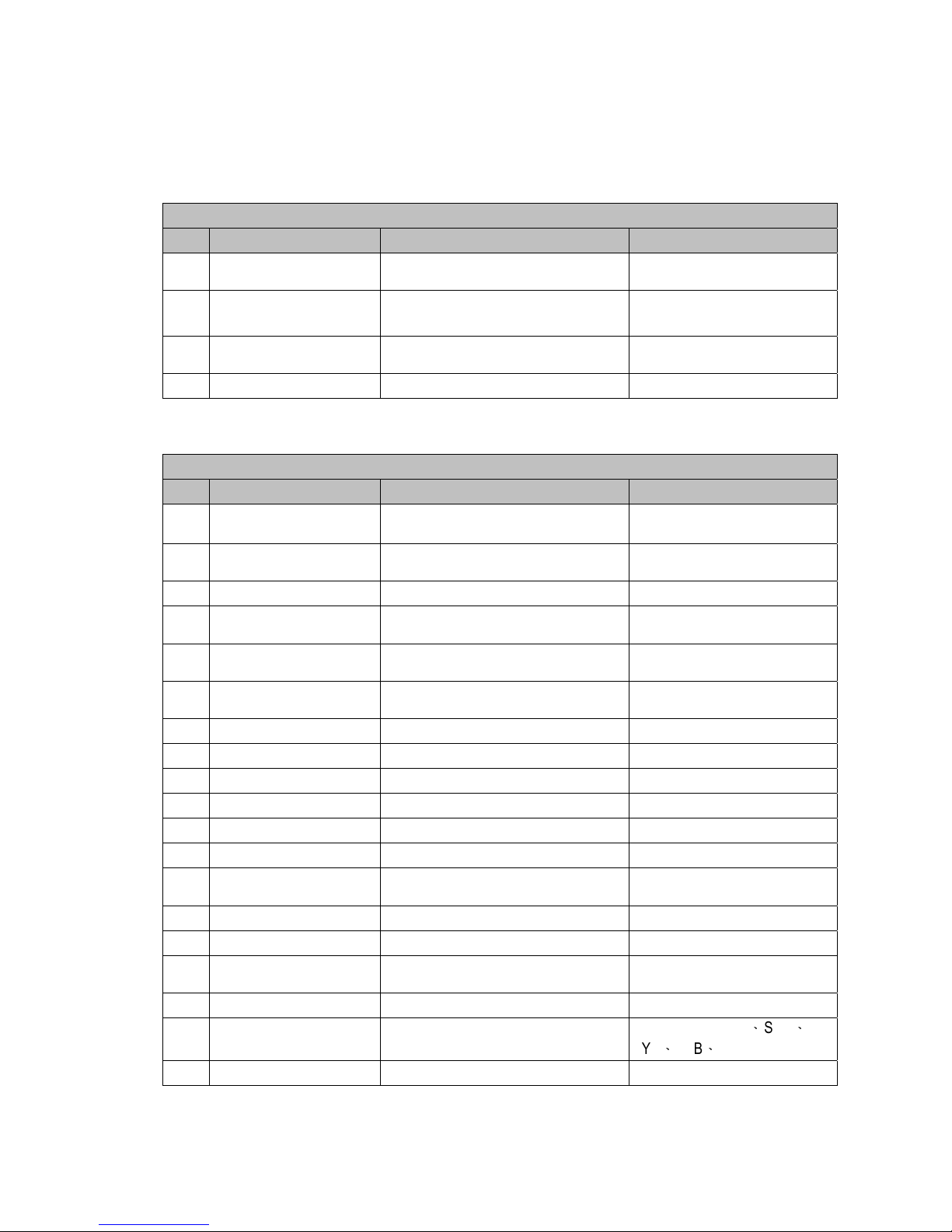
Acceptable Coin Size Coin diameter 16mm ~ 28mm
Coin Thickness 1.2mm ~ 3.2mm
Acceptance Speed Approx. 1 coin / second
Coin payout Max. 6 coin types from a tube cassette
Coin diameter and thickness for dispensing depends on tube cassette type in use
TUBE
Coin Diameter mm
A B C D E F
26.0 - 28.0
v , * v , *
- - - -
26.0 - 26.5
V V
- V V -
24.0 - 26.0
v , * v , *
v V v v
22.0 - 24.0
v , *
V
v v v v
20.0 - 22.0
V V
v v v v
18.0 - 20.0
V V
v v v v
16.0 - 18.0
- -
v v v v
(* Supports Escrow Function)
Other Functions Downloadable audit - EVA-DTS by IrDA
or UART (for MDB & Executive)
Firmware Updates by IrDA (for MDB &
Executive)
MDB-FTL (only for MDB Interface)
Customer & Product Serial Number
Setting
99 coin channels
Colored diagnostic LEDs
Page 7

7
1.3. Dimensions
Unit : mm
Mounting position:
Vertical, max. deviation: ± 3°
Mark of conformity: CE、FCC
Page 8
8
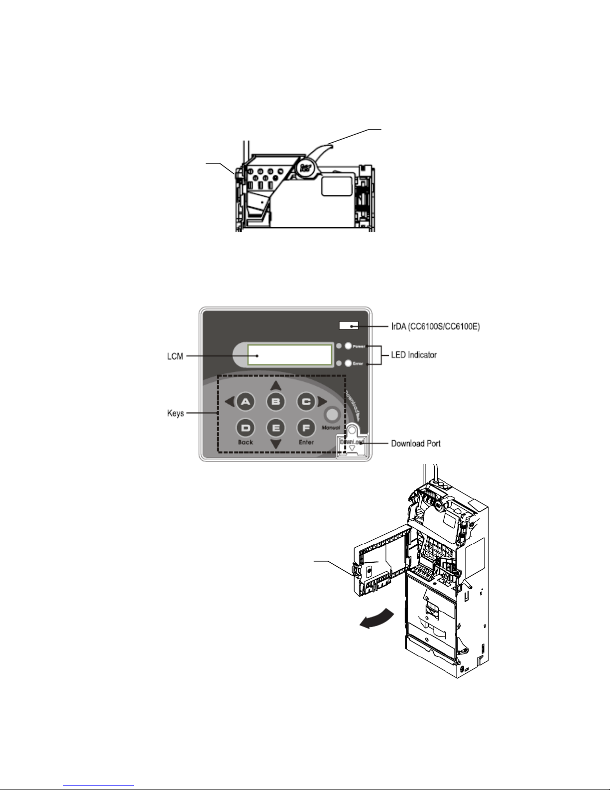
1.4. Module Descriptions
Recognition: As shown in figure below
Coin Return Lever: After a coin is inserted, press the coin return button to return the
coin
LCM Panel: As shown in figure below
To open the LCM panel, press the latch to open.
Coin Return Lever
Hook
Latch
7 Panel
Buttons
Page 9
9
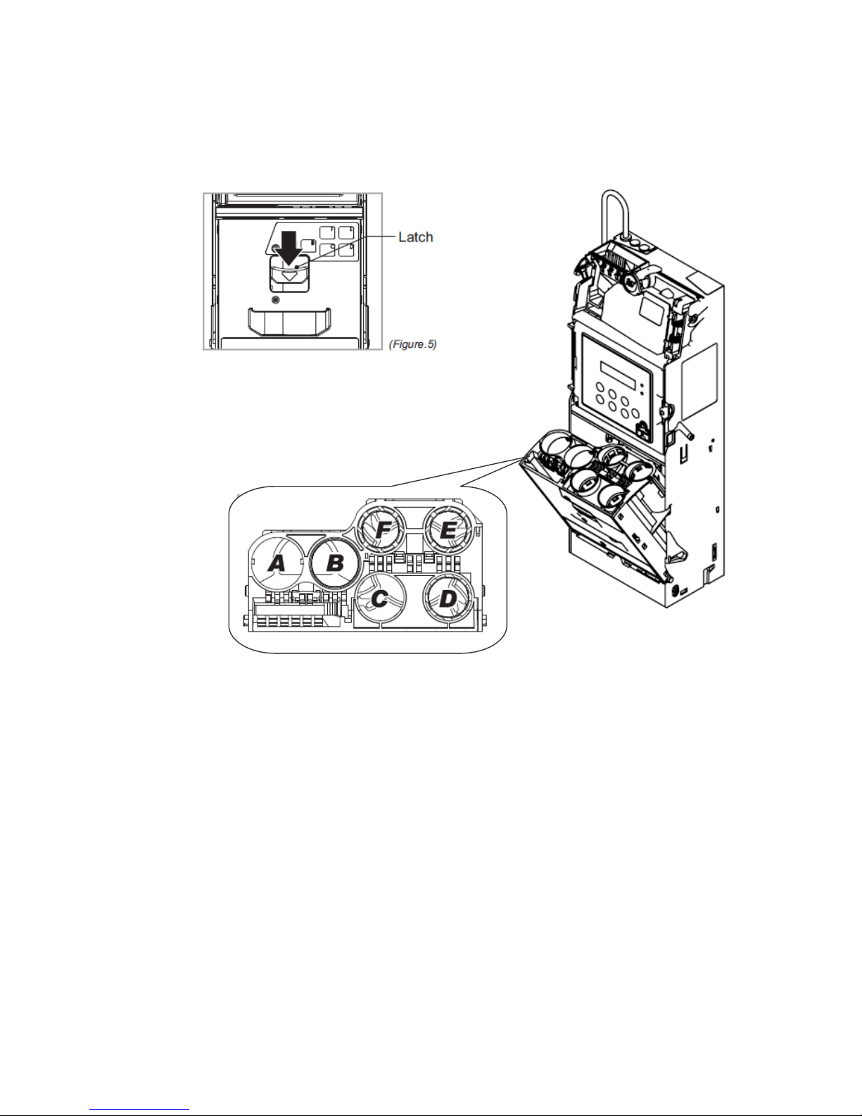
Coin Tubes: Press the latch as shown below to remove the coin cassette
Page 10
10
2.
Installation
Attention!! Prior installation, please remove the coin changer from the carton
and inspect for damages.
Attention!! Turn off VMC Power during installation – IMPORTANT!!!
Warning!! Do not plug both MDB and Executive connector to VMC board
simultaneously!! It may cause damage of VMC board.
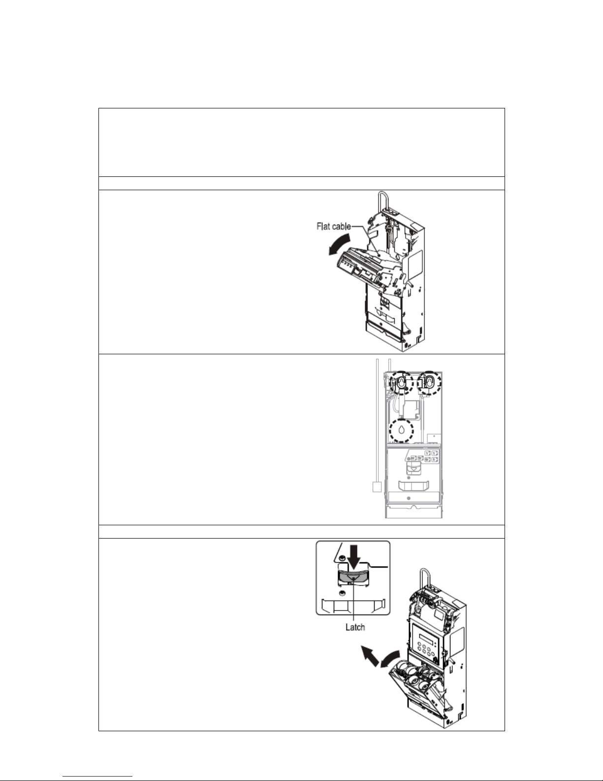
Device Mounting Instruction
1. Press the green hook at the left side of the
coin changer and tilt the upper module.
2. Unplug flat cable to separate upper module
from device.
3. Loosen the 3 mounting screws 2 or 3 turns.
(do not unscrew these completely)
Lift the coin changer to mount inside the vending
machine.
4. Tighten the screws and place the upper
module back to the device.
5. Plug flat cable back to upper module then
close the upper module until it has been firmly
fixed by the green hook.
Plug device power and communication cable to
vending machine.
Tube Cassette Refill Instruction
6. Press the green cassette fixed latch to pull out
the cassette at an upwardly slanted angle.
7. Refill coins into tube cassette and ensure that
the coins enter the corresponding tubes and flatly
placed. Then place the tube cassette back to
Changer.
Note! You may choose coin refill mode to refill
coins without open tube cassette. (Refer to
code 100)
Page 11
11
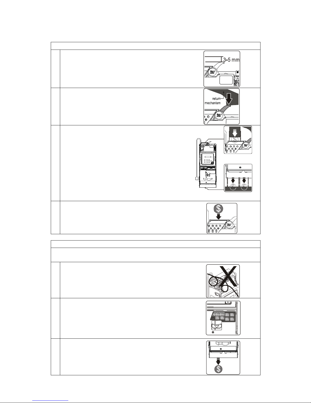
Installation Checklist
Check that there is a 3 to 5 mm gap between the coin changer
return lever and the vending machine return mechanism.
Check that when vending machine return lever has been pressed
and released, the reject gate of the coin recognition module can
be opened and closed properly.
Check that the coin insertion, coin return box, and coin storage
box channels of the vending machine line up with the
corresponding slots of the coin changer. If the slot has not been
lined up, please adjust accordingly.
Insert a coin to check whether it can pass through the coin
changer successfully. Please ensure that there is no interference
around the coin recognition module.
Initialization Checklist
While vending machine in an energized state, please DO NOT plug/unplug any
wires on CC6100.
Please ensure that there are no interferences between the
connected wires, the coin insert and return device, and the door
of the automatic vending machine. After the inspections are
complete, then turn on the vending machine power.
Check the amount of coins in each coin tube is above the
minimum requirement level. Please refer to sticker on the tube
cassette for minimum level information.
(The coin changer would not work correctly without enough coins
in the coin tubes.)
After refill of tube cassette, the coin changer will detect the
adequate coin quantity within a few seconds.
Dispense at least 1 coin from each coin tube to ensure that the
dispensed coins fall into the coin return box of the vending
machine.
Page 12
12
3.
Operation
3.1. EZ code overview
Operating Functions
Code LCM Display Function Description
100 Refill Coin
Coin Refill Function by Coin Insertion
under Cash Float Mode
-
A
ccessible without password
-Cash Float Mode only
101 Total In/Out
Check the Total Coin PayIn and PayOut
Value Counter
-Accessible without password
115 Clear Tube Count
Clear Counting Memory of All Coin Tube
Inventory
-Accessible without password
129 Language Set language -Accessible without password
To access all menu functions requires password verification. Press “D” 3 times under main menu to open
password input page. Default Password is ABCD. See next page for complete menu functions.
Setting Functions
Code LCM Display Function Description
102 Reset Records
Clear the Total Coin PayIn and PayOut
Value Record
103 Accept/Reject Coin Switch
Set
A
ccept or Reject to Coin
Denominations
104 Tube Open/Close Switch Set Open or Close to Coin Tubes
107 Configure Cash Float
Set Cash Float Configuration for Various
Coin Denominations
-Cash Float Mode only
108 Activate Cash Float
Set Cash Float Type for Various Coin
Denominations
-Cash Float Mode only
109 Check Current Cash Float
Check Current Cash Float of Various
Coin Denominations
-Cash Float Mode only
110 Change Mgmt. Set the Change Return Mode
111 Idle Display Set the Standby LCM Display Mode
112 BA Type Setting Set the BA Interface
113 Default Setting Restore to Default Factory Settings
116 Cassette Type Coin Tube Configuration Mode -Special Function
117 Error Info Display Error Message Records
118 Bill(s) per Transaction
Set the Bill Acceptance Limitation for the
BA
-ICT BA only
119 CashFloat Mode Set Coin Tube Inventory Counting Mode
120 Set ID Set Customer & Machine Number
121 Coin->CashBox Setting
Set Coin Acceptance to Cash Box
Condition
122 Expansion Escrow Setting Set Escrow for NTD 50 -Special Function, only for NTD
123
Sensor Inventory
Adjustment
Detect Tube Inventory
-Only MDB for TWD
、
SGD
、
MYR、THB、CNY
124 Reserved Coin Set Reserved Coin Function
Page 13
13
Code LCM Display Function Description
125 Accessibility options
Set LCM accessibility under door-switch
status and password security
126
Manual Inventory
Adjustment
Refill Coin Inventory function by inserting
coins into tube cassette directly
-Only MDB for TWD
、
SGD
、
MYR、THB、CNY
127 Residual Credit
Setup residual credit, price adjusted by
Changer
128 Token Learning Mode Token learning mode -For MDB & Executive
130 Reject Lever Setting Set no refund after inserting payment -For MDB & Executive
131
A
cceptance limit For
Changer
Set Credit Acceptance Limit -Only MDB for KRW
132 Maximum for Insert Q'TY
Set limitation of coins in single
transaction
-Only MDB for KRW
133 Decimal and Scaling Set Decimal point and Scaling Factor -For MDB & Executive
134 Currency Code Setting Currency Code
135 Error Report Setting Error Report Function
136 Payout Method
Setting Payout Method
(
Level 2)
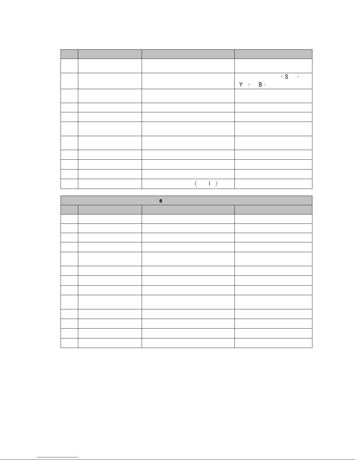
Executive Setting Functions
Code LCM Display Function Description
200 Sell Mode Set Single Vend or Multi Vend -Executive only
201 Price Display Set Price Display on VMC -Executive only
202 Product Price Set Product Price Holding by Changer -Executive only
203 Price Holding Set Price Holding by Changer or VMC -Executive only
204 2nd Price for Cashless
Set 2
nd
price for cashless function on or
off
-Executive only
205 Enable Bill Acceptor Set BA enable with or without e-key -Executive only
206 Decimal Adjustment Decimal Setting -Executive only
207 Residual Credit Setup residual credit -Executive only
208
A
cceptance limit For
Changer
Set Credit Acceptance Limit -Executive only
209 Credit limit For Cashless Set Credit limit for cashless
-Executive only
210 Bill(s) per Transaction Set BA limitation per transaction -Executive only
211 Exact Change Notice Set exact change notice on display
-Executive only
212 Exchange Rate Set Exchange Rate -Executive only
Page 14
14
3.2. Dispensing Coins To Low Level
Dispensing coins to low level in all coin tubes
* Press the return lever together with manual button for 3 seconds. Changer will
discharge coins until all tubes reach one under minimum level.
(If the minimum level has not been configured by the user, the default minimum coin
level would be applied.)
Dispensing coins to low level in a specific tube
* Press tube key once to dispense 1 coin from corresponding tube.
* Press the return lever together with the tube key for 3 seconds. Changer will discharge
the selected tube until it reaches one under minimum level.
Page 15
15
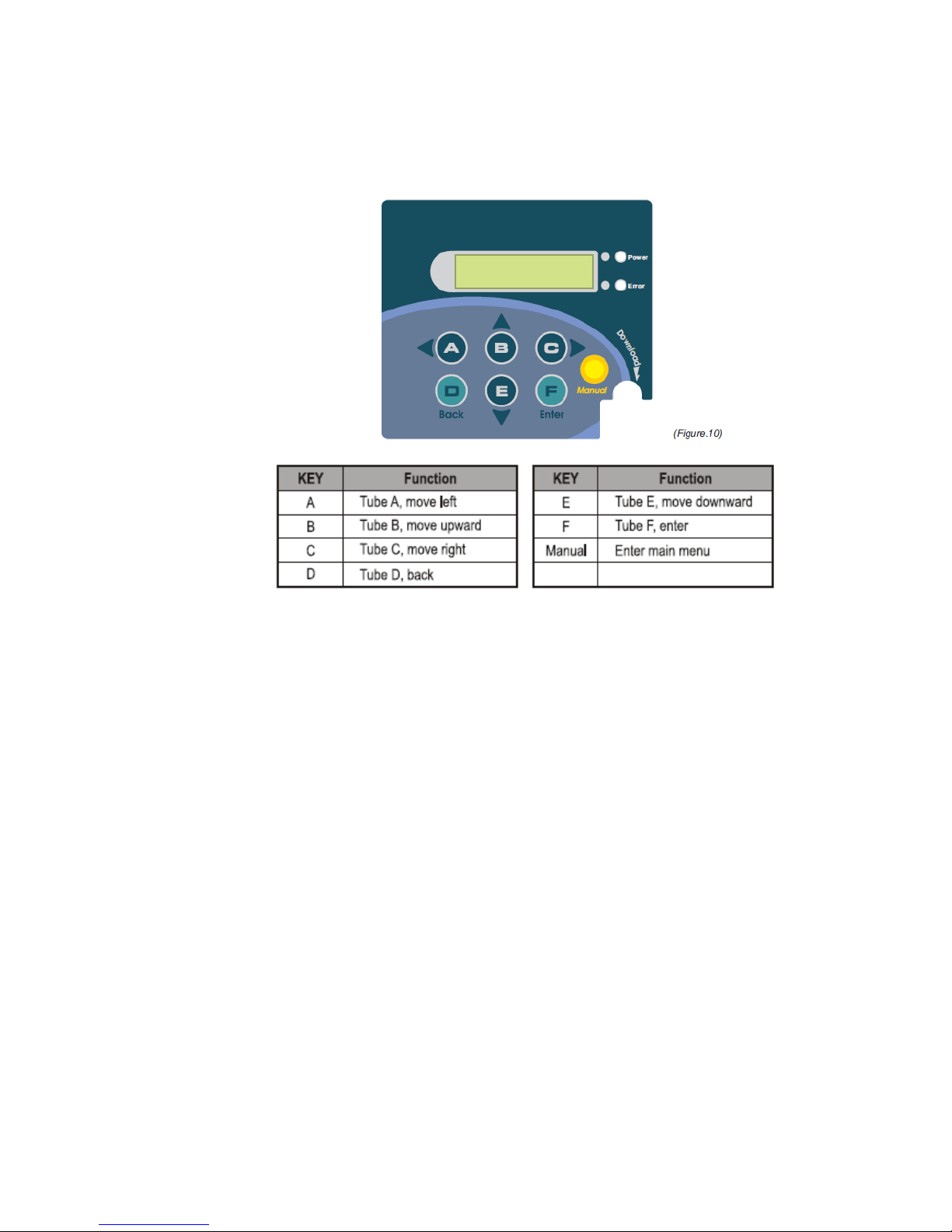
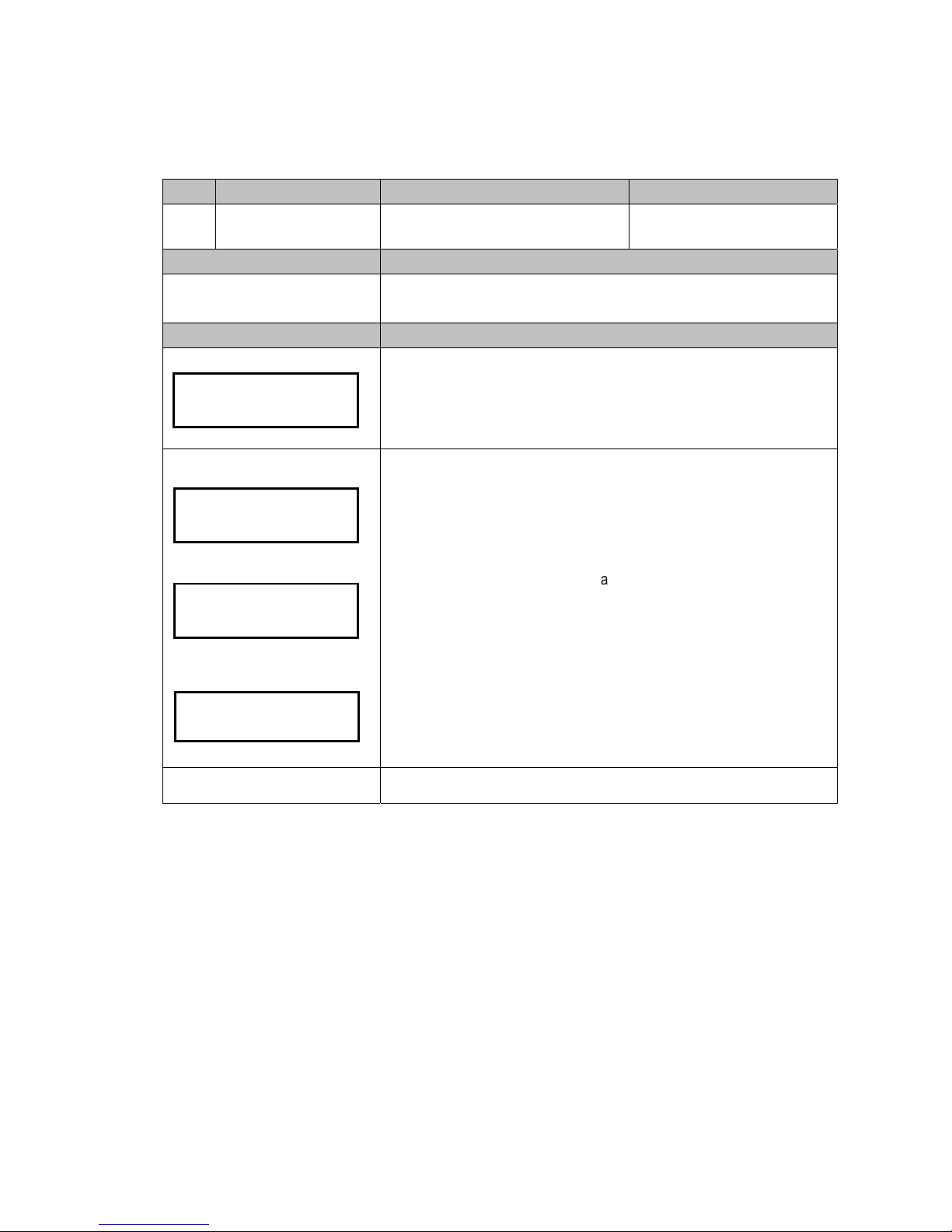
3.3. Operating Function Descriptions
Code LCM Display Function Description Accessibility
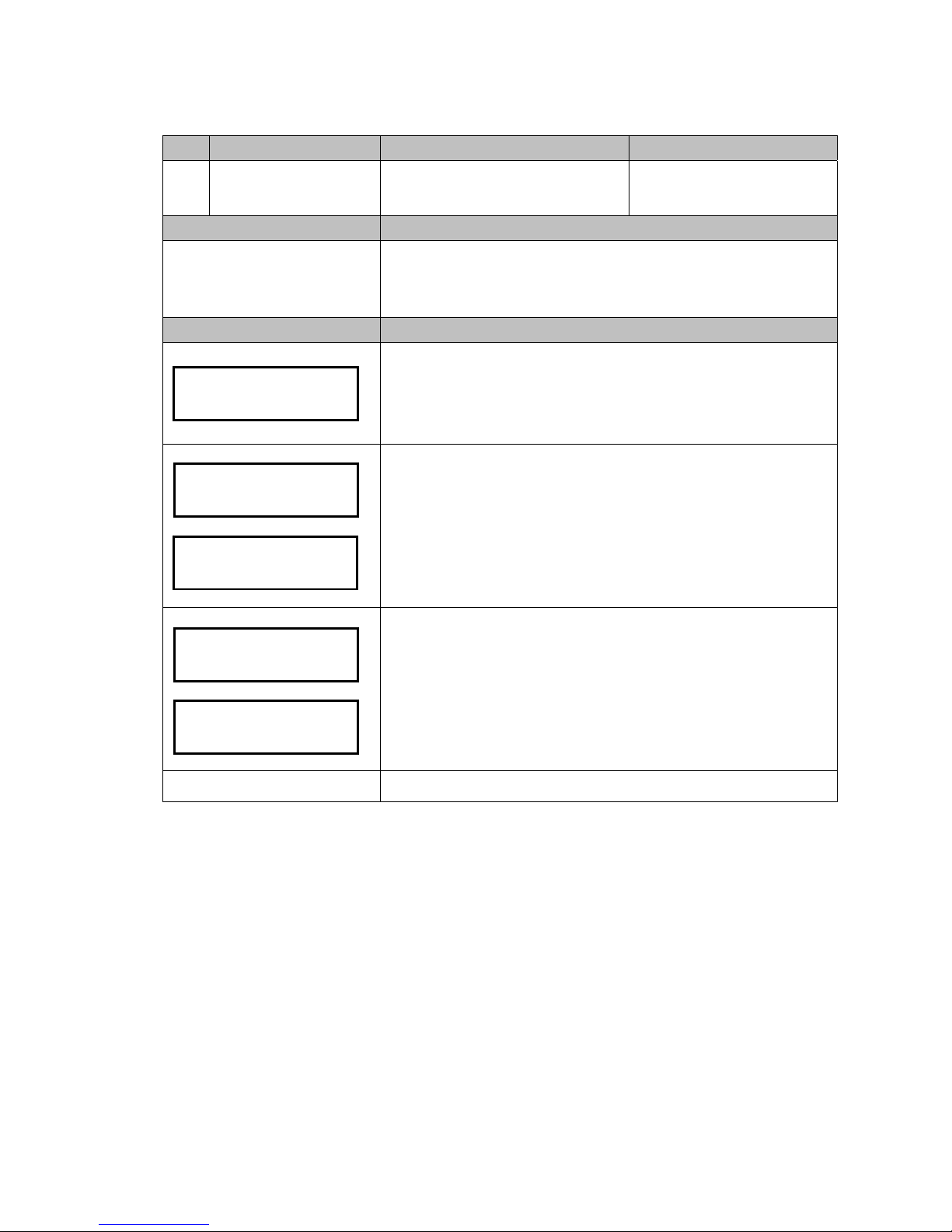
100
Refill Coin
Coin Refill Function by Coin Insertion
under Cash Float Mode
-Accessible without password
-Cash Float Mode only
Default Definition
N/A
Enter coin refilling mode to fill up to cash float level of each coin tube.
Note! Cash float level depends on code 107 setting.(see 3-2-3)
LCM Descriptions
Press the Manual button.
Use A / C to scroll to EZ code 100.
Press F to enter.
Positions
Require amount
Number disappears when tube
reach cash float level
LCM shows required amount of each denomination in sequence from low to
high value, as left figure position A to F.
In example of EU 6 denominations, position A to F represent denominations
of 5cent, 10cent, 20cent, 50cent, 1
€
and 2€.
Insert coins until all tubes reach cash float level.
The counter decreases when refilling coins and disappears when it reaches
cash float level.
Caution!! Please empty all coin tubes before refilling, and do not
repeatedly enter the refill mode among refilling.
Manual to exit.
- A,- B,- C
- D,- E,- F
Refill Coin
100
- 70,- 61,- 55
- 49,- 50,- 53
- 40,- 32,-
-
-
Page 16
16
Code LCM Display Function Description Accessibility
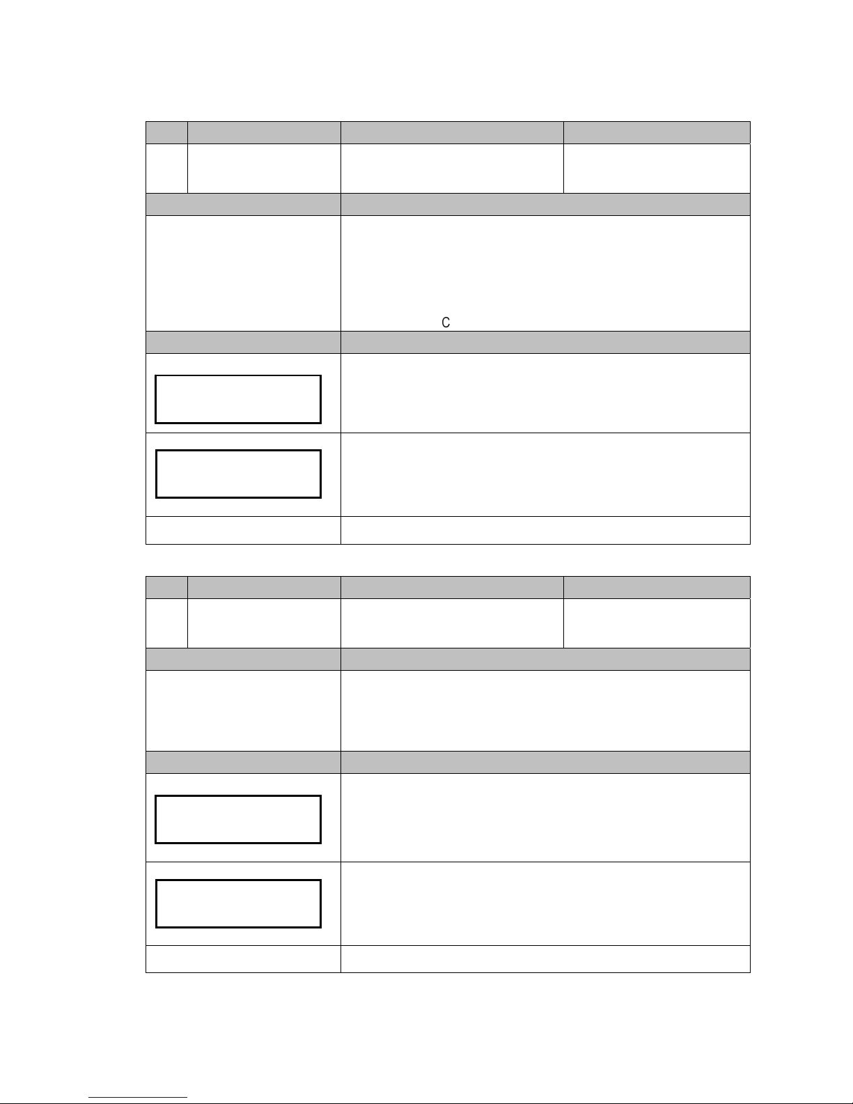
101
Total In/Out
Check the Total Coin PayIn and PayOut
Value Counter
-Accessible without password
Default Definition
N/A Display current bookkeeping data.
LCM Descriptions
Press the Manual button.
Use A / C to scroll to EZ code 101.
Press F to enter.
Use B / E to switch the data below:
-Pay in amount
-Pay out amount
-Difference ( IN>OUT display “+”, OUT>IN display “-”)
Press Manual to exit.
Manual to exit.
Code LCM Display Function Description Accessibility
115
Clear Tube Count
Clear Counting Memory of All Coin Tube
Inventory
-Accessible without password
Default Definition
N/A Clear tube inventory counter’s memory.
LCM Descriptions
Press the Manual button.
Use A / C to scroll to EZ code 115.
Press F to enter.
Press F to clear memory..
Caution!! Please empty the coin tubes before clear memory. Leave
coins inside tube cassette may cause operational problem to changer.
Manual to exit.
Total In/Out
101
PayIn : $0
PayOut: $0
Difference:
$0
Clear Tube Count
Clear Tube Count
Are You Sure?
Page 17
17
Code LCM Display Function Description Accessibility
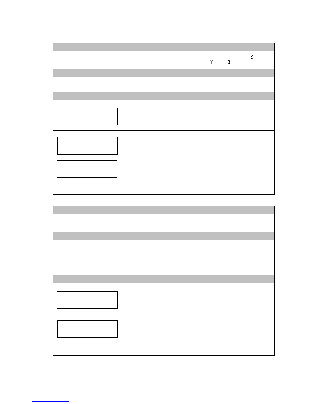
129
Language Set language
-Accessible without password
Default Definition
Depends on region
User can select menu language.
-English
-Русский
-Deutsch
-Español
LCM Descriptions
Press the Manual button.
Use A / C to scroll to EZ code 129.
Press F to enter.
LCM shows current setting.
Press B / E button to select language.
Press F to save.
Manual to exit.
English
Language
129
Page 18
18
3.4. Setting Function Descriptions
Code LCM Display Function Description Accessibility
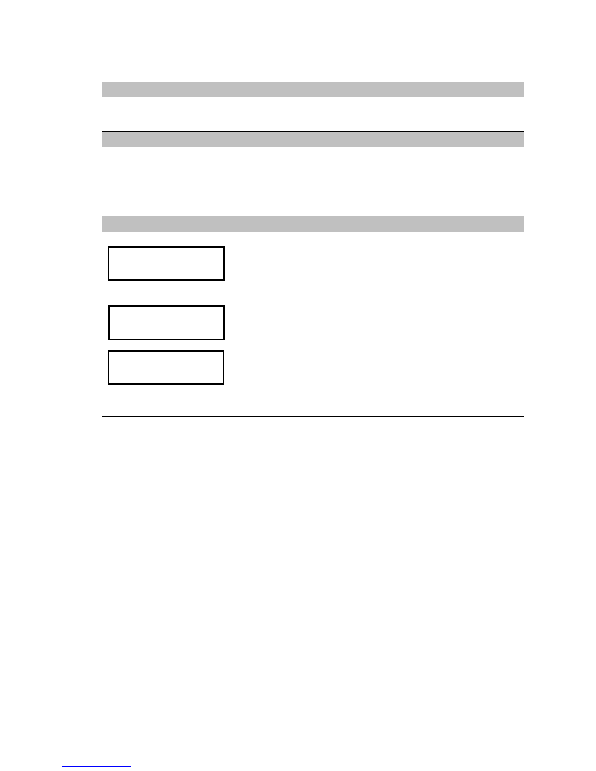
102
Reset Records
Clear the Total Coin PayIn and PayOut
Value Record
Default Definition
N/A Reset bookkeeping data.
LCM Descriptions
Press the Manual button.
Use A / C to scroll to EZ code 102.
Press F to enter.
Press F to confirm clearance of the memory.
LCM shows erased message when data has been erased successfully.
Manual to exit.
Reset Records
1
02
Reset Records
Are You Sure?
Data has been
erased
Page 19

19
Code LCM Display Function Description Accessibility
103
Accept/Reject Coin Switch
Set Accept or Reject to Coin
Denominations
Default Definition
All Accept Setup changer to accept or reject to each denomination.
LCM Descriptions
Press the Manual button.
Use A / C to scroll to EZ code 103.
Press F to enter.
Use B / E to switch coin values.
LCM shows current setting of the denomination.
Press F to change the setting. (Accept / Reject)
Press Manuel to save.
Manual to exit.
Code LCM Display Function Description Accessibility
104
Tube Open/Close Switch Set Open or Close to Coin Tubes
Default Definition
All ON On/off switch for Tube A, B, C, D, E, and F.
LCM Descriptions
Press the Manual button.
Use A / C to scroll to EZ code 104.
Press F to enter.
Use B / E to switch tubes.
Press F to change tube setting. (ON / OFF)
Press Manuel to save.
Manual to exit.
EUR$0.05:Accept
"F" to Change
Accept/Reject
Coin Switch 103
Tube Open/Close
Switch 104
TUBE A ON
"F" to Change
Page 20
20
Code LCM Display Function Description Accessibility
107
Configure Cash Float
Set Cash Float Configuration for Various
Coin Denominations
-Cash Float Mode only
Default Definition
Depends on region
Maximum level of each tube
Configure cash float level quantity of each coin value. Coin Changer can
save up to 3 types of cash float setting. A coin value’s maximum level
depends on the maximum level of tube multiple tube number.
Note! When coins reach defined cash float level amount, the overfloat
coins will enter changer’s cash box.
LCM Descriptions
Press the Manual button.
Use A / C to scroll to EZ code 107.
Press F to enter.
B / E to switch cash float type, A, B or C.
F to adjust selected cash float type.
LCM shows current setting.
B / E to switch coin values.
F to adjust quantity.
B / E to adjust level, +1 or -1.
A / C to adjust level, +10 or -10.
Press F to save.
Note! If LCM does not appear saved message, means the settings were
not saved, and please reconfirm and press the button F to save the
settings.
Press Manual to save the coin type configuration of all coin values. Changer
will inquire whether to apply the coin type configuration or not?
Press F to apply immediately, or D to save the type configuration only without
applying.
Manual to exit.
Configure
Cash Float 107
Float Type A
Save Changes?
D=NO, F=YES
EUR$ 0.05
Level TO CB 70
Q'TY?
70
Saved
Page 21

21
Code LCM Display Function Description Accessibility
108
Activate Cash Float
Set Cash Float Type for Various Coin
Denominations
-Cash Float Mode only
Default Definition
Configure Type of cash float for various coin denominations to be activated.
LCM Descriptions
Press the Manual button.
Use A / C to scroll to EZ code 108.
Press F to enter.
Use B / E button to scroll through types. (Type A, B or C)
Press F to save.
Manual to exit.
Code LCM Display Function Description Accessibility
109
Check Current Cash Float
Check current cash float setting of
various coin denominations.
-Cash Float Mode only
Default Definition
Check current cash float setting of various coin denominations.
LCM Descriptions
Press the Manual button.
Use A / C to scroll to EZ code 109.
Press F to enter.
Press F to enter cash float information acquiring mode.
Use B / E button to scroll through each coin value's cash float configuration.
When finished, press Manual button to exit.
Manual to exit.
Float Type A
Type A
Activated
Activate
Cash Float 108
$0.05 Cash Float
070
Check Current
Cash Float 109
Page 22
22
Code LCM Display Function Description Accessibility
110
Change Mgmt. Set the Change Return Mode
Default Definition
Highest Value
Setup change return by the original coin value or by the highest coin value.
Org. Coin Value: return by original inserted sequence.
Highest Value: return starting from highest coin value. When changer cannot
return by highest value, it returns by original coin value.
Note! This function only works with the JPSTD interface
LCM Descriptions
Press the Manual button.
Use A / C to scroll to EZ code 110.
Press F to enter.
Press F to change its current setting.
(Highest Value/Original Coin Value)
When finished, press Manual button to exit.
Manual to exit.
Code LCM Display Function Description Accessibility
111
Idle Display Set the Standby LCM Display Mode
Default Definition
Coin Q’TY
Change coin changer's LCM display in standby status.
Coin Q'TY: display coins in each tube.
Total Coin Value: display total amount of vending.
LCM Descriptions
Press the Manual button.
Use A / C to scroll to EZ code 111.
Press F to enter.
Press F again to change display method.
(Coin Q'TY/Total Coin Value)
When finished, press Manual button to exit.
Manual to exit.
Highest Value
"F" to Change
Change Mgmt.
110
Coin Q'TY
"F" to Chan
g
e
Idle Display
111
Page 23

23
Code LCM Display Function Description Accessibility
112
BA Type Setting Set the BA Interface
Default Definition
Select type of connected bill acceptor.
(Only work on ICT Bill Acceptor connect to Coin Changer)
Note! This is a special function. The Coin Changer must lap joint with
the ICT Bill Acceptor for this function to work.
LCM Descriptions
Press the Manual button.
Use A / C to scroll to EZ code 112.
Press F to enter.
Press F again to change BA type setting. (JPSTD/JPSTD with
escrow/MDB/MDB with escrow)
When finished, press Manual button to exit.
Manual to exit.
Code LCM Display Function Description Accessibility
113
Default Setting Restore to Default Factory Settings
Default Definition
N/A
Restore factory default setting. Example: cash float…etc.
Cash float setting will be reset to low level of each denomination.
LCM Descriptions
Press the Manual button.
Use A / C to scroll to EZ code 113.
Press F to enter.
Press F to restore factory setting mode.
Press F again to confirm of reset to factory default, changer restart
automatically. Otherwise, press Manual to cancel.
Manual to exit.
BA: JPSTD
"F" to Change
BA Type Setting
112
Are You Sure?
Default Setting
1
13
Page 24
24
Code LCM Display Function Description Accessibility
116
Cassette Type Coin Tube Configuration Mode -Special Function
Default Definition
Configure the tube coin assignment without change the firmware.
LCM Descriptions
Press the Manual button.
Use A / C to scroll to EZ code 116.
Press F to enter.
Use B / E button to scroll through different selections. (Please ask your dealer
or sales for the tube assignment availability.)
Press F to confirm tube coin assignment.
Changer inquires automatically whether to set tube inventory (cash float) to
maximum amount?
Press D to remain previous cash float setting.
Otherwise, press F to change cash float setting to maximum amount of the
selected tube configuration.
Manual to exit.
Tube Type 01
Configuration
Finished
Cassette Type
1
1
6
Coin Float->Max
D=NO , F=YES
Restore
Finished
Page 25
25
Code LCM Display Function Description Accessibility
117
Error Info Display Error Message Records
Default Definition
N/A
Display coin changer's last one error issue occurred during operation. Coin
Changer keeps last record of error message even after the error has been
solved.
LCM Descriptions
Press the Manual button.
Use A / C to scroll to EZ code 117.
Press F to enter.
Changer will display error message if there is any. Error message including
‘Sorting Error’, ‘TubeSensor Error’ or ‘Motor Error.’
When finished, press Manual button to exit.
Manual to exit.
Code LCM Display Function Description Accessibility
118
Bill(s) per Transaction
Set the Bill Acceptance Limitation for the
BA
-ICT BA Only
Default Definition
1
Configure limited number of bills accepted per transaction. (Only works on
ICT Bill Acceptor connect directly to the Coin Changer)
Configurable number of bill: 1 to 9
Note! This is a special function. The Coin Changer must be equipped
with the ICT Bill Acceptor for this function to work.
LCM Descriptions
Press the Manual button.
Use A / C to scroll to EZ code 118.
Press F to enter.
Use B / E button to change bill limitation number.
Note! The page below would appear after each save. If this page does
not appear, that means the settings were not saved, and please retry
setting.
When finished, press Manual button to exit.
Manual to exit.
No Error
Error Info
115
# of Bill
1 Bill(s)
Bill(s) per
Transaction 118
Configuration
Finished
Page 26
26
Code LCM Display Function Description Accessibility
119
CashFloat Mode Set Coin Tube Inventory Counting Mode
Default Definition
Cashfloat Mode
Default amount is the maximum
level of each tube.
Select counting method of coin tube inventory.
Cashfloat Mode: Changer system keeps counting coin number among
tubes. Even after reboot or power reset, coin inventory data remains in
memory.
Sensor Mode: After reboot or power reset, coin changer detects coin
inventory in tubes through low level sensor and high level sensor. Changer
displays N, L or H according to coin amount:
N – Tube empty
L – Coins reach low level amount
H – Coins reach high level amount
Some operational functions are unavailable under sensor mode, including
100, 107, 108, 109 and 111.
LCM Descriptions
Press the Manual button.
Use A / C to scroll to EZ code 119.
Press F to enter.
Changer displays current inventory counting mode.
Press F to change inventory counting method.
Note! When counting method is changed to Cashfloat mode, the
cashfloat setting is changed to maximum amount automatically.
When finished, press Manual button to exit.
Manual to exit.
Cash Float
"F" to Change
CashFloat Mode
119
A=N , B=N , C=N
D
=L , E=H , F=H
Page 27
27
Code LCM Display Function Description Accessibility
120
Set ID Set Customer & Machine Number
Default Definition
N/A
Configure Customer & Machine Number of Coin Changer
Configurable Range:
Customer Number contains 16 digits and each digit applies to 0 - 9.
Machine Number contains 12 digits and each digit applies to 0 - 9 or A – Z.
LCM Descriptions
Press the Manual button.
Use A / C to scroll to EZ code 120.
Press F to enter.
Use B / E button to select Customer Number or Machine Number to setup.
Press F to set the ID.
Press B / E to plus/minus number.
Press A / C to shift configured digit.
When finished, press F to save the ID.
Manual to exit.
Set ID
Machine Number
Set ID
120
Set ID
Customer Number
Machine Number
123456789012
Customer Number
1234567890123456
Page 28
28
Code LCM Display Function Description Accessibility
121
Coin->CashBox Setting
Set Coin Acceptance to Cash Box
Condition
Default Definition
Same Coin Value
Setup conditions of coin acceptance to cash box.
Same Coin Value: After a coin accepted, check the accepted denomination
total in changer. When changer can return the same denomination coins in
the changer, the coin falls into cash box, otherwise it is rejected.
Total Coin Value: After a coin accepted, check total accepted value. When
changer can return the value, the accepted coin falls into cash box, otherwise
it is rejected.
Force Reveivin
g
:
Coin falls into cash box.
LCM Descriptions
Press the Manual button.
Use A / C to scroll to EZ code 121.
Press F to enter.
Changer displays current setting.
Press F to change setting. (Same Coin Value / Total Coin Value)
When finished, press Manual button to exit.
Manual to exit.
Code LCM Display Function Description Accessibility
122
Expansion Escrow Setting Set Escrow for NTD 50
This function only apply to NTD
Type Changer.
Default Definition
OFF
Setup condition of 50NTD into escrow or cash box.
Escrow ON: 50NTD coin goes into cash box when changer can return from
cassette; otherwise 50NTD coin is returned.
Escrow OFF: 1
st
and 2nd 50NTD coins go into escrow, 3rd one is returned.
LCM Descriptions
Press the Manual button.
Use A / C to scroll to EZ code 122.
Press F to enter.
Changer displays current escrow setting.
Press F to change escrow setting to ON or OFF.
When finished, press Manual button to exit.
Manual to exit.
Same Coin Value
"F" to Change
Coin->CashBox
Setting 121
Escrow ON
"F" to Change
Expansion Escrow
Setting 122
Page 29
29
Code LCM Display Function Description Accessibility
123
Sensor Inventory
Adjustment
Detect Tube Inventory
-Only MDB for TWD
、
SGD
、
MYR、THB、CNY
Default Definition
N/A
Detect tube inventory and overwrite tube count data.
LCM Descriptions
Press the Manual button.
Use A / C to scroll to EZ code 123.
Press F to enter.
Press D to cancel.
Press F to read the coin inventory and save the inventory amount.
The changer displays message as left when tube count has been overwritten
successfully, then back to main configuration screen automatically.
Manual to exit.
Code LCM Display Function Description Accessibility
124
Reserved Coin Set Reserved Coin Function
Default Definition
ON
Setup reserved coin function to ON or OFF.
Reserved Coin ON: Changer will not pay out to last coin among operation,
specific number of coins will reserve inside tubes, around 4 coins. The
reserved coin number depends on different region.
Reserved Coin OFF: Changer pays out to last coin in tubes.
LCM Descriptions
Press the Manual button.
Use A / C to scroll to EZ code 124.
Press F to enter.
Changer displays current setting.
Press F to change reserved coin setting to ON or OFF.
When finished, press Manual button to exit.
Manual to exit.
Scan Inventory?
D=NO, F=YES
Sensor Inventory
Adjustment 123
Finished
ON
"F" to Change
Reserved Coin
124
Page 30
30
Code LCM Display Function Description Accessibility
125
Accessibility options
Set LCM accessibility under door-switch
status and password security
Default Definition
Door-ON
PW-ON
Setup LCM accessibility under door-switch status and setup password
security.
Door-ON: LCM inaccessible under door closing
Door-OFF: LCM accessible under door closing
PW-ON: Require password to access all LCM function
PW-OFF: Require no password to access all LCM function
LCM Descriptions
Press the Manual button.
Use A / C to scroll to EZ code 125.
Press F to enter.
Press B / E button to select setting.
Press F to save the setting.
The changer display saved message when setting has been overwritten
successfully..
Manual to exit.
Door: ON
Password: OFF
Accessibility
options 125
Saved
Page 31

31
Code LCM Display Function Description Accessibility
126
Manual Inventory
Adjustment
Refill Coin Inventory by inserting coins
into tube cassette directly
-Only MDB for TWD
、
SGD
、
MYR、THB、CNY
Default Definition
N/A
Allow user to refill coins by inserting coins into tube cassette directly. The
tube refill procedure is select code 126, check refill amount on display, take
out cassette, refill coins into cassette, put cassette back then push Enter to
finish refill procedure. Please notice that changer do not count refilled coin
amount, user need to put exact coin amount as requirement. The required
coin amount may vary according to code 108 setting.
LCM Descriptions
Press the Manual button.
Use A / C to scroll to EZ code 126.
Press F to enter.
LCM displays required refill amount of each tube.
Make sure cassette has enough coins as required.
Press F to save.
The changer display finished message when setting has been overwritten
successfully.
Manual to exit.
A=-- B=-- C=-D=-- E=-- F=--
Manual Inventory
Ad
j
ustment 126
Saved?
D=NO , F=YES
Overwrite
Finished
Page 32

32
Code LCM Display Function Description Accessibility
127
Residual Credit Setup residual credit
Default Definition
Delete
When the Coin Changer cannot return the coins completely, leave the surplus
credit in VMC or delete it. User allow to setup residual credit, vending sales
adjusted by Changer. Please notice that the function requires VMC support,
allow the residual credit to stay and further vend can be made.
LCM Descriptions
Press the Manual button.
Use A / C to scroll to EZ code 127.
Press F to enter.
Changer displays current setting.
Press F to change reserved coin setting to Delete or Not Delete.
When finished, press Manual button to exit.
Manual to exit.
Delete
"F" to Change
Residual Credit
127
Page 33

33
Code LCM Display Function Description Accessibility
128
Token Learning Mode Token learning mode
-CC6100M
、
CC6100E
Default Definition
User can teach Changer 2 kinds of token through LCM. (Token A or B)
Each token requires at least 3 for learning.
LCM Descriptions
Press the Manual button.
Use A / C to scroll to EZ code 128.
Press F to enter.
Use B / E button to select token A or B.
Press F to configure token, to learn or to delete.
To learn token, use B / E button to select token learn function.
Press F to learn.
Follow display instruction to insert token. 3 to 10 tokens are required
for learning.
When finished, press Manual button to exit.
LCM shows success message when token learning is successful.
Otherwise, LCM shows failure when token learning is fail.
To delete token, use B / E button to select token delete function.
Press F to delete.
LCM display erased message when setting has been erased successfully.
Manual to exit.
Token Type A
Token Learning
Mode 128
Token A
Learn
Learn Mode:
Insert Token
Success
Token A
Delete
Token Erased
Page 34

34
Code LCM Display Function Description Accessibility
130
Reject Lever Setting Set no refund after inserting payment
-CC6100M
、
CC6100E
Default Definition
ON
OFF
(
INR only)
User can set vending machine to no refund after inserting payment.
ON: set vending machine to refund by pressing reject button
OFF: set vending machine to no refund.
LCM Descriptions
Press the Manual button.
Use A / C to scroll to EZ code 130.
Press F to enter.
Changer displays current setting.
Press F to change setting. (ON or OFF)
When finished, press Manual button to exit.
Manual to exit.
Code LCM Display Function Description Accessibility
131
Acceptance limit For
Changer
Set Credit Acceptance Limit
-6100M KRW only
Default Definition
0
When the total credit of coins and bills exceeds the acceptance limit (over the
limitation amount), the Coin Changer & Bill Accepter will be disabled. And the
LCM of Coin Changer will show “ Acceptance Limit Reached!”
(When this option setting is “0”, there is no limit.)
LCM Descriptions
Press the Manual button.
Use A / C to scroll to EZ code 208.
Press F to enter.
LCM displays current setting.
Press B / E to plus/minus number.
Press A / C to shift configured digit.
When finished, press F to save.
Manual to exit.
Acceptance Limit
For Chan
g
er 208
Acceptance Limit
$00.0
Acceptance Limit
Saved
Reject Lever
Setting 130
ON
"F" to Change
Page 35

35
Code LCM Display Function Description Accessibility
132
Maximum for Insert Q'TY
Set limitation of inserted coins in single
transaction
-CC6100M KRW only
Default Definition
30
Use can define a limitation number of coins during a single vend.
When inserted coins exceed the number of limitation, the exceeded coins will
be returned.
LCM Descriptions
Press the Manual button.
Use A / C to scroll to EZ code 132.
Press F to enter.
LCM displays current setting.
Press B / E to plus/minus number.
Press A / C to shift configured digit.
When finished, press Manual button to save and exit.
Manual to exit.
Maximum for
Insert Q'TY 132
Acceptance Limit
00 PCS
Acceptance Limit
Saved
Page 36

36
Code LCM Display Function Description Accessibility
133
Decimal and Scaling Set Decimal point and Scaling Factor
-CC6100M
、
CC6100E
Default Definition
Decimal 0
Scaling 1
Different country product have
different setting
Setup the decimal point and scaling factor of vending values to VMC.
To prevent the counting value error, please make sure the value can be
divided to integer under the decimal and scaling setting.
Decimal Point: 0 – 2
Scaling Factor: 1 – 255
LCM Descriptions
Press the Manual button.
Use A / C to scroll to EZ code 133.
Press F to enter.
To setup Decimal, use B / E button to select Decimal.
Press F to set.
LCM displays current setting.
Press B / E to plus/minus number.
When finished, press F to save.
To setup Decimal, use B / E button to select Decimal.
Press F to set.
LCM displays current setting.
Press B / E to plus/minus number.
When finished, press F to save.
Manual to exit.
Decimal and
Scaling 133
Decimal
Decimal Place: 0
Scaling
Scaling
Factor : 001
Saved
Saved
Page 37

37
Code LCM Display Function Description Accessibility
134
Currency Code Setting Currency Code
Default Definition
Base on MDB protocol
Currency code Base on MDB protocol
LCM Descriptions
Press the Manual button.
Use A / C to scroll to EZ code 134.
Press F to enter.
Press A / C to shift configured digit.
Press B / E to plus/minus number.
Press F to save.
Manual to exit.
Code LCM Display Function Description Accessibility
135
Error Report Setting Error Report Function
Default Definition
OFF
ON: Report error message to VMC
OFF: Not report error message to VMC
LCM Descriptions
Press the Manual button.
Use A / C to scroll to EZ code 135.
Press F to enter.
Press F to Change Error report function.
When finished, press Manual button to save and exit.
Manual to exit.
Currency Code
134
Currency Code
1810
Saved
Error Report
To VMC 135
Error Report:OFF
“F” to Change
Error Report:ON
“F” to Change
Page 38

38
Code LCM Display Function Description Accessibility
136
Payout Method
Setting Payout Method
(
Level 2)
Default Definition
Combination
Set CC6100 payout method when it receives a level 2 DISPENSE command.
Combination
:
When the coin value which VMC assign to payout is empty,
CC6100 will payout other value to complete payout command.
Regular
:
When the coin value which VMC assign to payout is empty,
CC6100 will do nothing.
LCM Descriptions
Press the Manual button.
Use A / C to scroll to EZ code 136.
Press F to enter.
Press F to Change Payout Method.
When finished, press Manual button to save and exit.
Manual to exit.
Payout Method
136
Combination
“F” to Change
Regular
“F” to Change
Page 39

39
3.5. Executive Setting Function Descriptions
Code LCM Display Function Description Accessibility
200
Sell Mode Set Single Vend or Multi Vend
Executive only
LCM Descriptions
Single Vend
Setup condition of vending criteria to single vending mode or multi vending
mode.
Single Vend: After a transaction is made, vending machine returns changes
and closes the transaction.
Multi Vend: After a transaction is made, vending machine does not return
change and the transaction stays open unless return lever is triggered.
LCM Descriptions
Press the Manual button.
Use A / C to scroll to EZ code 200.
Press F to enter.
Changer displays current setting.
Press F to change setting. (Single or Multi)
When finished, press Manual button to exit.
Manual to exit.
Code LCM Display Function Description Accessibility
201
Price Display
Executive only
Default Definition
Disable
Setup whether to display product price on VMC monitor or not.
Disable: not to display product price
Enable: display product price
LCM Descriptions
Press the Manual button.
Use A / C to scroll to EZ code 201.
Press F to enter.
LCM displays current setting.
Press F to change setting. (Disable or Enable)
When finished, press Manual button to exit.
Manual to exit.
Sell Mode
200
MODE: Single
"F" to Change
Price Display
201
MODE: Disable
"F" to Change
Page 40

40
Code LCM Display Function Description Accessibility
202
Product Price Set Product Price Holding by Changer
Executive only
Default Definition
N/A
Setup product price. The price is applied only when it is hold by changer. To
set price holding mode, please refer to code 203.
LCM Descriptions
Press the Manual button.
Use A / C to scroll to EZ code 202.
Press F to enter.
Use B / E button to select channel.
Press F to configure channel.
LCM shows current price.
Press B / E to plus/minus number.
Press A / C to shift configured digit.
When finished, press F to save.
When code 204 is set to Enable, the 2nd bonus price in the right side can be
set.
LCM shows current price.
Press B / E to plus/minus number.
Press A / C to shift configured digit.
When finished, press F to save.
Manual to exit.
Channel: NO.01
"F" to Chan
g
e
Product Price
202
Set Price
$01.00
Set Price
Finished
Cash cashless
$02.00 $01
.
0
0
Set Price
Finished
Page 41

41
Code LCM Display Function Description Accessibility
203
Price Holding Set Price Holding by Changer or VMC
Executive only
Default Definition
VMC Setup whether the product price is hold by Changer or VMC.
LCM Descriptions
Press the Manual button.
Use A / C to scroll to EZ code 203.
Press F to enter.
LCM displays current setting.
Press F to change setting. (VMC or Changer)
When finished, press Manual button to exit.
Manual to exit.
Code LCM Display Function Description Accessibility
204
2nd Price For Cashless
Set 2nd price for cashless function on or
off
Executive only
Default Definition
Disable Setup whether the 2nd price for cashless function to on or off.
LCM Descriptions
Press the Manual button.
Use A / C to scroll to EZ code 204.
Press F to enter.
LCM displays current setting.
Press F to change setting. (Enable or Disable)
When finished, press Manual button to exit.
Manual to exit.
Price Holding
203
MODE: VMC
"F" to Change
2nd Price For
Cashless
2
04
Enable
"F" to Change
Page 42

42
Code LCM Display Function Description Accessibility
205
Enable Bill Acceptor Set BA enable with or without e-key
Executive only
Default Definition
Always
Setup Bill Acceptor enable with or without e-key connection.
Always: BA always enable, requires no e-key connection.
If card present: BA only enable under e-key connection.
LCM Descriptions
Press the Manual button.
Use A / C to scroll to EZ code 205.
Press F to enter.
LCM displays current setting.
Press F to change setting. (Always or If card present)
When finished, press Manual button to exit.
Manual to exit.
Code LCM Display Function Description Accessibility
206
Decimal Adjustment Decimal Setting
Executive only
Default Definition
Depends on region
Change the decimal point setting to display on VMC under executive
interface.
Decimal digit from 0 to 2 can be set.
Note! Some region may have limitation on decimal digit setting.
Note! After 206 setting changed, other functions including 202, 208 and
209 would restore to default. Please be sure to set function 206 in the
beginning.
LCM Descriptions
Press the Manual button.
Use A / C to scroll to EZ code 206.
Press F to enter.
LCM displays current setting.
Use B / E button to add or minus the digit of decimal point from 0 to 2..
When finished, press F to save the decimal point position.
Manual to exit.
Enable Bill
Acceptor 205
Always
"F" to Change
Decimal
Adjustment 206
Decimal: 0
Saved
Page 43

43
Code LCM Display Function Description Accessibility
207
Residual Credit Setup residual credit
Executive only
Default Definition
Not Delete
When the Coin Changer cannot return the coins completely, leave the surplus
credit in VMC or delete it.
LCM Descriptions
Press the Manual button.
Use A / C to scroll to EZ code 207.
Press F to enter.
LCM displays current setting.
Press F to change setting. (Delete or Not Delete)
When finished, press Manual button to exit.
Manual to exit.
Code LCM Display Function Description Accessibility
208
Acceptance Limit For
Changer
Set Credit Acceptance Limit
Executive only
Default Definition
30
When the total credit of coins and bills exceeds the acceptance limit (over the
limitation amount), the Coin Changer & Bill Accepter will be disabled. And the
LCM of Coin Changer will show “ Acceptance Limit Reached!”
(When this option setting is “0”, there is no limit.)
LCM Descriptions
Press the Manual button.
Use A / C to scroll to EZ code 208.
Press F to enter.
LCM displays current setting.
Press B / E to plus/minus number.
Press A / C to shift configured digit.
When finished, press F to save.
Manual to exit.
Residual Credit
207
Delete
"F" to Change
Acceptance Limit
For Changer 208
Acceptance Limit
$00.0
Acceptance Limit
Saved
Page 44

44
Code LCM Display Function Description Accessibility
209
Credit Limit For Cashless Set Credit limit for cashless
Executive only
Default Definition
30
When the top-up credit of cashless device (E-key) exceeds the credit limit,
the Coin Changer & Bill Accepter will be disabled. And the LCM of Coin
Changer will show “Cashless Limit Reached!”.
(When this option setting is “0”, there is no limit.)
LCM Descriptions
Press the Manual button.
Use A / C to scroll to EZ code 209.
Press F to enter.
LCM displays current setting.
Press B / E to plus/minus number.
Press A / C to shift configured digit.
When finished, press F to save.
Manual to exit.
Credit Limit For
Cashless 209
Cashless Limit
$00.00
Cashless Limit
Saved
Page 45

45
Code LCM Display Function Description Accessibility
210
Bill(s) per Transaction Set BA limitation per transaction
Executive only
Default Definition
1
The maximum Qty of bills for Bill Accepter per transaction:
When 1) Coin Changer is able to return the bill value and 2) the bill Qty is less
than the maximum Qty of bills for Bill Accepter, the Bill Accepter will stack the
bill into the cash box while the bill has been inserted, otherwise the bill will
hold in escrow.
Number 1 to 9 can be set.
Note! 210 function only available when BA set Changer as host.
LCM Descriptions
Press the Manual button.
Use A / C to scroll to EZ code 210.
Press F to enter.
Use B / E button to change bill limitation number.
Note! The page below would appear after each save. If this page does
not appear, that means the settings were not saved, and please retry
setting.
When finished, press F to save.
Manual to exit.
Bill(s) per
Transaction 210
# of Bill
1 Bill(s)
Configuration
Finished
Page 46

46
Code LCM Display Function Description Accessibility
211
Exact Change Notice Set exact change notice on display
Executive only
Default Definition
Not Active
When the Coin Changer may not return the coins completely, choose to
display exact change notice on VMC or not.
Active: Display depends on reserve coin setting (124). When reserve coin
sets to ON, the smallest three denominations amounts under 10 coins,
display shows “No Change.” When reserve coin sets to OFF, the smallest
three denominations amounts under 6 coins, display shows “No Change.”
Not Active: hide “No Change” message
LCM Descriptions
Press the Manual button.
Use A / C to scroll to EZ code 211.
Press F to enter.
LCM displays current setting.
Press F to change setting. (Active or Not Active)
When finished, press Manual button to exit.
Manual to exit.
Code LCM Display Function Description Accessibility
212
Exchange Rate Setting Exchange Rate
Executive only
Default Definition
Can be set through the LCM to the second country of the second country
currency, according to the user needs second country currency can be
converted into the main country currency to the amount of VMC
LCM Descriptions
Press the Manual button.
Use A / C to scroll to EZ code 212.
Press F to enter.
Press the Enter Button to the menu screen, Use A / C Button to select the
currency to be modified.
Press the F key to enter the currency value to set the conversion rate, press
the B / E key to set the amount
Pressing the Manual key after setting is complete and you can jump back to
the C step and press the manual key again. CC6100 will reboot to initialize
the set exchange rate.
When finished, press Manualbutton to exit.
Manual to exit.
Exact Change
Notice 211
Not Active
"F" to Change
Exchange Rate
212
EUR €10.05
=001 CZK
Page 47

47
3.6. DIP Switch Setting
FUNCTION
SW1 SW2 SW3 SW4 SW5 SW6 SW7 SW8
High anti-counterfeiting (1st coin value)
ON
High acceptance (1st coin value)
OFF
High anti-counterfeiting (2nd coin value)
ON
High acceptance (2nd coin value)
OFF
High anti-counterfeiting (3rd coin value)
ON
High acceptance (3rd coin value)
OFF
High anti-counterfeiting (4th coin value)
ON
High acceptance (4th coin value)
OFF
Reserved (MDB)
ON
Reserved (Executive)
OFF
Reserved
ON
Reserved
OFF
Calibration Mode
ON
Preset to OFF
OFF
Reserved (Turn off the sleep mode)
ON
Reserved (Turn on the sleep mode)
OFF
Note:
• SW3-ON,High anti-counterfeiting:CNY $1、RUB $5、TWD$50
• SW4-ON,High anti-counterfeiting:RUB$10
• Acceptance rate setting, SW1 to SW4, is limited to some regions or denominations.
Please contact your local dealer for further information.
• For SW7 calibration mode instruction, please insert coin denominations in sequence
displayed on LCM, or refer to installation guide for detailed information.
• Only some previous CC6100E model can apply to DIP SW5 function.
• Only some previous CC6100S model can apply to DIP SW8 function.
Page 48

48
4.
Harness Application
4.1. List of Main Wire Harness:
Interface
Used Voltage
Description
Harness
JPSTD
24V DC Power & *Data Comm. 55cm
WEL-RCC24
JPSTD
24V DC
Power & *Data Comm. 75cm
WEL-RCC50
JPSTD
24V DC
Power & *Data Comm. 95cm
WEL-RCC49
MDB
20 - 45V DC
Power & *Data Comm. 57cm
WEL-RCC23
MDB
20 - 45V DC
Power & *Data Comm. 77cm
WEL-RCC51
MDB 20 - 45V DC
Power & *Data Comm. 97cm
WEL-RCC47
Power Saving 10 - 45V DC Power & *Data Comm. 97cm
3-CA-RCC71-01
MDB &
MDB Peri
p
heral
24V AC Power & *Data Comm. 97cm WEL-RCC72
Executive 24V AC Power & *Data Comm. 97cm
WEL-RCC54
-
- Download Box Cable (Optional) WEL-RCC42
Warning!! Do not plug both MDB and Executive connecter to VMC board
simultaneously!! It may cause damage of VMC board.
4.2. List of Wire Harness for ICT Bill Acceptor:
Interface
ICT Bill Acceptor Harness
JPSTD
NV Series
WEL-RCC31 +WEL-RCC32
WEL-RCC48
MDB Bill Acceptor WEL-RCC48 +WEL-RCC46
MDB
NV Series
WEL-RCC67 +WEL-RCC68
MDB Bill Acceptor
WEL-RCC48 +WEL-RCC46
WEL-RCC67
Executive
MDB Bill Acceptor
WEL-RCC72
Please refer to Chapter 3-2 < Set the BA Interface > for setting instruction
Page 49

49
4.3. Wire Harness Pin Assignment for JPSTD interface
«
Main wire harness
»
Page 50

50
Page 51

51
«
JPSTD wire harness for ICT Bill Acceptor
»
Page 52

52
Page 53

53
4.4. Wire Harness Pin Assignment for MDB interface
«
Main wire harness
»
Page 54

54
Page 55

55
«
MDB wire harness for ICT Bill Acceptor
»
Page 56

56
Page 57

57
4.5. Wire Harness Pin Assignment for Executive & MDB Interface
Interface Used Voltage Harness
Executive 24V AC WEL-RCC54
Interface Peripheral Harness
Executive MDB Peripheral WEL-RCC72 (MDB Peripheral)
WEL-RCC54
Page 58

58
Interface Used Voltage Harness
MDB 10 – 45V DC WEL-RCC72 (MDB)
Interface Peripheral Harness
MDB MDB Peripheral WEL-RCC72 (MDB Peripheral)
Warning!! Do not plug both MDB and Executive connector to VMC board
simultaneously!! It may cause damage of VMC board.
Page 59

59
4.6. Wire Harness Pin Assignment for Download Box
Page 60

60
5.
I/O Circuit
«
JPSTD Interface
»
Page 61

61
«
MDB Interface
»
Page 62

62
«Executive
Interface
»
Page 63

63
6.
Maintenance
To ensure the coin changer operate correctly, following maintenance steps are required.
ICT suggests cleaning every six month; however, under heavy usage conditions or
locations the maintenance may need to be more frequent.
Warning: Before removing the coin changer, please make sure to turn the
power off!
Clean the dust-proof sheet
Page 64

64
Page 65

65
7.
Troubleshooting
7.1. Error Code Messages
Code Cause LED
E10 LCM Panel Open 5 red + 2 red
E11 Checksum Error Red Light
E12 Signal from the coin base was not received when the power was turned on. Red Light
E13
Two seconds after activation, the SYSTEM did not wait for the READY signal
from the DEVICE and jumped to the exception.
1 red
Two seconds after a transaction, the SYSTEM did not wait for the READY
signal triggered by the DEVICE.
E14 Coil 1 is damaged. 3 red + 1 red
E15 Coil 2 is damaged. 3 red + 2 red
E16 Coil 3 is damaged. 3 red + 3 red
E17 Low level LED is damaged. 3 red + 5 red
E18 Coin separator sensor problem. 3 red + 4 red
E19 The deck is open for over 30 seconds. 5 red + 1 red
E20 Both the first and second group motors cannot be positioned. 7 red
E21
The first motor group cannot be positioned. The first motor group might be
damaged, coin or foreign objects might have caused the motor to stuck, coins
are stuck in the coin tube, or the semicircle disk has derailed.
None
E22
The second motor group cannot be positioned. The second motor group might
be damaged, coin or foreign objects might have caused the motor to stuck,
coins are stuck in the coin tube, or the semicircle disk has derailed.
None
E23 Broke away or incorrectly positioned coin tubes. 5 red
E24
Coins got stuck at the coin separation area or the coin tube opening twice in a
row, causing the HI Level Sensor to fail to detect the coin twice in a row.
6 red + 4 red
E25 A Tube Low Level = empty, HI Level = full at setup. None
E26 B Tube Low Level = empty, HI Level = full at setup. None
E27 C Tube Low Level = empty, HI Level = full at setup.
None
E28 D Tube Low Level = empty, HI Level = full at setup.
None
E29 E Tube Low Level = empty, HI Level = full at setup.
None
E30 F Tube Low Level = empty, HI Level = full at setup.
None
E31 Barcode Reader Error
None
E32 The three sets of LEDs used to distinguish Coin size have been damaged.
None
E33 Recosnition Ver Error
None
None The „Inhibit“ signal transmitted by the interface. 2 red
Page 66

66
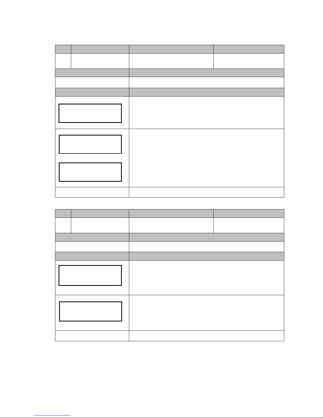
7.2. Error Handling
«
LCM Panel Open
»
Code: E10
LED Light Display: 5 red+ 2 red
LCM Display: As shown in figure
Cause: LCM Panel Open
Corrective Measure: Close the
LCM panel and verify that the
latch is in place. If the problem
cannot be solved, notify ICT
personnel for support.
«
Checksum Error
»
Code: E11
LED Light Display: Red light
LCM Display: As shown in figure below
Cause: Check Sum Error.
Corrective Measure: Notify the ICT personnel for support.
Sorting Module
Door Open E10
Check Sum Error
E11
Page 67

67
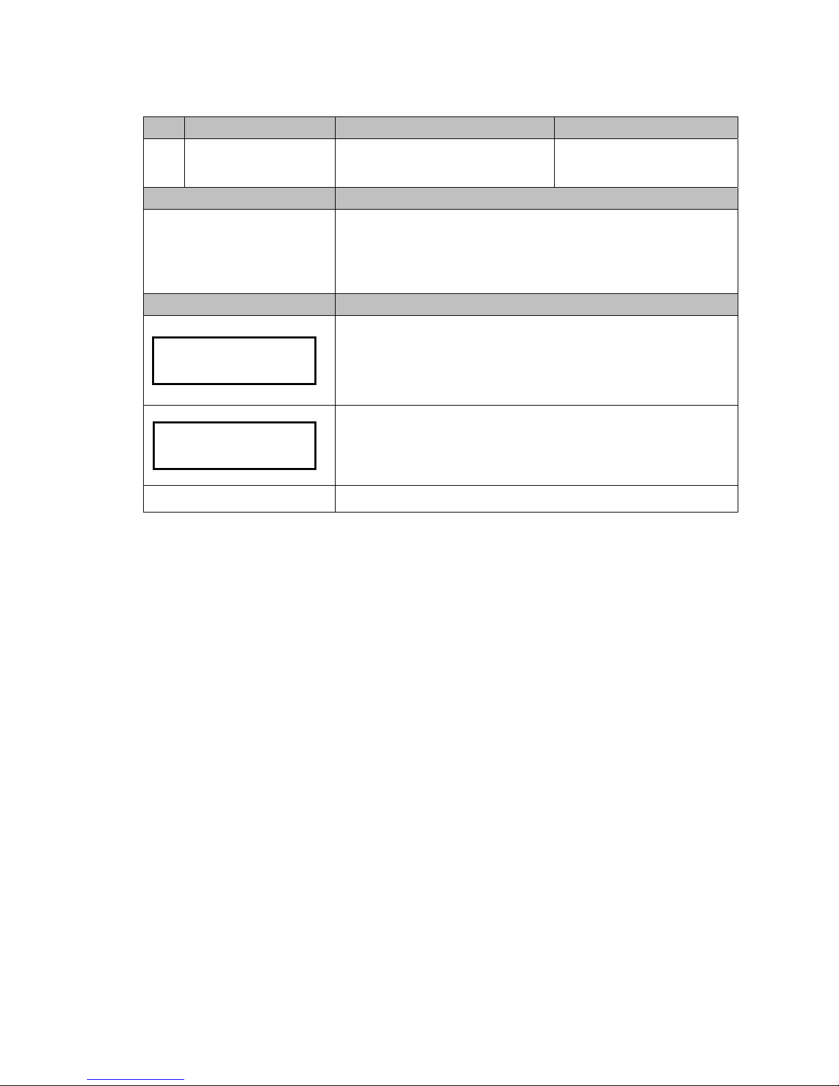
«
Payout Mode Error
»
Code: E12
LED Light Indicator: Red light
LCM Display: As shown in figure below
Cause: Signal from payout module was not
received when power was turned on.
Corrective Method: Ensure that the signal wire
is connected to the payout module.
«
Communication Error
»
Code: E13
LED Light Display: 1 red
LCM Display: As shown in figure
Cause:
1. Two seconds after activation, the SYSTEM did not wait for the READY signal from
the DEVICE and jumped to the exception mode.
2. Two seconds after a transaction, the SYSTEM did not wait for the READY signal
triggered by the DEVICE.
Corrective Measure:
1. Ensure that the machine interface and the VMC
interface are consistent.
2. Ensure that the interface transmission wire is
properly connected.
Payout Module Error
E12
No Communication
with VMC E13
Page 68

68
«
#1 Coil Error
»
Code: E14
LED Light Display: 3 red+ 1 red
LCM Display: As shown in figure below
Cause: Coil 1 is damaged.
Corrective Measure: Notify the ICT personnel
«
#2 Coil Error
»
Code: E15
LED Light Display: 3 red + 2 red
LCM Display: As shown in figure below
Cause: Coil 2 is damaged.
Corrective Measure: Notify the ICT personnel
«
#3 Coil ERR
»
Code: E16
LED Light Display: 3 red +3 red
LCM Display: As shown in figure below
Cause: Coil 3 is damaged.
Corrective Measure: Notify the ICT personnel
«
Low Level LED Error
»
Code: E17
LED Light Display: 3 red+ 5 red
LCM Display: As shown in figure below
Cause: Low level LED is damaged. Otherwise, optical lens may be covered by dirt or
dust.
Corrective Measure: When error is detected, changer retries once a minute for 10 times. It
will stop if the problem is not resolved after 10 times retry. Clean
the optical lens with soft fabric. If the problem cannot be solved,
notify ICT personnel for support.
Coil Error #1
E14
Coil Error #2
E15
Coil Error #3
E16
Tube Detection
Sensor Error E17
Page 69

69
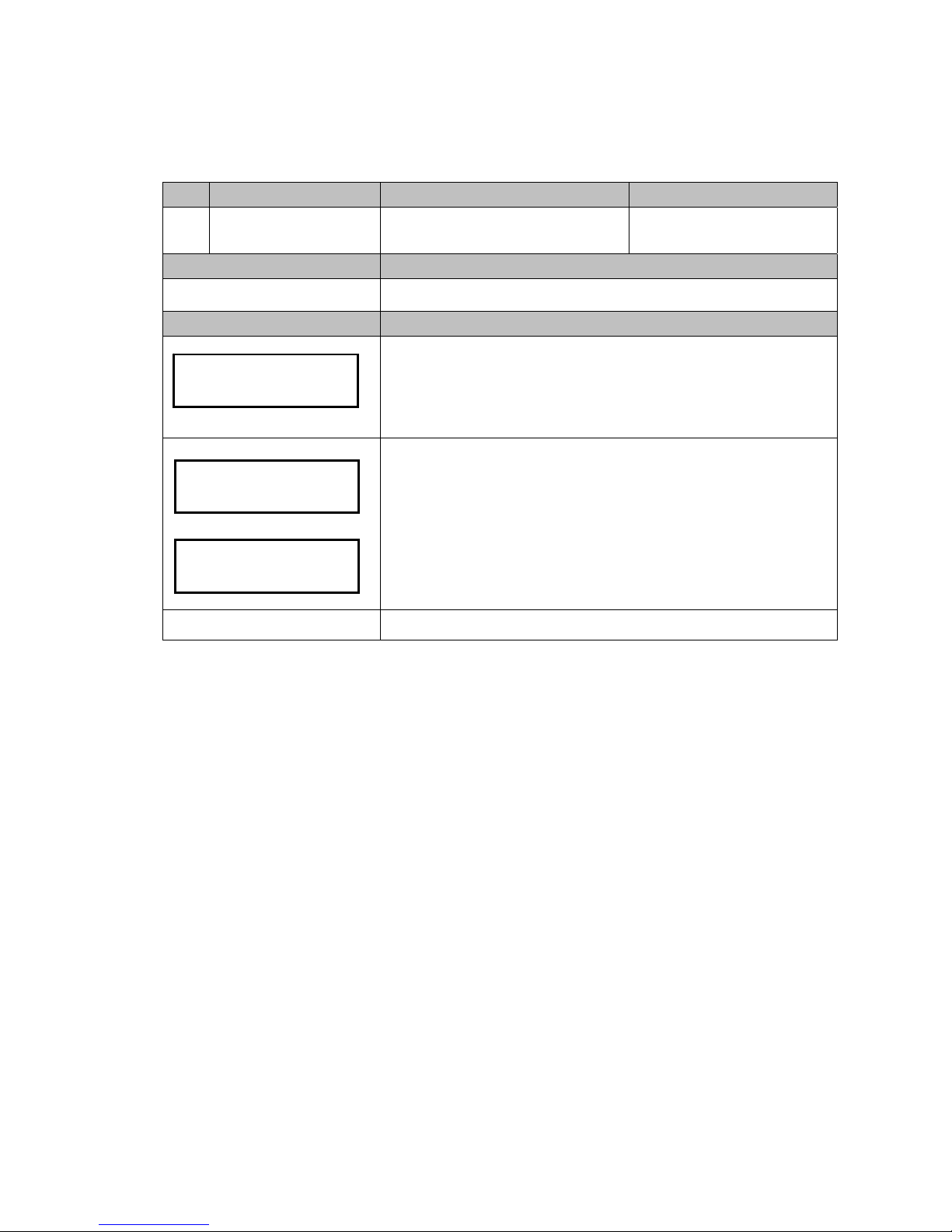
«
Sort Sensor Error
»
Code: E18
LED Light Display: 3 red + 4 red
LCM Display: As shown in figure below
Cause: Coin separator sensor problem.
Corrective Measure:
1. Make sure that the reflective prism is not dirty or blocked by foreign objects. If
it is, remove the foreign object and clean the reflective prism.
2. Changer retries once a minute for 10 times when error is detected. It will stop if
the problem is not resolved after 10 times retry.
Sorting Module
Sensor Error E18
Page 70

70
«
Deck Open Problem
»
Code: E19
LED Light Display: 5 red +1 red
LCM Display: As shown in figure below
Cause:
1. The deck is open for over 30 seconds.
2. The reject bar has problem.
Corrective Measure:
1. Close the deck and reactive the power.
2. Retry once a minute for 10 times, if the problem is not
resolved then remove the LCM panel to leave this
exception and notify ICT personnel for support.
«
Motor Error:A&B
»
Code: E20
LED Light Display: 7 red
LCM Display: As shown in figure below
Cause: Both the first and second group motors cannot be positioned.
Corrective Measure: Please see reference instructions for “E21” and “E22” below.
Flight Deck
Error E19
Coin Jam
E20
Page 71

71
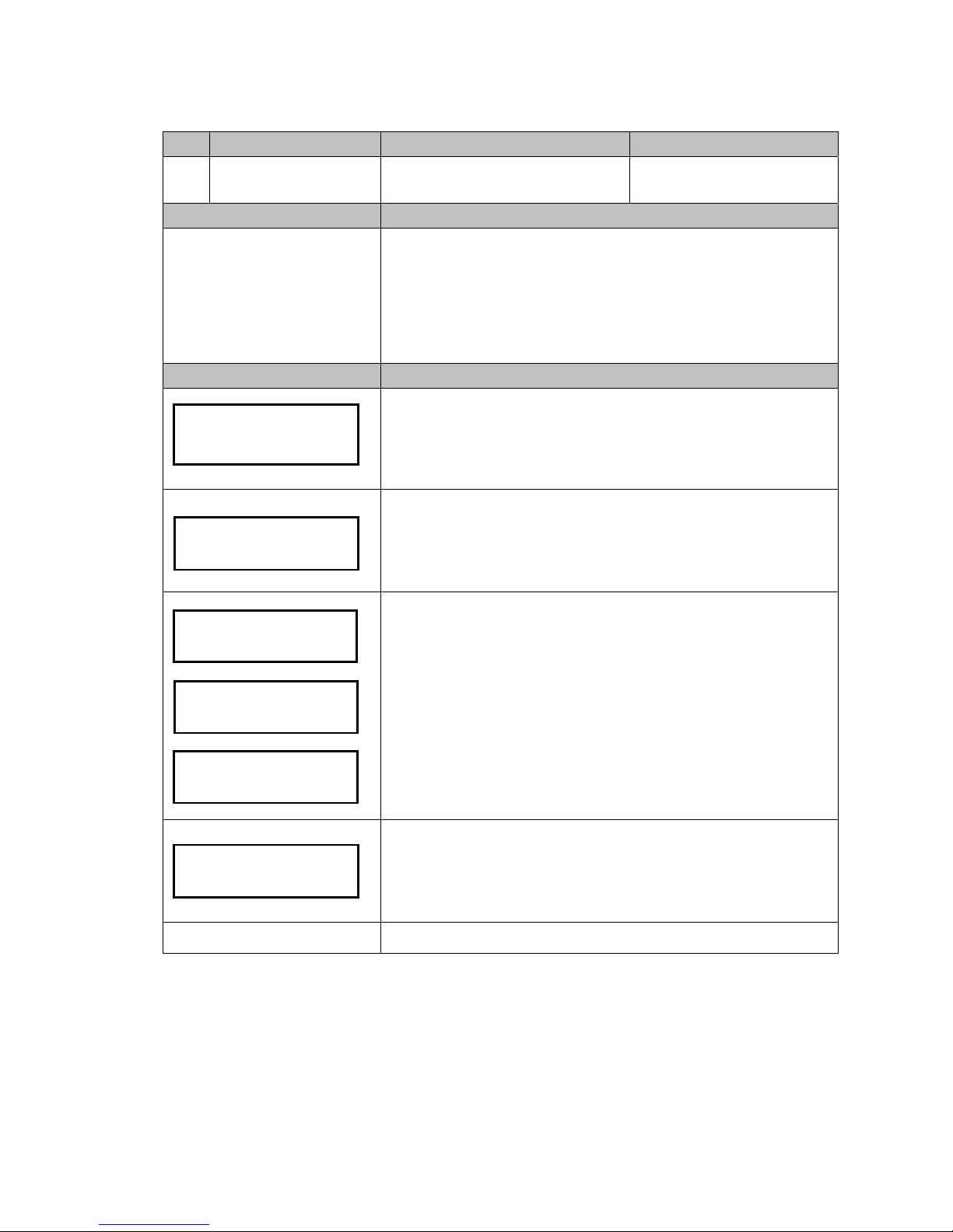
«
Motor Error:A
»
Code: E21
LED Light Display: None
LCM Display: As shown in figure below
Cause: The first motor group cannot be positioned. The first motor group might be
damaged, coin or foreign objects might have caused the motor to stuck, coins are stuck
in the coin tube, or the semicircle disk has derailed.
Corrective Measure: 1. Confirm whether a foreign object has caused the semicircle disk
to get stuck. If yes, remove the object and turn on the power
again. Use buttons A and B of the LCM to test and determine
whether the semicircle disk can be returned to its normal
position. If it does, then the machine has returned to its normal
operation.
2. Verify whether the semicircle disk has derailed. If yes, turn off
the power and remove the washer, then reinstall the disk back
onto the track and reactive the machine. Use buttons A and B of
the LCM to test and determine whether the semicircle disk can
be returned to its normal position. If it does, then the machine
has returned to normal operation.
Left Coin Jam
E21
Page 72

72
3. Turn on the power again and use buttons A and B of the
LCM to test and determine whether the semicircle disk can
be returned to its normal position. If it does, then the
machine has returned to normal operation. If nothing
happens, then the first motor group has been damaged.
Please notify the ICT personnel to handle the problem.
4. Verify whether the openings of the A and B tube has been
stuck by a coin. If a tube has been stuck, remove the stuck
coin, reassemble the coin tube, and turn on the power
again. Use buttons A and B of the LCM to test whether
tubes A and B can discharge coins correctly. If it does, then
the machine has returned to normal operation.
«
Motor Error:B
»
Code: E22
LED Light Display: None
LCM Display: As shown in figure
Cause: The second motor group cannot be positioned. The second motor group might
be damaged, coin or foreign objects might have caused the motor to stuck, coins are
stuck in the coin tube, or the semicircle disk has derailed.
Right Coin Jam
E22
Page 73

73
Corrective Measure: 1. Confirm whether a foreign object has caused an obstruction. If
yes, remove the object and turn on the power again and
determine if the coin rod can return back to its position. Use
buttons C, D, E, and F of the LCM to test and determine whether
the coin rod can hit the coin correctly.
If it does, then the machine has returned to normal operation.
2. Turn on the power again to observe whether the disk has
repositioned itself. If it does not, then the second motor group is
damaged. Please notify the ICT personnel for support.
3. Confirm whether the coin rod is stuck. If it is then manually
move the rod back to its position. Turn on the power again and
use buttons C, D, E, and F of the LCM to test whether the coin
rod can hit the coin correctly.
If it does, then the machine has returned to normal operation.
4. Confirm whether C, D, E, and F tube outlets are stuck by
coins. If yes, remove the coins and reinstall the tube cassette.
Turn on the power again and use buttons C, D, E, and F of the
LCM to test whether coins can be discharged correctly. If it does,
then the machine has returned to normal operation.
Page 74

74
«
Cassette Out
»
Code: E23
LED Light Display: 5 red
LCM Display: As shown in figure
Cause: Parts malfunction or coin tubes
have been incorrectly positioned.
Corrective Measure: Ensure that the
coin tubes are correctly positioned
Inhibit
Cassette Out E23
Page 75

75
«
Tube H/L Sensor Error
»
Code: E24
LED Light Display: 6 red+ 4 red
LCM Display: As shown in figure
Cause: Coins got stuck at the coin separation area or the coin tube opening twice in a
row, causing the HI Level Sensor to fail to detect the coin twice in a row.
Corrective Measure:
1. Open the LCM panel to verify whether coins are stuck in the coin
separation area. If yes, then push aside the transparent latch for the
coin guiding board, remove the coin guiding board, remove the stuck
coins, and then reinstall the coin guiding board. Turn on the power
again. Insert each denomination to ensure that it enters the
corresponding coin tube. If yes, then the problem has been resolved.
2. Ensure that the coin tubes have been positioned correctly.
Restart the power. Insert each denomination to ensure that it enters
the corresponding coin tube. If yes, then the problem has been
resolved.
Coin->Tube
Sensor Error E24
Page 76

76
«
Tube H/L Sensor Error:A
»
Code: E25
LED Light Display: None
LCM Display: As shown in figure below
Cause: Low Level = empty, Hi Level = full. Coin might be sorted to wrong tube.
Corrective Measure: Changer retries every 2 seconds during the standby mode.
Remove the stuck coin then restart changer to solve the problem.
«
Tube H/L Sensor Error:B
»
Code: E26
LED Light Display: None
LCM Display: As shown in figure below
Cause: Low Level = empty, Hi Level = full. Coin might be sorted to wrong tube.
Corrective Measure: Changer retries every 2 seconds during the standby mode.
Remove the stuck coin then restart changer to solve the problem.
«
Tube H/L Sensor Error:C
»
Code: E27
LED Light Display: None
LCM Display: As shown in figure below
Cause: Low Level = empty, Hi Level = full. Coin might be sorted to wrong tube.
Corrective Measure: Changer retries every 2 seconds during the standby mode.
Remove the stuck coin then restart changer to solve the problem.
Tube A Sensor
Error E25
Tube B Sensor
Error E26
Tube C Sensor
Error E27
Page 77

77
«
Tube H/L Sensor Error:D
»
Code: E28
LED Light Display: None
LCM Display: As shown in figure below
Cause: Low Level = empty, Hi Level = full. Coin might be sorted to wrong tube.
Corrective Measure: Changer retries every 2 seconds during the standby mode.
Remove the stuck coin then restart changer to solve the problem.
«
Tube H/L Sensor Error:E
»
Code: E29
LED Light Display: None
LCM Display: As shown in figure below
Cause: Low Level = empty, Hi Level = full. Coin might be sorted to wrong tube.
Corrective Measure: Changer retries every 2 seconds during the standby mode.
Remove the stuck coin then restart changer to solve the problem.
«
Tube H/L Sensor Error:F
»
Code: E30
LED Light Display: None
LCM Display: As shown in figure below
Cause: Low Level = empty, Hi Level = full. Coin might be sorted to wrong tube.
Corrective Measure: Changer retries every 2 seconds during the standby mode.
Remove the stuck coin then restart changer to solve the problem.
Tube D Sensor
Error E28
Tube E Sensor
Error E29
Tube F Sensor
Error E30
Page 78

78
«
Barcode Reader Error
»
Code: E31
LED Light Display: None
LCM Display: As shown in figure below. The machine will continue to work.
Cause: Barcode Reader error.
Corrective Measure: Ensure that the Barcode
Reader is not dirty or blocked by foreign objects.
If yes, then clean the Barcode Reader or remove
the obstruction.
Caution: The machine would continue to work
despite the Barcode Reader error.
«
Coin Size LED Error
»
Code: E32
LED Light Display: None
LCM Display: As shown in figure. The machine will continue to work.
Cause: The three sets of LEDs used to distinguish Coin size have been damaged.
Corrective Measure: Open the deck. Ensure that the Sensor and LED are not
dirty or blocked by foreign objects. If they are, then clean
the Sensor and LED or remove the obstruction. If the
problem cannot be solved, notify ICT personnel for support.
BarCode Sensor
Error E31
Diameter Sensor
Error E32
Page 79

79
«
Recosnition Version Error
»
Code: E33
LED Light Display: None
LCM Display: As shown in figure below.
Cause: Recosnition Module Damage
Corrective Measure: Notify the ICT personnel
«
Inhibit By VMC
»
Code: None
LED Light Display: 2 red
LCM Display: As shown in figure below
Cause: The “Inhibit” signal transmitted by the interface.
Corrective Measure: None.
Inhibit by
VMC
Recosnition Ver
Error E33
Page 80

80
8.
Firmware Download and Upgrade Instruction
Statement: This document is established and written purely for the convenience of the
customers. The document does not clearly specify the legal responsibilities
assumed by the International Currency Technologies (ICT) Corp. The ICT
Corp.
reserves all rights to the original records of legal writings and intellectual
properties, including subsequent modifications of the figures and updates of the
texts.
This Document is only Applicable to the Corresponding Coin Changer Products
This document provides detailed downloading and burning steps as follows:
8.1. MCU STM32 Firmware Download by FP-004
8.1.1.
Tools
Please prepare download box and related wire accessories ready
1. Tool Kit Box: FP-004 x 1pc
2. Cable-wires:
#WEL-RF303 x 1pc
#WEL-RCC42 x 1pc
8.1.2. Connection
Page 81

81
8.1.3. Start Download Process:
1. Please ensure that the RS232 connection from PC to FP-004 works properly; if not,
check whether RS-232 program and driver has been activated.
2. Click and execute FP4DT.exe
Figure.64
3. Select Coin Changer, STM8, type of FP004 download box, RS232 COM port, and
specify the path for file download (only accept files with .s19 extensions).
Figure.65
4. Select “Download”
5. Download provides two options, direct download to the
Coin Changer, or download and burn to the FP-004 control box.
Figure.66
Page 82

82
6. Select the download option then the process would execute automatically
(The left-bottom corner of the screen shows the communication status)
Figure.68
7. Download Completed, all procedures reach 100%.
Figure.69
Page 83

83
8.2. MCU STM32 Firmware Download by IrDA Special Function
8.2.1. Tools
Please prepare related accessories ready
1. PDA supports IrDA download
8.2.2. Connection
Please keep distance between changer and PDA within 5 cm, angle deviation less than
5 degree.
8.2.3. Start Download Process:
1. Turn on power and prepare changer in standby status.
2. Start download procedure of PDA to update firmware.
5 cm
Page 84

84
9.
PC Tool Instruction
To setup Changer through PC Tool, please prepare tools and connection as
following chapter instruction:
Chapter 8-1-1. Tools
Chapter 8-1-2. Connection
This document provides detailed PC setup steps as follows:
9.1. Cashfloat Setting
9.1.1.
Set Changer to Initial Setting
1. Open PC Tool. Select “Cashfloat Setting” function item.
2. Select changer Type.
3. Select tube setting from the list then PC tool will display the setting.
4. Click “Write Initial Setting” button to start download process.
5. To confirm whether the changer has been correctly setup, click “Read Setting From
CC” to load changer setting and display on PC tool for confirmation.
Page 85

85
9.1.2.
Set Changer to Customization Setting
1. Open PC Tool. Select “Cashfloat Setting” function item.
2. Select Changer Type.
3. Select tube setting from the list then PC tool will display the setting.
4. Modify the settings to customization configuration.
The setting items may vary depends on different region.
5. Click “Set Coin Changer” button to start download process.
6. To check whether the changer has been correctly setup, click “Read Setting From
CC” to load changer setting and display on PC tool for confirmation.
Page 86

86
9.1.3.
Set Coin Channels
Executive only
1. Open PC Tool. Select “Cashfloat Setting” function item.
2. Select Changer Type.
Channel setting function only applies to 6100E type.
3. Select tube setting from the list then PC tool will display the setting.
Click “Read Setting From CC” to load current changer channel setting for editing.
Channel setting list in the right bottom area for editing.
For price channel position, please see listed sequence as figure below.
Notice! Every block need to be filled price in before set to changer. If channel price is 0,
input 0 to blocks.
4. After filling channel price into list, click “Set Coin Changer” to save setting to changer.
1 2 3 4 5
6 7 8 9 10
11 12 …
Page 87

87
9.1.4.
Setup File Management
Import Setting File
1. Click “Import Setting File” to load setup file, a file selection window shows up.
2. Choose setup file in .ini format and click open to load.
3. PC Tool displays setting of the imported file.
User can then click “Set Coin Changer” to download or made setup modification.
Page 88

88
Save Setting File
1. Choose setting options to customized configuration for saving.
2. Click “Save Setting File” to save a setup file, a file saving window shows up.
3. Choose file path and input file name, and then click save to complete saving. Setup
file will be saved as an .ini file.
Page 89

89
9.2. Serial Number Setting
9.2.1. Set Serial Number
1. Open PC Tool. Select “Serial Number” function item.
2. To set serial number, Input serial number in blocks. The serial number in blocks will
be setting into changer.
Then click “Write” button to set serial number to changer.
“Setting Finish!” message shows up after setting finished. Click “OK” to close the
message.
3. To check serial number of the changer, click “Read” button to load.
Serial number will display in blocks.
Before loading further serial number, click “Clear label” button to clear numbers in blocks.
Notice:
Customer Number contains 16 digits and each digit applies to 0 - 9.
Machine Number contains 12 digits and each digit applies to 0 - 9 or A – Z.
Page 90

90
10.
Read Audit Data
This document provides detailed audit data read out steps as following methods:
Read audit data by ICT MTB
Read audit data by IrDA
10.1. Read Audit Data by ICT MTB
10.1.1.
Tools
Please prepare download box and related wire accessories ready
1. Tool Kit Box: MTB x 1pc
2. Cable-wires:
#WEL-RSB04 x 1pc
10.1.2. Connection
10.1.3. Start Read Audit Data by MTB
1. Prepare connection above and set changer in standby status for data read out.
2. Turn on MTB power and enter “Changer Operate” mode.
3. Select “Read Audit Data” to execute read out process, the .eva audit data will be
saved to SD card of MTB.
Then MTB request whether to clear audit data in changer? Choose Yes/No to determine
whether to clear audit data in changer.
4. Turn off MTB power before disconnection from MTB to Changer. Remove SD card
from MTB to read out .eva file from PC.
*For detail MTB Instruction, please refer to MTB Manual.
Page 91

91
10.2. Read Audit Data by IrDA
To read audit data by IrDA, please prepare tools and connection as following chapter
instruction:
Chapter 8-2-1. Tools
Chapter 8-2-2. Connection
1. Prepare connection above and set changer in standby status for data read out.
2. Use PDA IrDA component to point directly to the IrDA of changer.
3. Start audit data transmission. A file format in .eva will be saved to PDA.
Notice! If audit data has been successfully read out, the audit data in changer would be
automatically cleared, but not include serial numbers.
Page 92

92
11.
Module Assembling Procedure
11.1. Upper Module Disassembling:
1. Press down the shell
stabilization leaver until the
fixed axis is fully exposed.
2. Pull and rotate the
upper half of the module
forward.
3. After the upper half of
the module is pulled out,
unplug the soft gray cable,
and then lift upward at a
35 degree angle until the
end.
4. Pull the upper half of the module out of
the shell.
Page 93

93
11.2. Recognition Module Disassembling:
1. Turn the upper half of the module
towards the back and ensure that the
two fix points of the modules are
flipped to the two sides.
2. Pull out the recognition module.
3. Unplug the wire connecting to the
identification module.
4. Pull and remove the recognition module.
Page 94

94
11.3. Coin Discharge Module Disassembling:
1. Remove the two screws on the sides of the
coin discharge module.
2. Rotate the coin discharge module downward
90 degrees.
3. Unplug the wire connecting to the coin
discharge module.
4. Pull and remove the coin discharge module.
Page 95

95
12.
Module Exploded Views(CC6100-TWD)
Note Order
Part Number
Appellation
Quantity
1
3RCC-CAS05001
Coin Change Main Machine Module
1
2
3RCC-POK19000
Coin Changer-Coin Discharge Module
1
3 3RCC-MOT02001
Changer Coin Discharge Motor Module
1
4 3RCC-IDE11002
Recognition Module (2.5mm)
1
5
3RCC-SOR11006
Coin Separation Module (ESCROW-A)
1
6
3RCC-TUB25004
Coin Tube Module (TWD Version-2)
1
7
3RCC-FAC01002
LCM Display Panel Module
1
Page 96

96
Taiwan
International Currency Technologies Corporation
No. 28, Lane 15, Sec. 6, Minquan E. Rd., Neihu Dist., Taipei City 114, Taiwan(R.O.C.)
Tel: 886-2-2793-1236 ‧ Fax: 886-2-2793-6125
sales@ictgroup.com.tw (For Sales)
‧
rma@ictgroup.com.tw (For Customer Service)
Website: www.ictgroup.com.tw
Page 97

97
www.ictgroup.com.tw
©
2017 International Currency Technologies Corporation
V. 1.9 Part Number: Beta 2017/08/24
 Loading...