

ICT AN-9 Datasheet

ANACHIP AN-9
Page 1
Anachip USA, Inc. • 780 Montague Expressway, Suit e #201, San Jos e, CA 95131
Tel: (408) 321-9600 • Fax: (408) 321-9696
www.anachi
p
.com
GRAY CODE COUNTER USING CLOCK DOUBLED INPUT
Anachip zero power PEEL™ devices extend the
applications of SPLD’s by offering p-term clock with clock
polarity feature. This allows designers to employ clocking
schemes using an internal node, without sacrificing an
output pin and logic function. Any pin, or p-term logic
equation, (an equation based only on AND terms) can be
used as a clock. An OR equation can be converted to
AND’s by applying DeMorgan’s theorem and setting the
clock polarity feature.
The following design example uses the product-term clock
feature of the Anachip PEEL™ 22LV10 to clock a low
power gray code counter with a frequency doubler feature.
The frequency doubler is generated using a “one shot” that
creates a pulse during both the rising and falling input
system clock edges. These pulses are used as the clock
source for the gray code counter. Using this clocking
scheme, the output of counters, shift registers and state
machines in peripheral or remote systems can be
transmitted at one data bit per clock edge of the incoming
system clock. Both of Anachip’s 3V devices, the
PEEL18LV8 and PEEL22LV10 feature Schmitt triggers on
all inputs including the clock input. These Schmitt trigger
inputs are recommended when encountering slow rise time
signals such slow clocks like the 32,768 hz oscil lator or the
R/C feedback of the PLD “one shot” used in this design
example.
SOURCE CODE
MACRO’S
A1 = Q0
A2 = Q1*!Q0
A3 = Q2*!Q1*!Q0
A4 = Q3*!Q2*!Q1*!Q0
A5 = Q4*!Q3*!Q2*!Q1*!Q0
A6 = Q5*!Q4*!Q3*!Q2*!Q1*!Q0
EQUATIONS
“Clock doubler operation (CS, internal p-term clock node)
“ ‘one shot’ triggers on rising edge of CLK, setting the latch X3.com
“X3 XOR’d with CLK in X2.com “to trigger ‘one shot’ again on the falling edge of “CLK. X3 is reset when CS = 1 and
CLK = 0, ready for the next rising edge
CS = !X1*X2
X2.OE = !X2
X2.Com = !RST*( (CLK$X3) + !X1*X2)
X3.Com = !RST*(CLK*(!X1*X2) + CLK*X3 + !(!X1*X2)*X3)
Q0 = !X4$Q2$Q1
Q1 = !A1*Q1 + A1*(!X4$Q2)
Q2 = !A2*Q2 + A2*(!X4)
Q3 = !A3*Q3 + A3*(!Q6$Q5$Q4)
Q4 = !A4*Q4 + A4*(!Q6$Q5)
Q5 = !A5*Q5 + A5*(!Q6)
Q6 = !A6*Q6 + A6* Q5
X4.Com = Q6$Q5$Q4$Q3
Gray Code Counter Using Clock Doubled Input (continued) Page 2
Anachip USA, Inc. • 780 Montague Expressway, Suit e #201, San Jos e, CA 95131
Tel: (408) 321-9600 • Fax: (408) 321-9696
www.anachi
p
.com
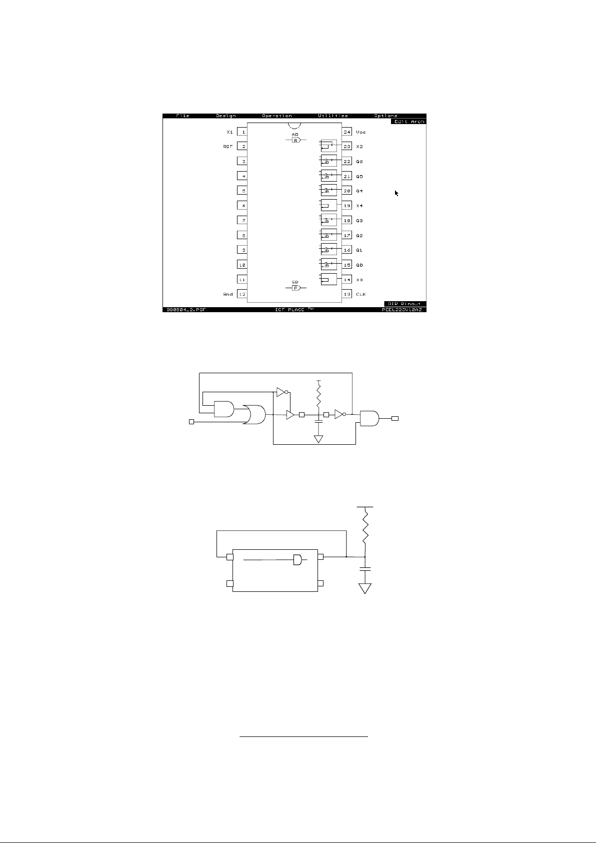
FIGURE 1.
Gray Code counter with frequency doubler pin block diagram.
FIGURE 2
Schematic of the PEEL™ “one shot”
FIGURE 3
PEEL™ “one shot” uses four pins. If the “one shot” is needed as a clock, the internal p-term clock node can be used instead of
an output pin. All zero power PEEL™ devices offer p-term clock with clock polarity feature.
PEEL Equations: X2: Combinational Positive I/O, SUM Feedback
OUT: p-term clock
X2.COM = IN + X2 * !X1
X2.OE = !X2
CS.COM = X2 * !X1 (equation p-term clock)
U1
U2
U3
R
C
X2 X1
CLK
CS
X2
R
C
X1
PEEL22LV10AZ
P-TERM CLOCK "CS"
CLK
 Loading...