

Page 1
Bill Validator
Installation Guide
2003 International Currency Technologies Corporation
Vol. 8.0 Part Number : H4458G-R
International Currency Technologies Corp.
Page 2

Use of Materials Limitations
International Currency Technologies Corporation (ICT) all rights reserved.
All materials contained are the copyrighted property of ICT.
All trademarks, service marks, and trade names are proprietary to ICT.
ICT reserves the right at all times to disclose or to modify any information as
ICT deems necessary to satisfy any applicable law, regulation, legal process
or governmental request, or to edit, refuse to post or to remove any information
or materials, in whole or in part, in ICT's sole discretion.
Contents
1. Introduction ............................................................................1
1-1. Overview ..........................................................................1
1-2. Features ...........................................................................1
2. Specifications ........................................................................1
Common .................................................................................1
Electrical .................................................................................1
Mechanical ..............................................................................1
3. Packing List ...........................................................................2
4. Dimension .............................................................................2
5. Installation .............................................................................3
5-1. Harness Application .........................................................3
5-1-1. I/O Circuit ................................................................14
5-2. DIP Switch Setting .........................................................17
5-3. Software Download and Upgrade ..................................17
6. Maintenance ........................................................................18
7. Trouble Shooting .................................................................19
Page 3
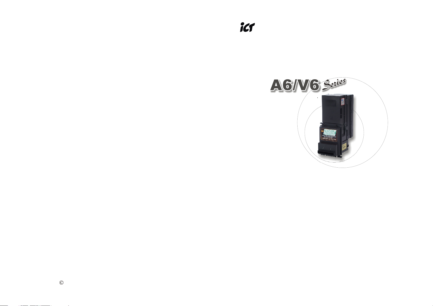
Series
A6/V6A6/V6
SeriesSeries
1. Introduction
1-1. Overview
A6/V6 Series is a bill acceptor which features not only high-security
module with bill box but also outstanding recognition, acceptance
rate up to 96% or even greater.
1-2. Features
Four way bill insertion acceptance.
Auto-calibrating.
Numerous interfaces available.
Easily Install & Maintain.
2. Specifications
Common
Acceptance Rate
96% or greater
Identification Time
Approx. 3 seconds
(From bill insert to stack.)
Electrical
Power Source
A6: 12V DC± 5%
117V AC±10%
V6: 34V DC± 5%
Power Consumption
50 watts maximum
Interface
A6: STD Pulse, 5V Enable
ICT Protocol
V6: MDB
Bill Insertion
Four-way acceptance
Operation Environment
Operation Temperature: 0°C~55°C
Storage Temperature: -30°C~70°C
Humidity: 30%~85RH
(no condensation)
3. Packing List
Main Accessory
Bill Acceptor
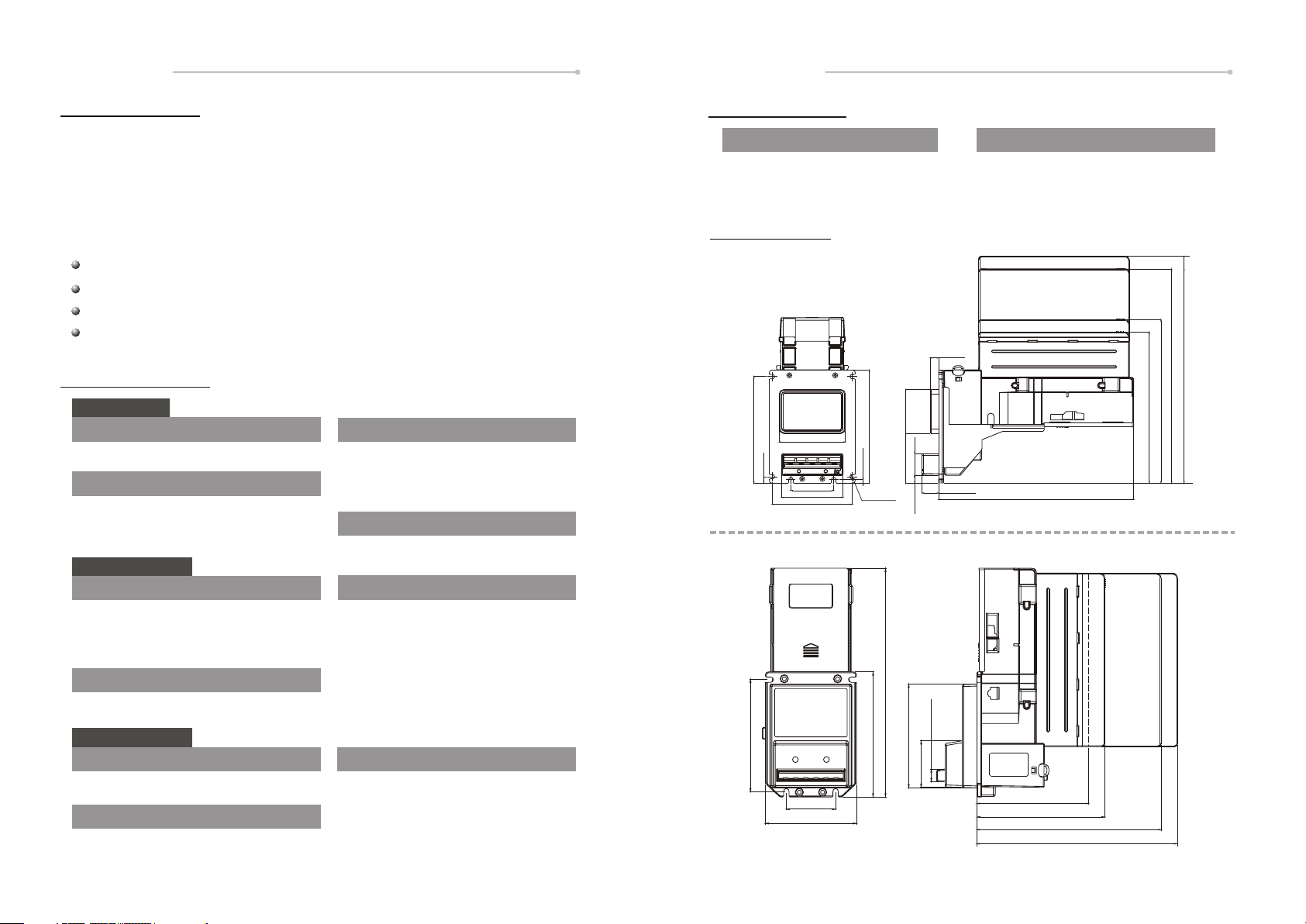
4. Dimension
tHorizontal
78.5[3.091]
126.5[4.980]
7.5[0.295]
51.0[2.008]
73.0[2.874]
95.0[3.740]
tVertical
134.0[5.276]
4.0[0.157]
6-R2.65
[R0.104]
10.0[0.394]
52.0[2.047]
26.0 [1.024]
59.0[2.323]
19.6[0.772]
9.0[0.354]
235.9[9.29]
Harnesses: see Page.3
A6/V6 Installation Guide
A6/V6 DIP Switch Setting Guide
1000P
800P
500P
300P
232.0[9.134]
500P
300P
179.5 [7.067] 300 bill
194.5 [7.657] 500 bill
254.5 [10.02] 800 bill
296.5 [11.67] 1000 bill
Unit : :mm [inch]
800P
1000P
Mechanical
Outline Dimension
See Page.2
Weight
Approx. 2kg (shipping)
Bill Capacity
Approx. 300 bills ( 200~ 300)
500 bills ( 300~ 500)
800 bills ( 750~ 850)
1000 bills (1000~1140)
- 1 -
13.0[0.51]
115.0[4.53]
50.8[2.00]
94.0[3.70]
107.0[4.21]
129.0[5.08]
48.1[1.90]
115.0[4.53] 300 bills
130.0[5.12] 500 bills
190.0[7.48] 800 bills
232.0[9.13] 1000 bills
Unit : :mm [inch]
- 2 -
Page 4
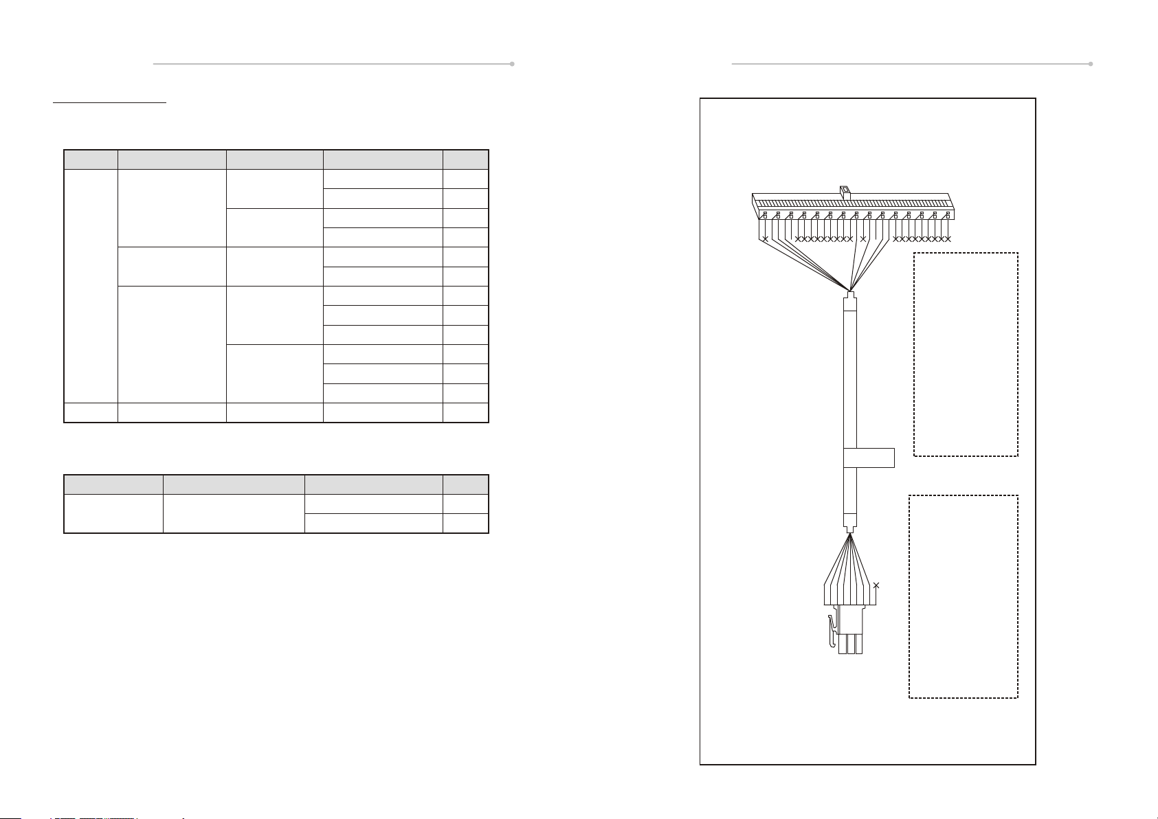
5. Installation
5-1. Harness Application
Bill Acceptor:
Interface Mode
STD Pulse
5V ENABLE
A6
RS232 for
ICT Protocol
V6
Programmer (Refer to 5-3):
Model
FP-001
MDB
Function
Download & Upgrade
Used Voltage
117V AC
12V DC
117V AC
12V DC
117V AC
34V DC
Cable No.
WEL-RM008
WEL-RM012
WEL-RM007
CU-R961-1
WEL-RM017
WEL-RM018
WEL-RM007
CU-R961-1
WEL-RV706
WEL-RM008
WEL-RM012
WEL-RV706
WEL-RM006
Harness
WEL-RM009
WEL-R087
Page
4
5
6
7
8
9
6
7
10
4
5
10
11
Page
12
13
A6/V6A6/V6
SeriesSeriesSeries
123456789
*
101112131415161718192021222324252627282930
2464 22 AWG 8C CABLE
AC 117V
WEL-RM008
*
BLK-15*2(KEY)
Pin 1- PURPLE......CREDIT_RELAY(Common)
Pin 3- RED..........................NEUTRALENABLE
Pin 4- WHITE..........117VACNEUTRAL(Power)
Pin 5- YELLOW....................NEUTRALINHIBIT
Pin 16- BLUE..................CREDIT_RELAY(N.O.)
Pin 18- BROWN.............................HOTENABLE
Pin 20- BLACK...................117VACHOT(Power)
Pin 21- GREEN........................EARTHGROUND
WEL-RM008
- 3 -
( STD Pulse, RS232<ICT Protocol> for 117V AC)
123456789
AMP 172340-1
Pin 1- YELLOW.....................NEUTRAL INHIBIT
Pin 2- RED...........................NEUTRALE NABLE
Pin 3- BROWN..............................HOT ENABLE
Pin 4- BLACK.....................117VAC HOT(Power)
Pin 5- GREEN................................Earth-Ground
Pin 6- WHITE...........117VAC NEUTRAL(Power)
Pin 7- BLUE.....................CREDIT_RELAY(N.O.)
Pin 8- PURPLE.........CREDIT_RELAY(Common)
Pin 9- Reserved
- 4 -
Page 5

A6/V6A6/V6
SeriesSeriesSeries
123456789
PURPLE.......CREDIT_RELAY (Common)
BLUE...................CREDIT_RELAY (N.O.)
GREEN.............................Earth - Ground
ORANGE...........................HOT ENABLE
RED..........................NEUTRAL INHIBIT-
YELLOW..................NEUARAL INHIBIT+
202
202
202
202
WEL-RM012
AC
202
202
WEL-RM007
101112131415161718192021222324252627282930
*
*
2464 22 AWG 8C CABLE
DC +12V
WEL-RM007
BLK-15*2(KEY)
Pin 1- PURPLE.......CREDIT_RELAY (Common)
Pin 2- RED..................................12VDC (Power)
Pin 3- WHITE........................................ENABLE-
Pin 5- YELLOW....................................INHIBIT+
Pin 10- BROWN...............................GND (Power)
Pin 16- BLUE...................CREDIT_RELAY (N.O.)
Pin 18- BLACK......................................ENABLE+
Pin 20- GREEN.......................................INHIBIT-
2464 22 AWG 6C CABLE
AC 117V
WEL-RM012
123456789
( STD Pulse, RS232<ICT Protocol> for 117V AC)
( STD Pulse, RS232<ICT Protocol> for 12V DC)
123456789
AMP 172340-1
Pin 1- YELLOW...............NEUTRAL INHIBIT+
Pin 2- RED.......................NEUTRAL INHIBIT-
Pin 3- ORANGE........................HOT ENABLE
Pin 4- BLACK...............117VAC HOT (Power)
Pin 5- GREEN..........................Earth - Ground
Pin 6- BLACK......117VAC NEUTRAL (Power)
Pin 7- BLUE...............CREDIT_RELAY (N.O.)
Pin 8- PURPLE...CREDIT_RELAY (Common)
Pin 9- Reserved
Pin 1- YELLOW.......................................INHIBIT+
Pin 2- GREEN..........................................INHIBIT-
Pin 3- Reserved
Pin 4- Reserved
Pin 5- RED...................................12V DC (Power)
Pin 5 Dotted- BLACK..................12V DC (Power)
Pin 6- Reserved
Pin 7- BLUE......................CREDIT_RELAY (N.O.)
Pin 8- PURPLE..........CREDIT_RELAY (Common)
Pin 9- BROWN..................................GND (Power)
Pin 9 Dotted- WHITE.......................GND (Power)
AMP 172340-1
- 6 -- 5 -
Page 6

A6/V6A6/V6
202
202
202
202
202
202
SeriesSeriesSeries
123456789
161718192021222324252627282930
HORN-30
*
2464 22 AWG 6C CABLE
CU-R961-1
DC 12V
#CU-R961-1
PIN 1- YELLOW...........................INHIBIT+
PIN 2- GREEN..............................INHIBIT-
PIN 5- RED...............+12VDC(POWER-IN)
PIN 7- BLUE...............CREDIT-RELAY-NO
PIN 8- PURPLE.......CREDIT-RELAY-COM
PIN 9- ORANGE.............GND(POWER-IN)
(5V ENABLE)
WEL-RM017
123456789
1011121314
*
2464 22AWG 8C CABLE
A6&A7 AC110V 5V INHIBIT
#WEL-RM017
15
PIN 1- PURPLE.........................CREDIT-RELAY-COM
PIN 4- WHITE............115VAC-NEUTRAL(POWER IN)
PIN 5- YELLOW..............................NEUTRAL-INHIBIT
PIN 10- BROWN......................................................GND
PIN 16- BLUE.................................CREDIT-RELAY-NO
PIN 20- BLACK.....................115VAC-HOT(POWER IN)
PIN 21- GREEN..................................EARTH-GROUND
PIN 27.& 28. & 29- RED..............................I-ENABLE-L
PIN 13. & 14. & 15. & 25- BLACK...............I-ENABLE-H
( STD Pulse, RS232<ICT Protocol> for 12V DC)
PIN 2- RED....................................................I-ENABLE-L
PIN 4- BLACK.............................................115VAC-HOT
PIN 5- GREEN.....................................EARTH-GROUND
PIN 6- WHITE & YELLOW.................115VAC-NEUTRAL
PIN 7- BLUE.....................................CREDIT-RELAY-NO
PIN 8- PURPLE & BROWN...........CREDIT-RELAY-COM
.551 inch or 14mm
456
789
+AMP
.165inch or 4.2mm
AMP 172340-1 BACK VIEW
123456789
.551 inch or 14mm
K
1 2 3
4 5 6
7 8 9
+AMP
AMP 172332-1
AMP 172332-1 BACK VIEW
.165inch or 4.2mm
AMP 172340-1
123
- 8 -- 7 -
Page 7

A6/V6A6/V6
AC
202
202
202
202
(KST)
(SHBM1-4)
SeriesSeriesSeries
Pin 1- BLUE................GND
Pin 2- YELLOW.........TX22
Pin 3- GREEN...........RX22
Pin 5- Reserved
Pin 6- Reserved
Pin 6- RED..................VCC
Pin 7- BLACK.............RX11
Pin 8- WHITE..............TX11
8
7
6
5
4
3
2
1
RJ-45
RJ-45 VIEW
2464 22 AWG 6C CABLE
A6&A7 AC110V 5V INHIBIT
(5V ENABLE)
WEL-RM018
#WEL-RM018
WEL-RV706
26 AWG 6C PHONE CABLE
ICT PROTOCOL
WEL-RV706
(RS232 for ICT Protocol )
123456789
PIN 2- RED.............................................I-ENABLE-L
PIN 4- BLACK..................115VAC-HOT(POWER-IN)
PIN 5- GREEN..............................EARTH-GROUND
PIN 6- BLACK........115VAC-NEUTRAL(POWER-IN)
PIN 7- BLUE..............................CREDIT-RELAY-NO
PIN 8- PURPLE......................CREDIT-RELAY-COM
12345
6789
D-SUB(F)
.551 inch or 14mm
1 2 3
+AMP
K
4 5 6
7 8 9
.165inch or 4.2mm
AMP 172332-1 BACK VIEW
Pin 1- Reserved
Pin 2- RXD
Pin 3- TXD
Pin 4- Reserved
Pin 5- GND
Pin 6- Reserved
AMP 172332-1
D-SUB 9F TOP VIEW
Pin 7- Reserved
Pin 8- Reserved
Pin 9- Reserved
- 10 -- 9 -
Page 8

123456789
HORN-30
161718192021222324252627282930
*
1011121314
*
DC 34V MDB
#WEL-M006
A6/V6A6/V6
15
Pin 6- ORANGE...........................Master Receive
Pin 14- RED..................................Master Transmit
Pin 16- YELLOW..................34VDC Power Return
Pin 23- 3BLUE...............................................4VDC
Pin 28- GREEN.............Communications Common
SeriesSeriesSeries
PIN 8- BROWN...........TX1
PIN 7- BLUE...............RX1
PIN 6- YELLOW.........VCC
PIN 5- GREEN.........../RET
PIN 4- RED............./PROG
PIN 3- BLACK.............RX2
PIN 2- ORANGE..........TX2
PIN 1- GRAY..............GND
8
7
6
5
4
3
2
PCB JACK TOP VIEW
1
PCB JACK VIEW
WEL-RM006
( MDB for 34V DC )
12345
12345
6
MOLEX 5557-6R
6
Pin 1- BLUE..............................................34VDC
Pin 2- YELLOW.................34VDC Power Return
Pin 3- N/C
Pin 4- ORANGE...........................Master Receive
Pin 5- RED..................................Master Transmit
MOLEX 5559-06P
Pin 6- GREEN............Communications Common
WEL-RM009
DOWNLOAD LINE
#WEL-M009
PIN 1- GRAY..............GND
PIN 2- ORANGE..........TX2
PIN 3- BLACK.............RX2
PIN 4- RED............./PROG
PIN 5- GREEN.........../RET
PIN 6- YELLOW.........VCC
PIN 7- BLUE...............RX1
PIN 8- BROWN...........TX1
8
7
6
5
4
3
2
1
PCB JACK TOP VIEW
PCB JACK VIEW
123
456
54 6
1 2 3
.163inch or 4.14 mm
MOLEX 5557-6R BACK VIEW
.163or4.14
MOLEX 5559-06P BACK VIEW
- 12 -- 11 -
Page 9

A6/V6A6/V6
SeriesSeriesSeries
5-1-1. I/O Circuit
Pulse
+5VDC
Credit O/P
PIN 1- BROWN
PIN 2- RED.................TX
PIN 3- ORANGE.........RX
PIN 4- YELLOW
PIN 5- GREEN.........GND
PIN 6- BLUE
PIN 7- PURPLE
PIN 8- GRAY
PIN 9- BLACK
Bill Acceptor
+5VDC
6 7 8 9
1 2 3 4 5
D-SUB 9M TOP VIEW
Inhibit I/P
Bill Acceptor
+5VDC~+12VDC
4K7
Credit_Relay_NO
Credit_Relay_COM
Customer Side
+5VDC~+12VDC
1K
Inhibit+
Inhibit-
Hi"TR ON
Lo"TR OFF
TR
Customer Side
WEL-R087
ICT-Protocol
+5VDC
PIN 1- BROWN
PIN 2- RED.................TX
PIN 3- ORANGE.........RX
PIN 4- YELLOW
PIN 5- GREEN.........GND
PIN 6- BLUE
PIN 7- PURPLE
PIN 8- GRAY
PIN 9- BLACK
TXD
TXD
+5VDC~+12VDC
1K
RXD
12345
6789
D-SUB 9F D-SUB 9M
D-SUB 9F TOP VIEW
Bill Acceptor
RXD
+5VDC
RXD
TXD
Bill Acceptor
- 13 - - 14 -
Customer Side
Hi"TR ON
Lo"TR OFF
Customer Side
Page 10
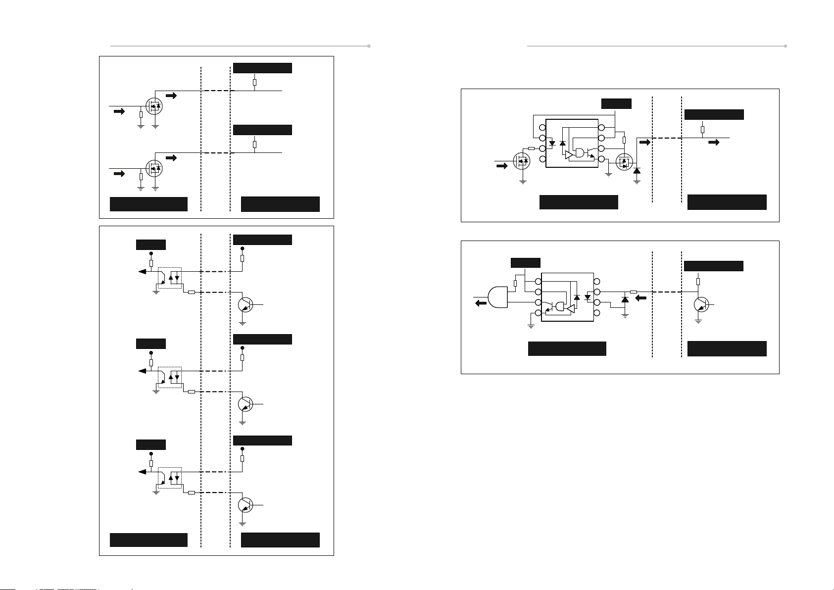
5V Enable
A6/V6A6/V6
SeriesSeriesSeries
+5VDC~+12VDC
2_CREDIT
2
1K
MDB
+5VDC
+5VDC~+12VDC
+5VDC~+12VDC
5_CREDIT
5
1K
TXD
1
2
3
4
8
7
6
5
MDB_MASTER_RXD
1K
Bill Acceptor
+5VDC
1_ENABLE
+5VDC
2_ENABLE
+5VDC
5_ENABLE
Customer Side
+5VDC~+12VDC
1K
1_ENABLE_H
1_ENABLE_L
HiZTR ON
LoZTR OFF
TR
+5VDC~+12VDC
1K
2_ENABLE_H
2_ENABLE_L
HiZTR ON
LoZTR OFF
TR
+5VDC~+12VDC
1K
5_ENABLE_H
RXD
+5VDC
Bill Acceptor
8
7
6
5
Bill Acceptor
Customer Side
+5VDC~+12VDC
1
2
3
4
MDB_MASTER_TXD
1K
HiZTR ON
LoZTR OFF
Customer Side
Bill Acceptor
5_ENABLE_L
HiZTR ON
LoZTR OFF
TR
Customer Side
- 15 - - 16 -
Page 11

5 4 3 2 1
9 8 7 6
1 2 3 4
ON DIP
A6/V6A6/V6
SeriesSeriesSeries
5-2. DIP Switch Setting
There are two serial DIP switches which are located on the side of A6/V6
Series (as figure 1). According to different currencies which are used by
users, DIP switch settings could be varied to fit users’ need.
Besides, there’s also a serial DIP switches on CPU board inside of A6/V6
Series for interface settings.(as figure 2)
Please refer to “A6/V6 Series DIP Switch Setting” Guide in the package for
more detail.
figure 1
figure 2
5-3. Software Download and Upgrade
To download and upgrade the software to A6/V6 Series, the programmer
(FP-001) is needed. Please contact ICT to purchase FP-001 and refer to
FP-001 user guide for software download and upgrade information.
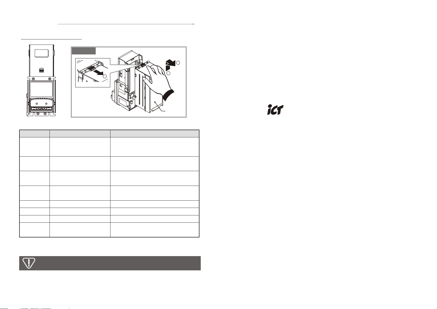
6. Maintenance
To make sure the bill acceptor always works smoothly, please clean the
internal parts every two weeks to every two months.
To clean the internal parts:
1. Press the buttons on the sides of bill path unit and pull the unit out.
Buttons
2. Use a soft, dry cloth or towel to clean the bill path and sensors.
Sensors
PH
COM1 or COM2
PC
FirmwarePower
A6/V6
FP-001
WEL-RM009 (see page. 12)WEL-087 (see page. 13)
Power must be applied to BA AFTER connecting.
Do not use an organic solvent such as gasoline or paint thinner
Sensors
to clean the unit.
- 17 - - 18 -
Page 12
A6/V6
7. Trouble Shooting
SeriesSeries
figure 3
3
Bezel LED
LED Flashes
1
3
3+2
3+5
(Optional)
2
5
6
7
1
Release Button
Status Corrective Actions
Bill jammed.
Recognition sensor error.
Hook sensor error.
Out sensor error.
Disable
Bill box has been removed.
Stacker error or stacker full.
Motor error.
2
Bill Box
Remove the bill box by sliding the top
button and the bill path unit (as figure 3),
and then remove the jammed bill.
Inspect for foreign objects on sensor
or bill path and clean.
Inspect for foreign objects on security
hook and clean.
Inspect for foreign objects on sensor
or bill path and clean.
Inspect for right DIP switch setting.
Replace the bill box.
Empty the bill box.
Inspect for foreign objects on bill path
and clean.
Taiwan
International Currency Technologies Corporation
Ji-Hong Building, No 24, Alley 38, Lane 91, Nei-hu Rd., Sec. 1,
TaiPei, Taiwan, R.O.C.
Tel: 886-2-2797-1238 Fax:886-2-2797-1634
sales@ictgroup.com.tw ( For Sales )
rma@ictgroup.com.tw ( For Customer service )
Website:www.ictgroup.com.tw
If the error can not be solved after corrective actions or happen again,
please contact ICT for technical support.
- 19 -
 Loading...