

Page 1
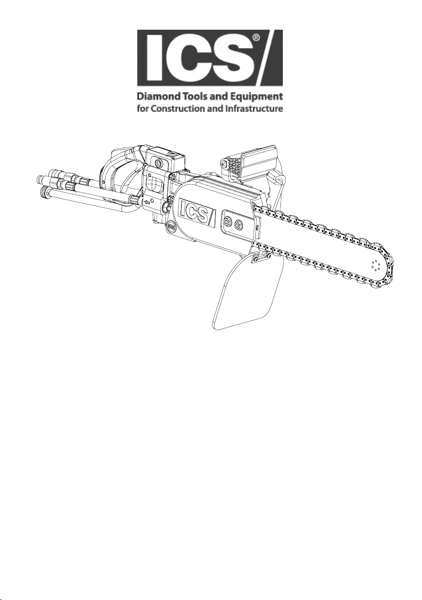
890F4
OPERATOR MANUAL
WARNING: READ AND UNDERSTAND ALL SAFETY WARNINGS
AND ALL INSTRUCTIONS BEFORE YOU USE THIS EQUIPMENT.
Failure to follow the warnings and instructions may result in re, serious injury, or death.
SAVE ALL WARNINGS AND INSTRUCTIONS FOR FUTURE REFERENCE
© 2018 ICS®, Blount International Inc. REV07192018 P/N 566594
Page 2

Introduction
890F4 OPERATOR MANUAL
INTRODUCTION
The 890 power cutter is designed to cut concrete, stone, and masonry when
used with the appropriate genuine ICS Diamond Chain. Ductile iron pipe may
also be cut but ONLY if using PowerGrit® Utility Chain. This is a professional
tool and is solely intended for use by trained and experienced operators. A rst
ENGLISH
time operator should obtain practical instruction before using the power cutter,
as well as reading and understanding this Operator’s Manual.
Local legislation and/or workplace standards may regulate the use of this
power cutter. Determine what regulations are applicable in the place you work
before using the power cutter.
This instruction manual contains translations of a manual drafted in English
and are provided to assist those who do not speak English as their rst
language. Being a technical writing, some terms may not have a like or
equivalent meaning as translated. Therefore, you should not rely on this
translation, and should cross-reference the English version, where relying on
the translated instructions could result in harm to your person or property.
Specications subject to change without notice. For most up-to-date
version of this manual, please visit:
https://icsdiamondtools.com/customer-service-support/.
TABLE OF CONTENTS
SAFETY RULES
SYMBOLS AND LABELS
ICS 890F4 NAMES AND TERMS
PRODUCT IDENTIFICATION
UNPACKING AND ASSEMBLY
OPERATION
MAINTENANCE
TROUBLESHOOTING
TECHNICAL SPECIFICATIONS
SERVICE CENTERS
© 2018 ICS®, Blount International Inc. REV07192018 P/N 566594
2
4
8
10
12
14
21
29
33
34
35
Page 3

890F4 OPERATOR MANUAL
EC‐DECLARATIONOFCONFORMITY
BLOUNTINTERNATIONALINC.DECLARESUNDEROURSOLERESPONSIBILITYTHATTHEFOLLOWINGPRODUCTS:
_____________________________________________ ________________________________________________________ _________________
Brand: ICS
ProductType: HydraulicCut‐offmachineequippedwithdiamondsawchain
Model: 890F4,890F4‐FL
_____________________________________________ ________________________________________________________ _________________
ARECOMPLIANTWITHTHEFOLLOWINGAPPLICABLEEUROPEANDIRECTIVESANDSTANDARDS:
MachineryDirective(MD)2006/42/EC
ENISO12100‐1,‐2:2009
ENISO5349‐1,‐2:2001
ENISO3744:2009
_____________________________________________ ________________________________________________________ _________________
TECHNICALDOCUMENTATIONFILE,LOCATIONANDCONTACT:
ISO10726:1992
BlountInternational,Inc.
4909SEInternationalWay
Portland,Oregon97222,USA
Forproductcomplianceinquiries,sendrequesttoproductcompliance@blount.com
AuthorizedRepresentative: ChristopherSewardPE
AuthorizedSignature:
Title: Director:ProductSafety&Compliance
PlaceIssued: Portland,OregonUSA
DateOriginallyIssued: 26November,2013
DateRevised: 13November,2017
4909 SE INTERNATIONAL WAY | PORTLAND, OREGON 97222-4601
© 2018 ICS®, Blount International Inc. REV07192018 P/N 566594
3
Page 4
Safety Rules
890F4 OPERATOR MANUAL
SAFETY RULES
To get the maximum benet from your power cutter, and assure maximum
safety, be sure to read this manual thoroughly and follow the safety instructions
ENGLISH
provided.
EXPLANATION OF WARNING LEVELS
DANGER
Indicates a hazard with a high level of risk which, if not avoided, will result in
death or serious injury.
WARNING
Indicates a hazard with a medium level of risk which, if not avoided, could result
in death or serious injury.
CAUTION
Indicates a hazard with a low level of risk which, if not avoided, could result in
minor or moderate injury.
IMPORTANT
Indicates a potential situation exists which, if not avoided, may result in damage
to your power cutter or property.
© 2018 ICS®, Blount International Inc. REV07192018 P/N 566594
4
Page 5
890F4 OPERATOR MANUAL
Safety Rules
HANDLING HYDRAULIC FLUID SAFELY
WARNING
Hydraulic uid is combustible or can become combustible.
Consult the SDS (Safety Data Sheet) for the hydraulic uid being used for
ash point and auto ignition temperature ranges. When these uids discharge
under pressure in a ne mist, they ignite easily, burn rapidly, and emit large
quantities of heat. In fact, their heats of combustion, which are over 18,000
BTU/lb (2327 kJ/kg), are comparable to fuel oil.
CAUTION
Check for hydraulic leaks before starting the hydraulic power source.
Visually check for leaks from the hydraulic ttings, and lines and do not use if
any leaks are found.
WORK AREA SAFETY
Following are the basic instructions for work area safety.
WARNING
Drugs or alcohol can impair vision, dexterity, and judgment.
Do not operate the power cutter when tired or under the inuence of
any substance.
Do not operate this product during severe inclement weather.
CAUTION
Remove or control slurry to prevent slippery conditions while cutting.
This power cutter uses water and can cause slippery surfaces due to the slurry
produced and/or freezing temperatures.
Keep bystanders away from work area.
Set up a well-marked safety zone with a roped boundary and clear signs to
keep bystanders at least 6 m (20 ft) away.
© 2018 ICS®, Blount International Inc. REV07192018 P/N 566594
5
Page 6
Safety Rules
890F4 OPERATOR MANUAL
PERSONAL SAFETY
Following are the basic instructions for personal safety.
WARNING
ENGLISH
Fluids escaping under pressure can penetrate skin and cause severe
personal injury.
Do not use hands to search for leaks. Before disconnecting lines, be sure to
relieve all pressure. Do not apply pressure to damaged lines, hoses or ttings.
If any uid is injected into the skin, seek medical attention immediately to
prevent gangrene. Consult supplied hydraulic uid SDS for additional
information regarding proper handling and use instructions.
Long-term exposure to noise can result in permanent hearing impairment.
Always wear approved hearing protection.
This power cutter can generate hazardous dust and vapors.
Determine the nature of the material you are going to cut before proceeding with the job. Be especially aware of cutting materials containing silica and
asbestos as inhaling dust can result in respiratory disease. Be sure to use
appropriate respiratory protection designed to lter out microscopic particles.
Be sure to use recommended water pressure to minimize dust generation.
Over-exposure to vibration can lead to circulatory and/or nerve damage to
the extremities, especially in cold temperatures (Reynaud’s Disease).
If you experience tingling, numbness, pain or changes in skin color, particularly
in your ngers, hands or wrists, stop using the power cutter immediately. If the
problem persists, seek medical attention.
Always wear protective clothing.
At a minimum always wear eye protection and/or face shield, hearing
protection, long sleeve shirt, long pants, closed toe shoes with non-slip soles,
and gloves. In many work situations, a hard hat and steel toed shoes may also
be required. Avoid loose tting clothing.
TRANSPORTING & STORING
WARNING
Hydraulic hoses are charged with uid when the power cutter is shipped.
See the icsdiamondtools.com website for SDS information on
the hydraulic uid.
© 2018 ICS®, Blount International Inc. REV07192018 P/N 566594
6
Page 7
890F4 OPERATOR MANUAL
Safety Rules
USING THE ICS POWER CUTTER SAFELY
Following are the basic instructions for safe use of the power cutter. Also read
and understand additional safety precautions specic to the operation and
maintenance of the power cutter throughout this manual.
DANGER
DO NOT operate the ICS power cutter with a saw chain or saw bar
designed to cut wood. Using wood cutting saw chain on the ICS power cutter
could result in severe injuries to the operator or a bystander! Use ONLY the
cutting attachments specied in this manual on this power cutter.
WARNING
DO NOT operate the power cutter with damaged, modied, broken, or
missing components.
Below safety features are designed to protect against contact with moving
parts, ejected debris, broken chain, thrown water, and concrete slurry.
• Side cover
• Bae drain
• Mud ap
• Mud ap bracket (Chain Catcher)
• Trigger interlock
Use only Genuine ICS replacement parts. Use of unauthorized aftermarket
parts may result in injury or damage to the power cutter.
DO NOT insert the guidebar into a slot narrower than the width of the chain.
Rapid pushback, kickback and/or chain breakage could result.
DO NOT operate the power cutter without an adequate water supply.
The integral water supply channels in the guidebar act to cool and lubricate
the cutting system as well as to suppress dust and debris generated during
cutting. Assure that the water supply is capable of delivering 1.5 bar (20 psi)
pressure to the power cutter at a minimum ow rate of 8 lpm (2 gpm).
Never attempt to cut ductile iron pipe or similar pipe materials with the
power cutter unless using PowerGrit® Utility Chain.
Using concrete cutting chain in these applications can cause the chain to
snag abruptly in the cut which may result in chain breakage, pushback
and/or kickback.
© 2018 ICS®, Blount International Inc. REV07192018 P/N 566594
7
Page 8
Symbols & Labels
890F4 OPERATOR MANUAL
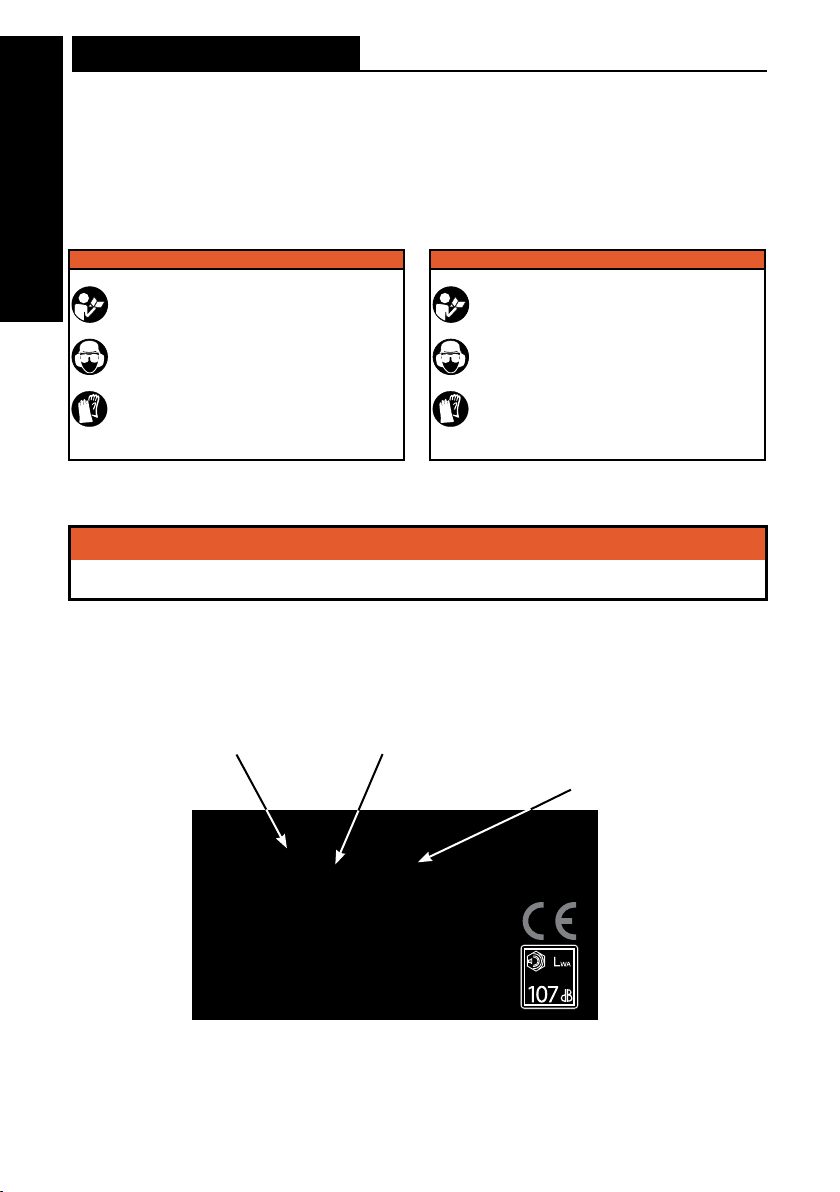
LABELS ON YOUR POWER CUTTER
SAFETY LABELS
ENGLISH
8 GPM POWER CUTTER 12 GPM POWER CUTTER
� WARNING
• Do not ex ceed 8 GPM (30 L PM) hydrau lic flow
or 2500 p si (172. 5 bar) hydr aulic pres sure
• Do NOT in sert too l into slot na rrower th an chain .
• Do NOT ru n the powe r cutter ba ckward s. The
chai n should t ravel away f rom the ope rator on
the to p of the bar an d return on t he bottom o f
the ba r.
• Do NOT op erate tool w ithout s olid footi ng and
fir m hand gri p.
• Fail ure to obser ve these p recauti ons can res ult
in ser ious inj ury. Flui ds escapi ng under
pres sure can pe netrate t he skin.
• Do not ex ceed 12 GPM (45 LPM) h ydrauli c flow
or 2500 p si (172. 5 bar) hydr aulic pres sure
• Do NOT in sert too l into slot na rrower th an chain .
• Do NOT ru n the powe r cutter ba ckward s. The
chai n should t ravel away f rom the ope rator on
the to p of the bar an d return on t he bottom o F
the ba r.
• Do NOT op erate tool w ithout s olid footi ng and
fir m hand gri p.
• Fail ure to obser ve these p recauti ons can res ult
in ser ious inj ury. Flui ds escapi ng under p ressure
can pe netrate t he skin.
� WARNING
� WARNING
• Do NOT op erate powe r cutter w ithout s ide cover.
• Do NOT op erate powe r cutter w ithout b affle drain.
• Do NOT us e this powe r cutter c over on any ot her power c utter mod el.
• Fail ure to obser ve these p recauti ons can res ult in ser ious inju ry.
NAMEPLATE LABEL
Model 890 F4
Serial# XXYYZZZZZ
Blount, Inc.
4909 SE International Way
Portland, OR 97222 USA
© 2018 ICS®, Blount International Inc. REV07192018 P/N 566594
8
YY = Month of Manufacture (ie. 07)XX = Year of Manufacture (ie. 15)
ZZZZ = Saw number within
production batch in sequential
order beginning with 00001
Page 9
890F4 OPERATOR MANUAL
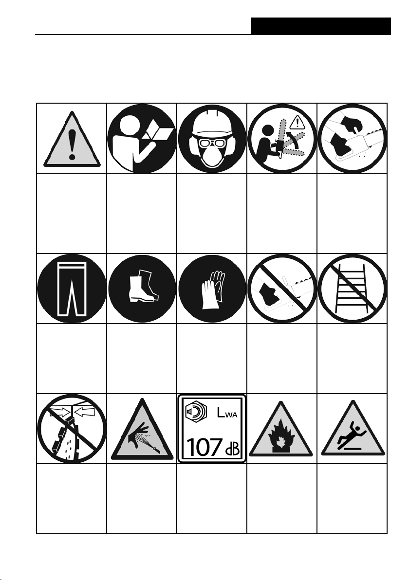
THE FOLLOWING SYMBOLS ARE FOUND THROUGHOUT THIS MANUAL
AND/OR ON THE POWER CUTTER AND ARE DESIGNED TO MAKE
YOU AWARE OF POTENTIAL HAZARDS OR UNSAFE PRACTICES.
Symbols & Labels
SYMBOLS AND LABELS
SAFETY ALERT
Indicates that the
text that
follows explains a
danger,
warning or caution.
WEAR LONG
PANTS
Wear long pants
when operating the
power cutter.
READ
INSTRUCTIONS
The original
instruction manual
contains important
safety and operating
information. Read
and follow the
instructions carefully.
WEAR FOOT
PROTECTION
Wear appropriate
closed-toe boots
when operating the
power cutter.
WEAR
PROTECTION
Wear eye , hearing
and respiratory
protection and a
protective helmet
when operating the
power cutter.
WEAR HAND
PROTECTION
Wear hand
protection when
operating the power
cutter.
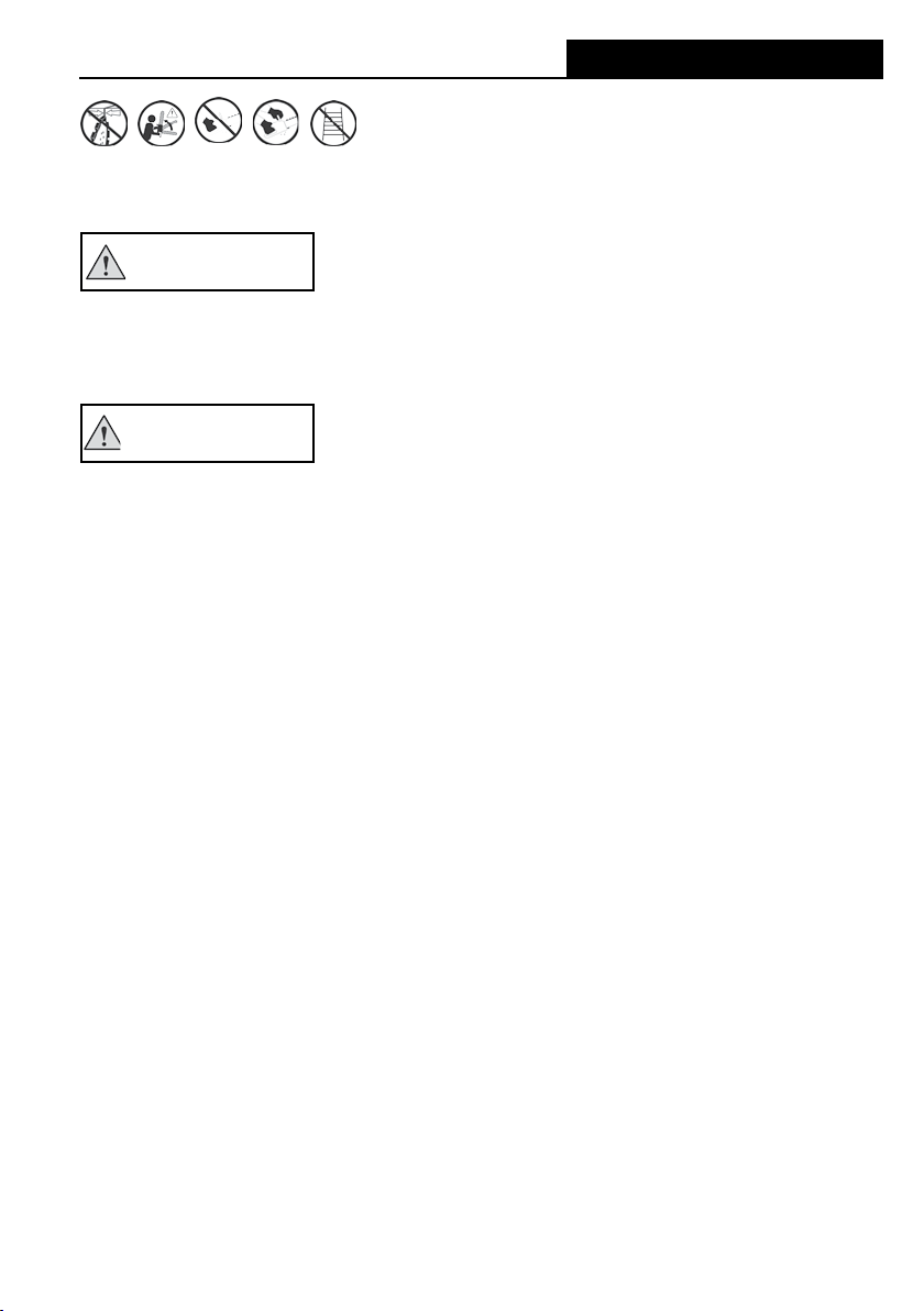
BEWARE OF
KICKBACK
Kickback can cause
severe injuries.
ONE-HANDED
HOLD
Do not operate the
power cutter with
only one hand.
TWO-HANDED
HOLD
Operate the power
cutter with two
hands, securely
gripping both
handles
DO NOT USE A
LADDER
Never stand on a
ladder when using
the power cutter.
KERF WIDTH
Do not insert tool
into slot
narrower than chain.
© 2018 ICS®, Blount International Inc. REV07192018 P/N 566594
FLUIDS UNDER
PRESSURE
Fluids escaping
under pressure
can penetrate skin
and cause severe
personal injury.
SOUND POWER
Sound power level
is 107 dB(A).
FIRE DANGER
Risk of re if
warnings not
followed.
SLIPPERY
SURFACE
Unsure footing can
lead to
accidents.
9
Page 10

Names & Terms
ICS 890F4 NAMES AND TERMS
Bae Drain
A device for controlling slurry and cutting debris in the side cover to
ENGLISH
reduce chain stretch and protect the operator from other projectiles.
Bar retaining plate
The plate between the guidebar and side cover that clamps the guidebar
to prevent movement during operation.
Bar slot
The slot feature on the guidebar that ts over the bar studs.
Bystander safety zone
A 6 m (20 ft) circle around the operator that must remain free from
bystanders, children and pets.
Chain catcher
A device for retaining the chain if it breaks or derails.
Chain pitch
The distance between any three consecutive rivets on the chain divided
by two.
Chain tensioning screw
An adjustment screw used to set proper tension on the chain and
compensate for chain stretch from normal use.
Front handle
The support handle located at or toward the front of the power cutter
intended to be gripped by the left hand.
Guidebar
A railed structure that supports and guides the chain. Sometimes simply
called the “bar”.
Kickback
The rapid backward and/or upward motion of the guidebar, occurring when
the chain near the top area of the nose of the guidebar contacts a foreign
object or snags in the workpiece.
Mud ap
A barrier to deect slurry, cutting debris and other projectiles from
operator.
890F4 OPERATOR MANUAL
10
© 2018 ICS®, Blount International Inc. REV07192018 P/N 566594
Page 11

890F4 OPERATOR MANUAL
Names & Terms
ICS890 NAMES AND TERMS
Powerhead
A power cutter without the chain or guidebar.
Pushback
The rapid backward motion of the guidebar, occurring when the chain on
the top straight portion of the guidebar contacts a foreign object or
snags in the workpiece.
Rear handle
The support handle located at or toward the rear of the power cutter
intended to be gripped by the right hand.
Rear hand guard:
A structural barrier at the bottom of the rear handle to protect the operator in
case the chain breaks or derails. Does not meet ISO 14982 Requirements.
Side cover:
The component on the powerhead that covers the drive sprocket and directs
debris away from the operator during use.
Side cover nuts:
The components on the side cover that secure the side cover, bar
retaining plate and guidebar.
Trigger lock-out
A device that prevents the unintentional operation of the throttle trigger until
manually released.
Trigger
A mechanism that controls motor operation.
WallWalker®
A device used as a fulcrum to provide mechanical advantage during
cutting.
Water shut-o valve
A mechanism that controls water delivery and ow to the guidebar and chain.
© 2018 ICS®, Blount International Inc. REV07192018 P/N 566594
11
Page 12

Product Identication
PRODUCT IDENTIFICATION
ENGLISH
Trigger lock-out
Trigger
Rear hand guard
Baffle drain
890F4 OPERATOR MANUAL
Bar slot
Bar studs
Bar retaining plate
WallWalker®
Side
cover
Side cover
nuts
Mud flap
Chain catcher
Guidebar
Chain tensioning screw
© 2018 ICS®, Blount International Inc. REV07192018 P/N 566594
12
Powerhead
Front handle
Rear handle
Water shut
off valve
Page 13

890F4 OPERATOR MANUAL
Hydraulic Supply
Quick-Disconnect
Hydraulic Return
Quick-Disconnect
Water hose
Product Identication
Direction of hydraulic ow
© 2018 ICS®, Blount International Inc. REV07192018 P/N 566594
13
Page 14

Unpacking & Assembly
890F4 OPERATOR MANUAL
BOX CONTENTS
ENGLISH
Minimum contents for all packages shown. Some packages also contain
guidebar and diamond chain.
See Z 34 for a list of compatible guidebars and diamond chain.
GUIDEBAR AND DIAMOND CHAIN
INSTALLATION & TENSIONING
Following are the basic instructions for guidebar and diamond chain
installation and tensioning.
WARNING
Never perform any maintenance or adjustments on the power cutter while
the hydraulic power source is connected.
Improper chain tension can lead to failure of the chain or derailing of the
chain o of the guidebar.
Check tension frequently and adjust if drive links of chain hang 18 mm (3/4 in)
or more below the guidebar groove
CAUTION
Always wear gloves when handling the bar and chain.
These components can develop sharp edges and cause cuts.
© 2018 ICS®, Blount International Inc. REV07192018 P/N 566594
14
Page 15

890F4 OPERATOR MANUAL
STEP 1
Disconnect hydraulic power supply.
STEP 2
Loosen the side cover nuts and
remove the side cover and bar
retaining plate.
Unpacking & Assembly
GUIDEBAR AND DIAMOND CHAIN
INSTALLATION & TENSIONING
STEP 3
Turn the chain-tensioning screw
counterclockwise until the pin
comes to a stop.
© 2018 ICS®, Blount International Inc. REV07192018 P/N 566594
15
Page 16

Unpacking & Assembly
GUIDEBAR AND DIAMOND CHAIN
INSTALLATION & TENSIONING
ENGLISH
STEP 4
Place the bar onto the studs
without engaging tensioner pin.
Assure bar is in contact with the
drive sprocket.
890F4 OPERATOR MANUAL
16
STEP 5
Install the chain around the drive
sprocket and then around the nose
sprocket before inserting into the
bar groove.
© 2018 ICS®, Blount International Inc. REV07192018 P/N 566594
Page 17

890F4 OPERATOR MANUAL
STEP 6
Engage the tensioner pin into the
bar. Make sure all of the drive links
are inside the top and bottom bar
grooves, then pre-tension the
chain.
Unpacking & Assembly
GUIDEBAR AND DIAMOND CHAIN
INSTALLATION & TENSIONING
FRONT
STEP 8
Install the side cover over the
bar studs and finger tighten side
cover nuts.
© 2018 ICS®, Blount International Inc. REV07192018 P/N 566594
STEP 7
Install the bar retaining plate over
the bar studs. Assure plate is
properly oriented so "FRONT" is
facing outward (as shown).
17
Page 18

Unpacking & Assembly
GUIDEBAR AND DIAMOND CHAIN
INSTALLATION & TENSIONING
ENGLISH
chain tensioner
STEP 9
Lift up on the nose of the bar and
tension the chain. Do not over
tension the diamond chain. Loss of
power will result.
890F4 OPERATOR MANUAL
18
CORRECT CHAIN TENSION
STEP 9
Continue to lift up on the nose
of the bar and firmly tighten the
side cover nuts using the scrench
(approximately 20 -25 ft. lbs (27-33
Nm). Improper torque can cause the
bar to slip.
© 2018 ICS®, Blount International Inc. REV07192018 P/N 566594
CHAIN TOO TIGHT CHAIN TOO LOOSE
Page 19

890F4 OPERATOR MANUAL
Unpacking & Assembly
CHECKING & ADJUSTING CHAIN TENSION
All chains have a tendency to stretch when used. Diamond chains stretch
more than wood cutting chains because of the abrasive materials they
are cutting.
WARNING
Improper chain tension can lead to breakage of the chain or derailing of the
chain o of the guidebar.
Check chain tension frequently and adjust if drive links of chain hang 18 mm
(3/4 in) or more below the guidebar.
IMPORTANT
When a chain stretches to a point where the drive links are hanging
approximately 12 mm (1/2 in) to 18 mm (3/4 in) below the guidebar groove, it is
time to tension the chain.
A tight chain may rob power reducing cutting performance and increasing
chain friction, resulting in chain stretch. If the tension is set too loose the chain
could be thrown o of the bar or allow the sprocket to turn without turning the
chain which will damage the drive links.
CONNECTING TO HYDRAULIC SUPPLY
Assure hydraulic hoses are connected to power cutter with the proper ow
direction. The chain should travel away from the operator on the top of the bar
and return on the bottom of the bar. If hydraulic motor does not turn when
trigger is depressed, this may be an indication that the hydraulic ow direction
is likely reversed. Refer to diagram on page 13 for more details.
hydraulic ow direction
© 2018 ICS®, Blount International Inc. REV07192018 P/N 566594
19
Page 20

Unpacking & Assembly
890F4 OPERATOR MANUAL
CONNECT TO WATER SUPPLY
Following are the basic instructions for correct water supply to the
power cutter.
CAUTION
ENGLISH
Insucient water supply will result in excessive chain stretch and may
cause chain breakage, damage to the guidebar, nose sprocket and drive
sprocket.
Never operate the power cutter with insucient water supply. In all cases,
assure that the water supply is delivering 1.5 bar (20 psi) pressure to the power
cutter at a minimum ow rate of 4 lpm (1gpm).
Inadequate water can result in increased potential for harmful airborne
particulates.
ICS® power cutters require a continuous water supply to the guidebar and
chain for the key purposes of cooling, lubrication and dust suppression. The
potential for airborne particulates depends on many factors including, but not
limited to, the material being cut, application and cutting environment.
NOTE: Local and/or regional regulation can vary widely. It is the responsibility
of the operator to wear appropriate dust protection applicable in their area and
suitable to the application.
Attach to water supply capable of delivering 1.5 bar (20 psi) pressure
to the power cutter at a minimum flow rate of 2 gpm/8 lpm. The single
most important factor an operator can control to increase chain life is
to use adequate water pressure.
© 2018 ICS®, Blount International Inc. REV07192018 P/N 566594
20
Page 21

890F4 OPERATOR MANUAL
Operation
OPERATION
Following are the basic instructions for safe operation of the power cutter.
WARNING
Never start the power cutter without the bar, chain and side cover properly
assembled.
Unintentional contact with moving chain or components may occur.
DO NOT operate the power cutter with loose, missing, damaged or improperly
installed or repaired parts.
Check that the components shown below are intact, undamaged, and installed
correctly:
• Side cover nuts torqued down properly. Loose or improperly torqued side
cover nuts can lead to chain tensioner breakage
• Side cover not damaged and bae drain not plugged
• Handles not loose, gripping areas are clean and undamaged
• Mud ap is not ripped, torn or missing and is fully attached to the power cutter
• Guidebar not bent or otherwise damaged such as rails dished and uneven
• Nose sprocket not excessively worn or broken, and turns freely
• Diamond chain does not have loose rivets, chassis or drive link damage or
missing diamond segments
• Chain tensioner mechanism functions properly and pin is not bent or broken
• Drive sprocket not excessively worn
• Check alignment of drive sprocket and guidebar
• Assure proper chain tension: The chain should be easily pulled around the
guidebar by hand
• Assure all safety devices are properly mounted and functional and that all
controls are in proper working order
• Adequate water supply and pressure
Minimum flow: 2 gpm (8 lpm)
Minimum water pressure: 20 psi (1.5 bar)
• Proper hydraulic supply to the power cutter:
Maximum flow: 8 gpm (30 lpm) or 12 gpm (45 lpm), depending on power
cutter model
Maximum hydraulic pressure: 2,500 psi (172.5 bar)
© 2018 ICS®, Blount International Inc. REV07192018 P/N 566594
21
Page 22

Operation
890F4 OPERATOR MANUAL
PRE-OPERATION SAFETY CHECKS
• Assure proper chain tension: The chain should be easily pulled around
the guidebar by hand.
• Assure all safety devices are properly mounted and functional and that
ENGLISH
all controls are in proper working order.
• Be sure there are no obstructions (plumbing, electrical conduit, air
ducts, etc.) and no unnecessary people present
• Always wear protective clothing, including hard hat, eye protection,
hearing protection, non-slip safety boots, gloves. Avoid wearing loose
fitting clothing.
• Adequate water supply and pressure
Minimum flow: 2 gpm (8 lpm)
Minimum water pressure: 20 psi (1.5 bar)
• Proper hydraulic supply to the power cutter:
Maximum flow: 8 gpm (30 lpm) or 12 gpm (45 lpm),
depending on power cutter model
Maximum hydraulic pressure: 2,500 psi (172.5 bar)
IMPORTANT
The single most important factor an operator can control to increase chain
life is to use adequate water pressure. Insufficient water supply may result
in excessive wear to the chain, which can lead to loss of strength and chain
breakage, and/or damage to the guidebar nose sprocket.
© 2018 ICS®, Blount International Inc. REV07192018 P/N 566594
22
Page 23

890F4 OPERATOR MANUAL
Operation
PRECUT CHECKLIST
WARNING
Be sure that no part of the cutting system is contacting a solid object when
starting the power cutter.
The power cutter may react unexpectedly if the chain contacts a solid object.
WARNING
Sudden contact of the guidebar nose with a foreign object may generate
kickback.
Remove and/or avoid any obstructions (plumbing, water supply hoses,
electrical conduit, air ducts, etc.) that may interfere with the cut.
To avoid electrocution, check for live electrical wires.
Wires may be hidden within or behind walls and/or laying around the
workspace. Assure that any ancillary electrical equipment (fans, pumps,
vacuums, etc.) are properly grounded and certied for use in the intended
environment.
Always operate the power cutter with solid footing and both hands on the
power cutter.
Keep your left hand on the front handle and your right hand on the rear handle.
Wrap your thumbs around the handles to assure you maintain a secure grip on
both handles.
Always wear protective clothing.
At a minimum always wear eye protection and/or face shield, hearing
protection, long sleeve shirt, long pants, closed toe shoes with non-slip soles,
and gloves. In many work situations, a hard hat, steel toed shoes and a
respirator may also be required. Avoid loose tting clothing. Follow all local
regulations regarding PPE.
Cutting with the power cutter may generate sparks, especially when cut-
ting through metal (such as rebar), and may start a re in combustible
materials such as dry grass, wood and fuel.
Be sure to use adequate water pressure and have re ghting equipment
readily available.
© 2018 ICS®, Blount International Inc. REV07192018 P/N 566594
23
Page 24

Operation
890F4 OPERATOR MANUAL
CUTTING WITH THE POWER CUTTER
WARNING
DO NOT insert the guidebar into a slot narrower than the width of the chain.
ENGLISH
Rapid pushback, kickback and/or chain breakage could result.
Be sure cut concrete cannot fall and injure the operator or bystanders.
Assure cut piece is controlled and does not fall unexpectedly.
NOTE: Concrete is very heavy; one cubic foot = 30 cm x 30 cm x 30 cm = 68 kg
(12 in x 12 in x 12 in = 150 lbs).
CAUTION
Slippery or unstable surfaces such as ladders may cause a loss of balance
or control of the power cutter.
Always keep proper footing and operate the power cutter only when standing
on xed, secure and level surface.
Unexpected loss of control of the power cutter and loss of balance can
result in injury.
Do not overreach and do not cut above shoulder height.
Do not allow workpiece to pinch the guidebar and chain, or rapid pushback
could result.
Always cut bottom of opening rst and assure workpiece is secure and does
not shift during cutting operations.
Do not operate power cutter upside down.
Cutting debris can be directed back towards the operator.
Take special precautions when cutting in horizontal orientation.
Be aware that debris may be ejected dierently than when cutting in a vertical
position.
IMPORTANT
Always operate power cutter at full throttle.
For best results, always operate the power cutter at full power.
© 2018 ICS®, Blount International Inc. REV07192018 P/N 566594
24
Page 25

890F4 OPERATOR MANUAL
Operation
CUTTING WITH THE POWER CUTTER
To assure the best performance from your ICS power cutter, follow all safety
precautions and recommended techniques. Additional helpful information can be
obtained at icsdiamondtools.com.
CONCRETE/MASONRY CUTTING
Planning the Cut
1. Select the proper chain type for the material being cut. Refer to the chain
selection guide in this manual (page 32).
2. Outline the cut with a permanent marker for a visual cutting guide.
WARNING
3. Avoid pinching the guidebar and chain by using shims or
other anchoring devices to stabilize the workpiece. Always
plan to cut the bottom of an opening rst, then
top or sides. Save the easiest cut for last. (see
image at right)
4. Be sure cut concrete cannot fall and injure the operator
or bystanders. As the cut is being completed, assure that
appropriate bracing is in place to control the cut section
of the workpiece. Concrete is very heavy,
one cubic foot = 30 cm x 30 cm x 30 cm = 68 kg (12 in x 12 in x 12 in = 150 lbs)
3
22
1
© 2018 ICS®, Blount International Inc. REV07192018 P/N 566594
25
Page 26

Operation
890F4 OPERATOR MANUAL
CONCRETE/MASONRY CUTTING
Recommended Concrete Cutting Techniques
ENGLISH
1. Plunge in
2. Cut down to open slot
3. Insert WallWalker® rotate rear handle up,
to rotate the nose down
4. Rotate rear handle down, to rotate the
nose up.
5. Reengage WallWalker® and repeat Steps
3 and 4
© 2018 ICS®, Blount International Inc. REV07192018 P/N 566594
26
Page 27

890F4 OPERATOR MANUAL
Operation
CUTTING TIPS
• For the straightest cuts use the “Step Cut” method:
• First score the entire cut line approximately a half-inch deep using
the nose of the guidebar.
• Next, deepen the cut by about two inches
• Then plunge all the way through and complete the cut using the
WallWalker® as a pivot point and pull on the rear handle to rotate
the bar into the cut.
• When the WallWalker is extended in the mechanical mode, the Wall Walker
provides a 4:1 mechanical advantage.
• Always operate the concrete power cutter at full throttle. If too much force
is applied, the power cutter will lug or stall. The chain will not have enough
speed to cut eectively. If too little feed force is applied, the diamonds will
skid and glaze over.
• Plunge cut instead of starting at the top surface of the wall. This will
reduce chatter, extend diamond life, create a straighter cut and more
quickly enable the use of the WallWalker.
• When cutting heavy rebar, slowly “rock” the power cutter so that you’re
always cutting concrete as well as steel. This will help keep the diamonds
exposed. Also, expect less chain life when cutting heavy rebar.
• Expect more chain stretch when making nose-buried cuts for extende
periods of time, as the chain does not have a chance to “throw” the slurry
away from the nose of the guidebar (use step cut method).
• If the power cutter begins to cut consistently crooked, stop the power
cutter, remove the bar and chain and turn the bar over and use the other
side. Dress worn rails with a belt sander, at le or bar rail dresser.
Note: The normal life of a guidebar is two to three diamond chains (with
rotation after every chain). Heavy rebar can shorten guidebar life.
• The guidebar is solely a guide track for the chain. Never use the guidebar
to lift, twist or pry concrete material.
• When using a new chain, you can increase the initial cutting speed by
“opening up the diamonds”. This can be accomplished by rst making a
few cuts in an abrasive material such as a cinder block or brick.
© 2018 ICS®, Blount International Inc. REV07192018 P/N 566594
27
Page 28

Operation
890F4 OPERATOR MANUAL
PIPE CUTTING USING
POWERGRIT® UTILITY CHAIN
To assure the best performance from your ICS® power cutter when cutting
ductile iron pipe or similar pipe materials, follow all safety precautions and recommended cutting techniques.
ENGLISH
WARNING
Never attempt to cut ductile iron pipe or similar pipe materials with the
power cutter unless using PowerGrit® Utility Chain.
Using concrete diamond chain in these applications can cause the chain to
snag abruptly in the cut which may result in chain breakage, pushback and/or
kickback.
Always assure that pipe is properly evacuated before cutting.
Pipes may contain sewage, gas or other hazardous materials.
Always support the pipe on both sides of the cut to assure the cut remains
open throughout the cutting operation, including when the cut is nished.
An improperly supported pipe can cause the cut to close, pinching the chain
and guidebar which may result in chain breakage, pushback and/or kickback.
Recommended Pipe Cutting Techniques
1. Make a small plunge cut into the lower quadrant
of the pipe to relieve internal pressure and allow
contents to drain from pipe in a controlled manner.
2. With pipe drained, cut from the top of pipe and
continue through bottom of the pipe.
3. To assure straightness of cut, guidebar should
extend completely through the pipe during the cut.
4. To assist with cutting, engage the WallWalker®
in the cut when possible to provide additional
leverage and alternate cutting between the near
and far side walls of the pipe.
© 2018 ICS®, Blount International Inc. REV07192018 P/N 566594
28
Page 29

890F4 OPERATOR MANUAL
Maintenance
MAINTENANCE
IMPORTANT
SYSTEM CLEAN-UP
• After cutting, run the power cutter for at least 15 seconds with the water on
to flush slurry and debris from diamond chain, guidebar and drive sprocket.
• Wash concrete slurry and debris from power cutter assembly.
• Remove guidebar and chain. Flush out the chain tensioner and side cover
with water. Lubricate tensioner with waterproof grease.
• After cleaning the power cutter, spray the entire power cutter body, chain,
guidebar, and drive sprocket with lightweight oil. Using lightweight oil on
the power cutter will minimize rust and help reduce slurry build up.
AFTER EACH USE
• Inspect drive sprocket for wear
• Inspect and tighten all fasteners as necessary.
• Flush and rinse the power cutter, guidebar and chain with water
• Check trigger function assembly
• Check mud ap for tears or damage
• Check guidebar and chain for damage or missing segments
• Check trigger cover bubble levels
• With power cutter disconnected from power source, check hose whips
for leaks or damage.
• Inspect drive sprocket for wear.
• Replace when the drive teeth are worn more than half way through.
© 2018 ICS®, Blount International Inc. REV07192018 P/N 566594
29
Page 30

Maintenance
890F4 OPERATOR MANUAL
DRIVE SPROCKET
Drive teeth
• The drive sprocket is a wear item and
should be replaced every two to three
chains, or when the teeth become pointed
ENGLISH
or if a groove cuts through top of tooth.
• Inspect the sprocket for wear.
• Inspect drive shaft for wear.
Snap Ring
DRIVE SPROCKET ASSEMBLY
REMOVAL/INSTALLATION
• Disconnect power cutter from the
power source
• Remove the side cover, bar retainer plate,
guidebar and diamond chain
• Remove snap ring from shaft
• Slide drive sprocket off shaft
• Slide new sprocket onto shaft
• Replace snap ring onto shaft and assure complete engagement
in shaft groove
• Installation of new drive sprocket is complete.
• Reinstall guidebar, diamond chain, bar retainer plate and side cover.
• Assure diamond chain and guidebar are in good, useable condition. Worn
or damaged guidebar and chain can damage the new drive sprocket.
Drive Sprocket
30
Snap Ring
© 2018 ICS®, Blount International Inc. REV07192018 P/N 566594
Drive Shaft
Drive Sprocket
Page 31

890F4 OPERATOR MANUAL
Maintenance
CHAINS & GUIDEBARS
IMPORTANT
Inspect chain segments and drive links for damage or excessive wear. Chains
with damage or excessive wear should not be used or repaired, they should be
replaced.
NOTE: Guidebars are designed to be used on both sides. If the cut is consistently
leading to one side, turn the guidebar over. It is recommended to turn the guidebar
over with every new chain.
• A table mounted belt, disc sander, at le or bar rail dressercan be used to
square the rails of a worn guidebar. A badly worn guidebar can quickly damage
the chain. If the chain is touching the bottom of the guidebar groove, replace
the guidebar.
• Check the guidebar for straightness.
• Proper chain tension will extend guidebar life.
• Under some circumstances, especially low water pressure, the sprocket nose
can wear out before the guidebar body. Sprocket nose assemblies may be
replaced by an Authorized Service Center.
• Periodically clean the water ports inside the groove of the guidebar using a
small diameter piece of wire or pipe cleaner.
• The guidebar is solely a guide track for the chain. Never use the guidebar to lift,
twist or pry concrete material.
• Prior to storage, spray the chain and guidebar with lightweight oil.
CHAIN TENSIONER
The chain tensioner can become clogged with concrete slurry during cutting.
• After each use thoroughly ush the chain tensioner with water and apply a
liberal amount of waterproof grease covering the chain tensioner screw.
Chain Tensioner
FRONT
© 2018 ICS®, Blount International Inc. REV07192018 P/N 566594
31
Page 32

Maintenance
890F4 OPERATOR MANUAL
890F4 CHAIN SELECTION GUIDE & CONSUMABLES
890 F4 Chain Selection Guide
Medium
Concrete/Light
Reinforcement
◊ ◊
ENGLISH
FORCE4®
General Purpose
FORCE4® Premium L
Longer Cutting Life
FORCE4® Premium S
Faster Cutting Speed
FORCE4®
Ideal for brick & block
PowerGrit
For Utility Pipe
Chain &
Applications
Abrasive
®
Soft Stone/
Abrasive/Brick
◊
Natural Stone
◊ ◊ ◊
◊ ◊ ◊
890F4 Consumables
10 in (25 cm) 15 in (38 cm) 20 in (50 cm) 25 in (63 cm)
FORCE4® Diamond Chain p/n 531743 p/n 525342 p/n 531749 p/n 525345
Premium L Diamond Chain p/n 531745 p/n 525343 p/n 531751 p/n 525346
FORCE4®
FORCE4® Premium S Diamond Chain p/n 531739 p/n531735 p/n 531741 p/n 531737
FORCE4® Abrasive Diamond Chain p/n 531747 p/n 525344 p/n 531753 p/n 525347
®
Diamond Chain p/n 537764 p/n 537765 p/n 545017
PowerGrit
FORCE4® Guidebar p/n 529829 p/n 523080 p/n 529767 p/n 525320
Drive Sprocket 565065
Hard
Concrete/ Heavy
Reinforcement
Ductile Iron/Cast
Iron/PVC/HDPE
◊
32
© 2018 ICS®, Blount International Inc. REV07192018 P/N 566594
Page 33

890F4 OPERATOR MANUAL
TROUBLESHOOTING
PROBLEM Possible Cause
Low hydraulic oil.
POWER CUTTER WON'T REACH
FULL RPM
SLOW CHAIN SPEED
POOR CUTTING SPEED
PREMATURE CHAIN STRETCH
Worn hydraulic power cutter motor
Worn hydraulic val ve assembly.
Worn powerpack pump
All of the above, plus chain tension too tight. Chain should al ways be
able to be pulled around the guidebar by hand. It i s norm al for the drive
links of the chain to hang below the guidebar. See pages 15-19 for chain
tensioning instructions.
All of the above, plus d iamonds may be glazed over. Make a few cuts in an
abrasive material to expose the diamonds.
Chain or diamonds m ay be worn out.
Worn dr ive sprocket.
Init ial chain tension too tight.
Bar nose buried in cu t.
Not enough water pressure. The minimum water pressure required is 1.5
bar (20 psi).
Chain comes i n contact with ground, dirt, g ravel a nd/or sand.
Troubleshooting
CHAIN TENSIONER BREAK AGE
WATER NOT FLOWING
MOTOR DOES NOT TURN
CHAIN BREAKAGE
© 2018 ICS®, Blount International Inc. REV07192018 P/N 566594
Side cover nuts are not tight e nough. Torque to 27-33 Nm (20 -25 ft-lbs).
Tensioning with side cover nu ts already tight.
Tensioner pin not aligned and side cover tightened.
Water hose is kinked or water supply not turned on.
Water ports plugged with debris.
Damaged or worn water valve in power cutter.
Hydraulic lines connected backwards or power pack is set to reverse.
Chain tension is too tight.
Improper chain tension.
Insufficient water pressure.
Inserting power cutter into slot nar rower t han di amond chain segments.
Using chain that is a lready stretched beyond abilit y to tension .
Contact with exposed rebar or steel.
33
Page 34

Technical Speccations
TECHNICAL SPECIFICATIONS
890 Series 8 gpm (30 lpm) 890 Series 12 gpm (45 lpm)
890F4 OPERATOR MANUAL
Weight w/out bar and
ENGLISH
chain (1' hose whips)
Length 23 inches (58.5 cm)
Height 10.5 inches (26.5 cm)
Width 9.5 inches (24 cm)
Hydraulic Supply
Hydraulic Fluid
Requirements (Type)
Water Pressure Minimum: 20 psi (1.4 bar)
Water Flow 2 gpm (8 lpm) minimum
Operating Speed
Torque(1) 7.0 ft-lbs (9.6 Nm) 10.0 ft-lbs (13.5 Nm)
Horsepower (1) 6 hp (4.5 kW) 8 hp (6.0 kW)
Guaranteed Sound Power
Level Lwa (2)
Equivalent Sound Pressure
at the Operator's E ar L
Vibration a
Vibration a
(1)Measured using 18HP hydraulic power pack (8 gpm/30 lpm and 23HP hydraulic power pack (12 gpm/45 lpm) at 2000psi/138 bar.
(2) Measured in accordance with ISO3744:2010
(3) Measured in accordance with ISO5349-1:2001
hv, eq
Cutting (3)
hv, eq
Cutting (3)
pA
Concrete
PowerGrit
(2)
8 gpm (30 lpm) @
2,500 psi (172.5 bar)
6,100 rpm (avg. free running)
5,500 sfm (avg. free running chain)
23.5 lbs (10.6 kg)
PC HYDREX MV32 or equi valent
107 dB(A) (K=0.2 dB(A ))
98 dB(A) (K=0.7 dB(A ))
2.0 m/s2 (K=0.1 m/s2) Front Handle
6.0 m/s2 (K=1.4 m/s2) Rear Handle
4.6 m/s2 (K=0.1 m/s2) Front Handle
4.8 m/s2 (K=0.3 m/s2) Rear Handle
12 gpm (45 lpm) @
2,500 psi (172.5 bar)
6,500 rpm (avg. free r unning)
5,80 0 sfm (avg. free running chain)
34
© 2018 ICS®, Blount International Inc. REV07192018 P/N 566594
Page 35

890F4 OPERATOR MANUAL
Service Centers
AUTHORIZED SERVICE CENTERS
KENNEDY EQUIPMENT CO INC 714.771.7324 748 N. LEMON ST ORANGE CA 92867
ABLE TOOL EQUIPMENT 860.289.2020 410 BURNHAM STREET SOUTH WINDSOR CT 06074
EQUIPSERV LLC 770.709.5101 6225 MABELTON PARKWAY SW MABLETON GA 30126
STAR EQUIPMENT 515.283.2215 1401 2nd AVE DES MOINES IA 50314
MCCANN INDUSTRIES, INC. 630.627.8700 543 SOUTH ROHLWING RD ADDISON IL 60101
CLEAN RITE TECH 504.468.7997 1332 FULTON ST KENNER LA 70062
ACE CUTTING EQUIPMENT 248.449.4944 25806 NOVI RD. NOVI MI 48375
CONCRETE CUTTING & CORING 952.882.0980 12690 CREEK VIEW AVE SAVAGE MN 55378
ACME ELECTRIC 218.628.3523 4332 GRAND AVE DULUTH MN 55807
MERLIN STELZER SALES CO., INC. 314.535.7540 4109 PAPIN ST ST. LOUIS MO 63110
ACME ELECTRIC 701.258.1267 3840 E. ROSSER AVE BISMARCK ND 58501
ACME ELECTRIC 701.746.6481 1705 12TH AVE NORTH GRAND FORKS ND 58203
ACME ELECTRIC 701.476.4600 920 36TH STREET S.W. FARGO ND 58103
ACME ELECTRIC 701.839.2263 700 20TH AVE S.E. MINOT ND 58701
ADMAR SUPPLY 585.272.9390 1950 BRIGHTON-HENRIETTA TL RD ROCHESTER NY 14623
ADMAR SUPPLY 315.433.5000 6014 DROTT DR EAST SYRACUSE NY 13057
ADMAR SUPPLY 518.690.0750 878 ALBANY SHAKER RD LATHAM NY 12110
ADMAR SUPPLY 607.754.4700 2305 OLD VESTAL RD VESTAL NY 13850
ADMAR SUPPLY 716.873.8000 1394 MILITARY RD BUFFALO NY 14217
CESSCO, INC. 503.288.1242 4222 N.E. COLUMBIA BLVD. PORTLAND OR 97218
TRI-BORO CONST. SUPPLIES 800.632.9018 435 LOCUST ST DALLASTOWN PA 17313
LEHIGH CONSTRUCTION SUPPLY CO. 570.654.3981 295 SCHOOLEY AVE EXETER PA 18643
DRIVEKORE, INC. 717.766.7636 101 WESLEY DRIVE MECHANICSBURG PA 17055
ECKHART CONSTRUCTION 803.802.6635 1019 SOCIETY LANE FORT MILL SC 29707
STAN HOUSTON EQUIPMENT 605.336.3727 501 SOUTH MARION ROAD SIOUX FALLS SD 57106
STAN HOUSTON EQUIPMENT 605.348.1155 1210 DEADWOOD AVENUE RAPID CITY SD 57702
LINCOLN CONTRACTORS SUPPLY 414.541.1327 11111 WEST HAYES AVE MILWAUKEE WI 53227
LINCOLN CONTRACTORS SUPPLY 608.249.6476 901 WALSH RD MADISON WI 53714
LINCOLN CONTRACTORS SUPPLY 715.359.6111 5207 WESTFAIR AVE SCHOFIELD WI 54476
LINCOLN CONTRACTORS SUPPLY 920.757.1901 5663 NUEBERT RD APPLETON WI 54913
LINCOLN CONTRACTORS SUPPLY 920.432.8697 1654 MORROW ST GREEN BAY WI 54302
LINCOLN CONTRACTORS SUPPLY 715.874.4100 7840 PARTRIDGE AVE EAU CLAIRE WI 54703
LEE JENSEN SALES CO, INC 815 459-0929 101 WEST TERRA COTTA CRYSTAL LAKE IL 60014
ROCK-CRETE EQUIPMENT LTD. 604 464-1448 50 BURBIDGE STREET COQUITLAM BC V3K 6B1
CONCUT DIAMOND PRODUCTS 561-989-8895 6500 W ROGERS CIRCLE SUITE 6000 BOCA RATON FL 33487
AUSTECH SUPPLIES PTY LTD 61298541200 UNIT 12, 197 POWER STREET GLENDENNING NSW 2761
HATCH BUILDING SUPPLY COMPANY 608 222-0011 5601 MANUFACTURERS DRIVE MADISON WI 53704
AMERICAN TOOL AND FASTENER 972-801-9909 1331 E PLANO PKWY STE #B PLANO TX 75074
HENARD UTILITY PRODUCTS, INC 501 268-1987 1920 S. MAIN STREET SEARCY AR 72143
DEALER PHONE ADDRESS CITY STAT E POSTAL CODE
© 2018 ICS®, Blount International Inc. REV07192018 P/N 566594
35
Page 36

890F4 OPERATOR MANUAL
ICS, Blount, Inc.
4909 SE International Way
Portland, OR 97222, USA
Tel 800.321.1240 Fax 503.653.4393
ICS, Blount Europe S.A.
Rue Emile Francqui, 5
1435 Mont-Saint-Guibert, Belgium
Tel +32 10 301 251 Fax +32 10 301 259
icsdiamondtools.com
© 2018 ICS®, Blount International Inc. REV07192018 P/N 566594
 Loading...