

Page 1

695XL
OPERATOR MANUAL
WARNING: READ AND UNDERSTAND ALL SAFETY WARNINGS
AND ALL INSTRUCTIONS BEFORE YOU USE THIS EQUIPMENT.
Failure to follow the warnings and instructions may result in re, serious injury, or death.
SAVE ALL WARNINGS AND INSTRUCTIONS FOR FUTURE REFERENCE
© 2016 ICS®, Blount International Inc. Specications are subject to
change without notice. REV030816 F/N 577452
Page 2

695XL OPERATOR MANUAL 695XL OPERATOR MANUAL
This instruction manual contains translations of a manual drafted in English and
are provided to assist those who do not speak English as their rst language.
Being a technical writing, some terms may not have a like or equivalent meaning
as translated. Therefore, you should not rely on this translation, and should
cross-reference the English version, where relying on the translated instructions
could result in harm to your person or property.
© 2016 ICS®, Blount International Inc. Specications are subject to change
2 3
without notice. REV030816 F/N 577452
Page 3

TABLE OF CONTENTS
Table of Contents
SYMBOLS AND LABELS
ICS695XL NAMES AND TERMS
PRODUCT IDENTIFICATION
INTRODUCTION
SAFETY RULES
UNPACKING AND ASSEMBLY
FUELING
OPERATION
TRANSPORTING & STORING
MAINTENANCE
TROUBLESHOOTING
EMISSIONS
TECHNICAL SPECIFICATIONS
SERVICE CENTERS
4
8
10
11
12
16
23
26
36
37
45
47
49
50
© 2016 ICS®, Blount International Inc. Specications are subject to change
without notice. REV030816 F/N 577452
Page 4

Symbols & Labels
695XL OPERATOR MANUAL 695XL OPERATOR MANUAL
SYMBOLS AND LABELS
THE FOLLOWING SYMBOLS ARE FOUND THROUGHOUT THIS MANUAL
AND/OR ON THE SAW AND ARE DESIGNED TO MAKE YOU AWARE OF POTENTIAL
HAZARDS OR UNSAFE PRACTICES.
SAFETY ALERT
Indicates that the text that
follows explains a danger,
warning or caution.
WEAR LONG PANTS
Wear long pants when operating
the saw.
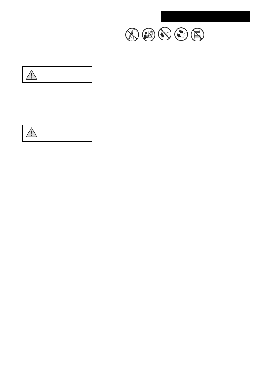
READ INSTRUCTIONS
The original instruction manual
contains important safety and
operating information. Read and
follow the instructions carefully.
WEAR FOOT PROTECTION
Wear appropriate closed-toe
boots when operating the saw.
WEAR EYE, HEARING AND
RESPIRATORY PROTECTION
WEAR HEAD PROTECTION
Wear eye , hearing
and respiratory protection and a
protective helmet when
operating the saw.
WEAR HAND PROTECTION
Wear hand protection when
operating the saw.
KERF WIDTH
Do not insert tool into slot
narrower than chain.
© 2016 ICS®, Blount International Inc. Specications are subject to change
4 5
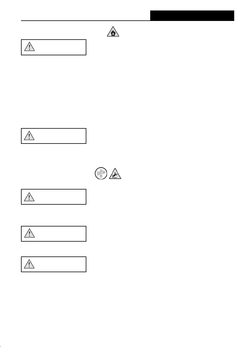
VENTILLATION REQUIRED
Use tool in a well ventillated area
without notice. REV030816 F/N 577452
Page 5
Symbols & Labels
SYMBOLS AND LABELS
THE FOLLOWING SYMBOLS ARE FOUND THROUGHOUT THIS MANUAL
AND/OR ON THE SAW AND ARE DESIGNED TO MAKE YOU AWARE OF POTENTIAL
HAZARDS OR UNSAFE PRACTICES.
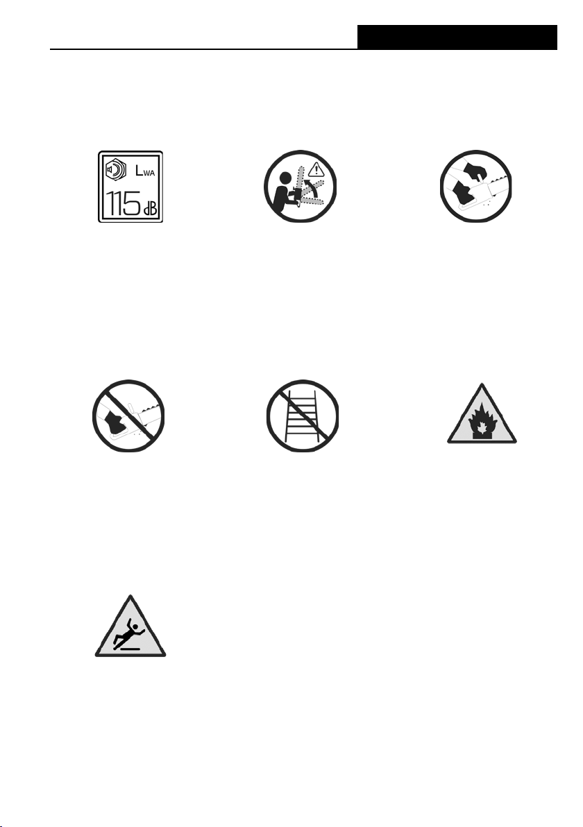
SOUND POWER
Sound power level is 115 dB(A).
ONE-HANDED HOLD
Do not operate the saw
with one hand.
BEWARE OF KICKBACK
Kickback can cause severe
injuries.
DO NOT USE A LADDER
Never stand on a ladder when
using the saw.
TWO-HANDED HOLD
Operate the saw with two hands,
securely gripping both handles
FIRE DANGER
Risk of re if warnings not
followed.
SLIPPERY SURFACE
Unsure footing can lead to
accidents.
© 2016 ICS®, Blount International Inc. Specications are subject to change
without notice. REV030816 F/N 577452
Page 6
Symbols & Labels
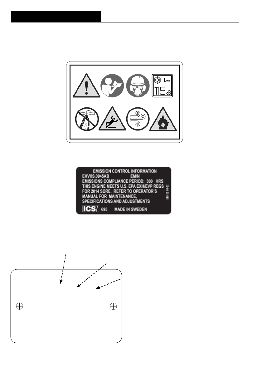
LABELS ON YOUR SAW
SAFETY LABEL
EMISSIONS LABEL
695XL OPERATOR MANUAL 695XL OPERATOR MANUAL
LABEL SHOWN FOR REFERENCE ONLY
NAMEPLATE LABEL
ÅÅÅÅ = Year of Manufacture (ie. 2015)
VV = Week number within the year (ie. 07)
ICS 695XL
s/n ÅÅÅÅ VVXXXXX
967 29 09-01
Blount, Inc.
Portland, OR, USA
e5*97/68SH3G3*
2010/26*0152*00 (II)
© 2016 ICS®, Blount International Inc. Specications are subject to change
6 7
without notice. REV030816 F/N 577452
XXXXX = Saw number within production
batch in sequential order beginning with
00001
Page 7
LABELS ON YOUR SAW
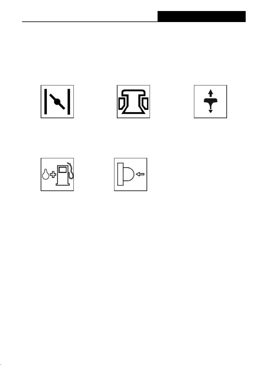
OPERATOR CONTROLS
Symbols & Labels
CHOKE CONTROL
MULTI-FUNCTION LEVER
REFUELING PRIMER/PURGER BULB
DECOMPRESSION VALVE STARTER HANDLE
© 2016 ICS®, Blount International Inc. Specications are subject to change
without notice. REV030816 F/N 577452
Page 8

Names & Terms
695XL OPERATOR MANUAL 695XL OPERATOR MANUAL
ICS695XL NAMES AND TERMS
Air box intake
The only entry point of air into the engine
Bar pad
The mounting pad on the powerhead that helps assure proper alignment of the
guidebar.
Bar slot
The slot feature on the guidebar that ts over the alignment block and bar stud.
Bystander safety zone
A 6 m (20 ft) circle around the operator that must remain free from bystanders,
children and pets.
Chain catcher
A device for retaining the chain if it breaks or derails.
Chain pitch
The distance between any three consecutive rivets on the chain divided by
two.
Chain tensioning screw
An adjustment screw used to set proper tension on the chain and compensate
for chain stretch from normal use.
Decompression valve
A device that relieves engine pressure to assist starting.
Front handle
The support handle located at or toward the front of the saw intended to be
gripped by the left hand.
Guidebar
A railed structure that supports and guides the chain. Sometimes simply called
the “bar”.
Kickback
The rapid backward and/or upward motion of the guidebar, occurring when the
chain near the top area of the nose of the guidebar contacts a foreign object or
snags in the workpiece.
Multi-function lever
A device for setting the choke and temporarily advancing the throttle in a
partially open position to aid starting.
Mud ap
A barrier to protect the operator from cutting debris and other projectiles.
© 2016 ICS®, Blount International Inc. Specications are subject to change
8 9
without notice. REV030816 F/N 577452
Page 9

Names & Terms
ICS695XL NAMES AND TERMS
On/O or “Stop” control
A control that allows the engine to run or causes the engine to stop.
Powerhead
A saw without the chain or guidebar.
Primer/Purger bulb
A device in the fuel system for supplying extra fuel or for evacuating air to aid
starting.
Pushback
The rapid backward motion of the guidebar, occurring when the chain on
the top straight portion of the guidebar contacts a foreign object or
snags in the workpiece.
Rear handle
The support handle located at or toward the rear of the saw intended to be
gripped by the right hand.
Rear hand guard:
A structural barrier at the bottom right side of the rear handle to protect the
operator in case the chain breaks or derails.
Side cover:
The component on the powerhead that covers the drive sprocket and directs
debris away from the operator during use.
Side cover nut:
The component on the side cover that secures the side cover and guidebar.
Throttle trigger lock-out
A device that prevents the unintentional operation of the throttle trigger until
manually released.
Throttle trigger
A mechanism that controls engine RPM.
WallWalker®
A device used as a fulcrum to provide mechanical advantage during cutting.
Water shut-o valve
A mechanism that controls water delivery and ow to the guidebar and chain.
© 2016 ICS®, Blount International Inc. Specications are subject to change
without notice. REV030816 F/N 577452
Page 10
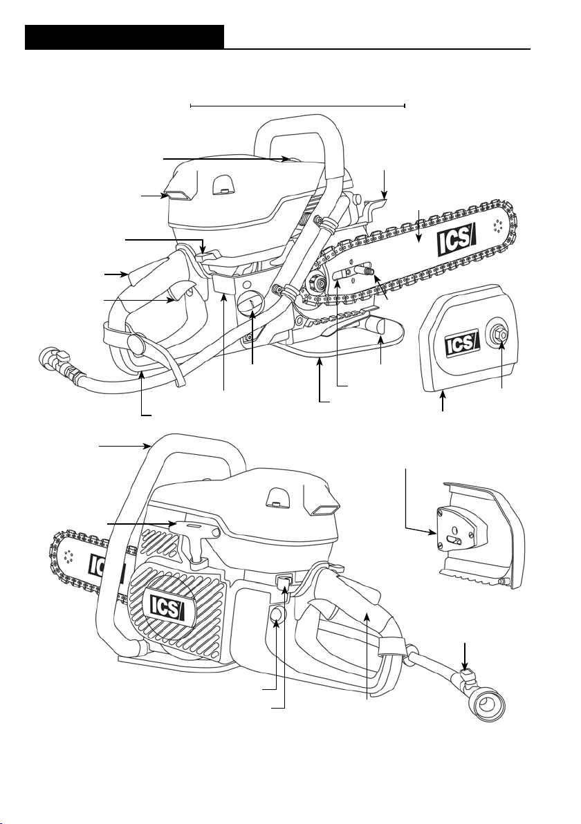
Product Identication
PRODUCT IDENTIFICATION
695XL OPERATOR MANUAL 695XL OPERATOR MANUAL
Powerhead
Decompression valve
Air box intake
Multi-function lever
Throttle trigger
lock-out
Throttle trigger
Front handle
Starter handle
Nameplate
Rear hand guard
Fuel filler cap
WallWalker®
Guidebar
Bar stud
Chain catcher
Bar slot
Mud flap
Side cover
Chain tensioning screw
Side cover nut
Water shut off valve
Primer/Purger
On/Off or Stop Control
© 2016 ICS®, Blount International Inc. Specications are subject to change
10 11
without notice. REV030816 F/N 577452
Rear handle
Page 11

Introduction
INTRODUCTION
The 695XL saw is designed to cut concrete, stone, and masonry when used with
the appropriate genuine ICS Diamond Chain. Ductile iron pipe may also be cut but
ONLY if using PowerGrit® Utility Saw Chain. This is a professional tool and
is solely intended for use by trained and experienced operators. A rst time
operator should obtain practical instruction before using the saw, as well as
reading and understanding this Operator’s Manual.
Local legislation and/or workplace standards may regulate the use of this saw.
Determine what regulations are applicable in the place you work before using
the saw.
Prop 65 statement:
California Proposition 65 (the Safe Drinking Water and Toxic Enforcement Act of
1986) refers to the California legislation that was intended by its authors to protect
California citizens and the State’s drinking water sources from chemicals known
to cause cancer, birth defects or other reproductive harm, and to inform citizens
about exposures to such chemicals. Proposition 65 requires businesses to notify
Californians about signicant amounts of chemicals in the products they purchase,
in their homes or workplaces, or that are released into the environment. By
providing this information, Proposition 65 enables Californians to make informed
decisions about protecting themselves from exposure to these chemicals.
Proposition 65 also prohibits California businesses from knowingly discharging
signicant amounts of listed chemicals into sources of drinking water.
The engine exhaust from this machine and some types of dust/debris created from
its normal operation may contain chemicals known to the State of California to
cause cancer, birth defects or other reproductive harm.
© 2016 ICS®, Blount International Inc. Specications are subject to change
without notice. REV030816 F/N 577452
Page 12

Safety Rules
695XL OPERATOR MANUAL 695XL OPERATOR MANUAL
SAFETY RULES
To get the maximum benet from your saw, and assure maximum safety, be sure to
read this manual thoroughly and follow the safety instructions provided.
EXPLANATION OF WARNING LEVELS
DANGER
Indicates a hazard with a high level of risk which, if not avoided, will result in death or
serious injury.
WARNING
Indicates a hazard with a medium level of risk which, if not avoided, could result in
death or serious injury.
CAUTION
Indicates a hazard with a low level of risk which, if not avoided, could result in minor
or moderate injury.
IMPORTANT
Indicates a potential situation exists which, if not avoided, may result in damage to
your saw or property.
© 2016 ICS®, Blount International Inc. Specications are subject to change
12 13
without notice. REV030816 F/N 577452
Page 13
Safety Rules
HANDLING FUEL SAFELY
WARNING
Fuel vapors are highly ammable.
Turn o the saw, lock the o/on switch in the “STOP” position, and allow the engine
to cool a few minutes before fueling. Do not smoke or refuel the saw in close
proximity to any ignition sources. Move the saw at least 3 m (10 ft) from the fueling
area before restarting it.
Avoid spilling fuel on yourself or on the saw.
Use only approved containers to transport and store fuel. If fuel is spilled on the
saw, wipe up the spillage and allow the rest to evaporate. If fuel is spilled on
yourself or your clothes, immediately remove contaminated clothing and wash any
part of your body that has contacted fuel with soap and warm water.
CAUTION
Check saw for fuel leaks before starting.
Check regularly for leaks from the fuel caps and fuel lines and do not start saw if
any leaks are found.
WORK AREA SAFETY
Following are the basic instructions to assure work area safety.
DANGER
Breathing exhaust gases can cause asphyxiation and carbon monoxide
poisoning in high concentrations.
Use the saw only in a well-ventilated area.
WARNING
Drugs or alcohol can impair vision, dexterity, and judgment.
Do not operate the saw when tired or under the inuence of any substance.
CAUTION
Remove or control slurry to prevent slippery conditions while cutting.
This saw uses water and can cause slippery surfaces due to the slurry
produced and/or freezing temperatures.
Keep children and bystanders away from work area.
Set up a well-marked safety zone with a roped boundary and clear signs to keep
bystanders at least 6 m (20 ft) away.
© 2016 ICS®, Blount International Inc. Specications are subject to change
without notice. REV030816 F/N 577452
Page 14

Safety Rules
695XL OPERATOR MANUAL 695XL OPERATOR MANUAL
PERSONAL SAFETY
Following are the basic instructions to assure personal safety.
WARNING
Always wear protective clothing.
At a minimum always wear eye protection and/or face shield, hearing protection,
long sleeve shirt, long pants, closed toe shoes with non-slip soles, and gloves. In
many work situations, a hard hat and steel toed shoes may also be required. Avoid
loose tting clothing.
Long-term exposure to noise can result in permanent hearing impairment.
Always wear approved hearing protection.
This saw can generate hazardous dust and vapors.
Determine the nature of the material you are going to cut before proceeding with
the job. Be especially aware of cutting materials containing silica and asbestos
as inhaling dust can result in respiratory disease. Be sure to use appropriate
respiratory protection designed to lter out microscopic particles. Be sure to use
adequate water pressure.
Over-exposure to vibration can lead to circulatory and/or nerve damage to the
extremities, especially in cold temperatures (Reynaud’s Disease).
If you experience tingling, numbness, pain or changes in skin color, particularly in
your ngers, hands or wrists, stop using the saw immediately. If the problem
persists, seek medical attention.
This machine produces an electromagnetic eld during operation.
This eld may under some circumstances interfere with active or passive medical
implants. To reduce the risk of serious or fatal injury, we recommend persons with
medical implants consult their physician and the medical implant manufacturer
before operating this machine.
© 2016 ICS®, Blount International Inc. Specications are subject to change
14 15
without notice. REV030816 F/N 577452
Page 15
Safety Rules
USING THE ICS SAW SAFELY
Following are the basic instructions to assure safe use of the saw. Also read and
understand additional safety precautions specic to the operation and
maintenance of the saw throughout this manual.
DANGER
DO NOT operate the ICS saw with a saw chain or saw bar designed to cut
wood.
Using wood cutting saw chain on the ICS saw could result in severe injuries to
the operator or a bystander! Use ONLY the cutting attachments specied in this
manual on this saw.
WARNING
DO NOT operate the saw with damaged, modied, broken, or missing
components.
Below safety features are designed to protect against contact with moving parts,
ejected debris, broken chain, thrown water, and concrete slurry.
• Side cover
• Mud ap
• Mud ap bracket (Chain Catcher)
• Rear hand guard
• Throttle trigger lock-out
Use only Genuine ICS replacement parts. Use of unauthorized aftermarket parts
may result in injury or damage to the saw.
DO NOT insert the guidebar into a slot narrower than the width of the chain.
Rapid pushback, kickback and/or chain breakage could result.
DO NOT operate the saw without an adequate water supply.
The integral water supply channels in the guidebar act to cool and lubricate the
cutting system as well as to suppress dust and debris generated during cutting.
Assure that the water supply is capable of delivering 1.5 bar (20 psi) pressure to the
saw at a minimum ow rate of 4 lpm (1 gpm).
Never attempt to cut ductile iron pipe or similar pipe materials with the saw
unless using PowerGrit® Utility Saw Chain.
Using concrete saw chain in these applications can cause the chain to snag
abruptly in the cut which may result in chain breakage, pushback and/or kickback.
© 2016 ICS®, Blount International Inc. Specications are subject to change
without notice. REV030816 F/N 577452
Page 16
Unpacking & Assembly
695XL OPERATOR MANUAL 695XL OPERATOR MANUAL
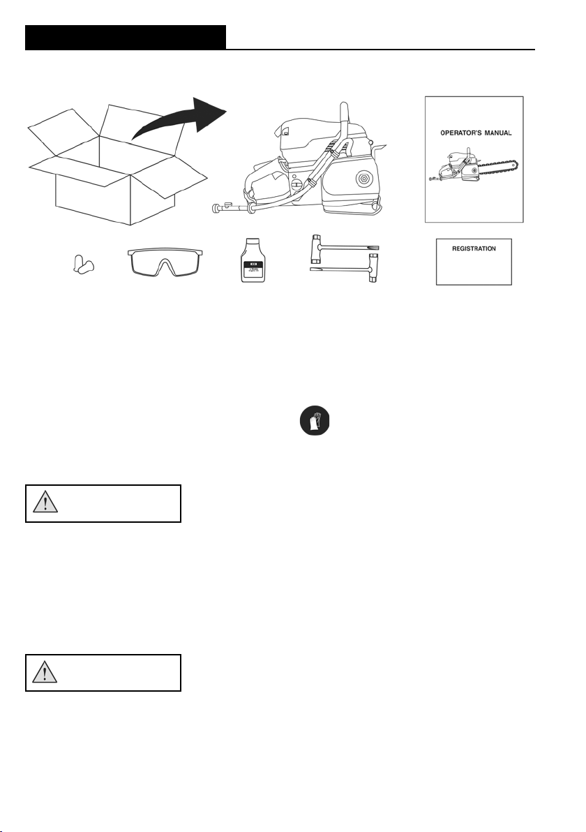
BOX CONTENTS
Minimum contents for all packages shown. Some packages also contain
guidebar and diamond chain.
See page 44 for listing of compatible guidebars and diamond chain.
GUIDEBAR AND DIAMOND CHAIN
INSTALLATION & TENSIONING
Following are the basic instructions for guidebar and diamond chain installation
and tensioning.
WARNING
Never perform any maintenance or adjustments on the saw while the engine is
running.
Be sure the on/o control is locked in the “STOP” position before proceeding.
Improper chain tension can lead to failure of the chain or derailing of the chain
o of the guidebar.
Check tension frequently and adjust if drive links of chain hang 18 mm (3/4 in) or
more below the guidebar groove
CAUTION
Always wear gloves when handling the bar and chain.
These components can develop sharp edges and cause cuts.
© 2016 ICS®, Blount International Inc. Specications are subject to change
16 17
without notice. REV030816 F/N 577452
Page 17

GUIDEBAR AND DIAMOND CHAIN
INSTALLATION & TENSIONING
STEP 1
Loosen side cover nut and remove side cover.
Unpacking & Assembly
STEP 2
Place guidebar slot over bar stud and alignment
block, ensuring even contact with bar pad.
© 2016 ICS®, Blount International Inc. Specications are subject to change
without notice. REV030816 F/N 577452
Page 18

Unpacking & Assembly
695XL OPERATOR MANUAL 695XL OPERATOR MANUAL
GUIDEBAR AND DIAMOND CHAIN INSTALLATION & TENSIONING
STEP 3
Mount the diamond chain on the guidebar starting
at the drive sprocket and continue over the
guidebar nose.
NOTE: FORCE4® requires rim to be pulled outward
for chain installation.
STEP 4
Install the side cover and assure tensioning
adjustment pin engages in the mating hole in
the guidebar. Tighten side cover nut finger tight,
but do not fully tighten until chain is properly
tensioned.
NOTE: To ease assembly, turn tensioning screw
fully counterclockwise before installing side cover.
© 2016 ICS®, Blount International Inc. Specications are subject to change
18 19
without notice. REV030816 F/N 577452
Page 19

Unpacking & Assembly
GUIDEBAR AND DIAMOND CHAIN INSTALLATION & TENSIONING
STEP 5
Make sure all the drive links are inside the
guidebar groove then lift the bar nose and tension
the chain by turning the tensioning
screw clockwise.
STEP 6
Check for proper tension by pulling the chain
around the bar by hand. If you cannot easily pull
by hand, the chain is too tight and needs to be
loosened slightly.
CAUTION: Be aware that the guidebar rails may
develop sharp edges over time so always pull the
diamond chain by the diamond segments.
© 2016 ICS®, Blount International Inc. Specications are subject to change
without notice. REV030816 F/N 577452
Page 20

Unpacking & Assembly
695XL OPERATOR MANUAL 695XL OPERATOR MANUAL
GUIDEBAR AND DIAMOND CHAIN INSTALLATION & TENSIONING
STEP 7
Continue to lift up on the nose of the guidebar and
firmly tighten the side cover nut.
NOTE: Tighten the side cover nut to 27-33 Nm
(20 -25 f t-lbs).
CHAIN TOO TIGHT
STEP 8
Correct chain tension is achieved when drive links
of chain hang just outside of the bar groove. Chain
CHAIN TOO LOOSE
should move freely around guidebar by hand.
© 2016 ICS®, Blount International Inc. Specications are subject to change
20 21
without notice. REV030816 F/N 577452
Page 21

Unpacking & Assembly
CHECKING & ADJUSTING CHAIN TENSION
All chains have a tendency to stretch when used. ICS chains stretch more than
wood cutting chains because of the abrasive materials they are cutting.
WARNING
Improper chain tension can lead to failure of the chain or derailing of the chain
o of the guidebar.
Check chain tension frequently and adjust if drive links of chain hang 18 mm (3/4 in)
or more below the guidebar.
CAUTION
Assure that proper chain tension is maintained.
If tension is set too tight, it will lead to excessive chain stretch, and most of the
saw’s power will be used just to overcome friction. In severe cases the chain may
not turn at all, and can lead to chain breakage. If the tension is set too loose, the
chain could be thrown o of the bar, or allow the sprocket to turn without turning
the chain, which will damage the drive links.
IMPORTANT
When a chain stretches to a point where the drive links are hanging approximately
12 mm (1/2 in) to 18 mm (3/4 in) below the guidebar groove, it is time to tension
the chain.
© 2016 ICS®, Blount International Inc. Specications are subject to change
without notice. REV030816 F/N 577452
Page 22

Unpacking & Assembly
695XL OPERATOR MANUAL 695XL OPERATOR MANUAL
CONNECT TO WATER SUPPLY
Following are the basic instructions to assure correct water supply to the saw.
WARNING
ICS diamond saws require a continuous water supply to the guidebar and
chain.
A key purpose of the supply water is dust suppression. The potential for airborne
particulates depends on many factors including, but not limited to, the material
being cut, application and cutting environment. In all cases, assure that
the water supply is capable of delivering 1.5 bar (20 psi) pressure to the saw at a
minimum ow rate of 4 lpm (1gpm).
NOTE: Local and/or regional regulation can vary widely. It is the responsibility of the
operator to wear appropriate dust protection applicable in their area and suitable to
the application.
Never operate saw with insucient water supply.
Insucient water supply will result in excessive wear to the chain, which can
lead to excessive stretch, chain breakage and/or damage to the guidebar nose
sprocket.
Attach to water supply capable of delivering 1.5 bar
(20 psi) pressure to the saw at a minimum flow rate
of 4 lpm (1 gpm). The single most important factor
an operator can control to increase chain life is to
use adequate water pressure.
© 2016 ICS®, Blount International Inc. Specications are subject to change
22 23
without notice. REV030816 F/N 577452
Page 23

Fueling
FUELING
Following are the basic instructions to assure safe fueling procedures.
DANGER
Fuel vapors are highly ammable.
Turn o the saw, lock the o/on switch in the “STOP” position, and allow the
engine to cool a few minutes before fueling. Do not smoke or refuel the saw in
close proximity to any ignition sources. Move the saw at least 3 m (10 ft) from the
fueling area before restarting it.
IMPORTANT
FUEL
ICS saws require the use of high quality, 90 Octane (95 RON) or higher fuel
combined with ICS 2-stroke oil (or other high quality 2-stroke oil) specically
formulated for air-cooled power equipment at a mixture of 2% (50:1). Due to the
heavy duty cycle ICS saws are subjected to in both concrete and utility pipe
cutting applications, oil mixture and fuel quality are critical to the performance and
life of the engine.
BLENDED AND ALKYLATE FUELS
Pre-mixed (2% oil mixture) alkylate fuel (i.e. Aspen 2) is an acceptable alternative to
conventional fuel.
NOTE: If using Aspen alkylate fuel or similar, carburetor adjustments are not
necessary or recommended.
ETHANOL BLENDED FUEL
While ICS recommends using fuel that does not contain ethanol (alcohol), it is
understood that 10% Ethanol blended fuel (E10) is becoming more widespread.
ICS saws are not designed to operate with fuel containing more than 10% ethanol.
NOTE: The use of Ethanol blended fuel greater than E10 will cause improper
operation and will cause major engine failure. This type of fuel related failure is not
covered under warranty.
This saw is certied to be in conformance with Section 213 of the Clean Air Act
by the US EPA.
Failure to follow instructions on preparing the fuel and oil mixture may result in
emissions violations.
© 2016 ICS®, Blount International Inc. Specications are subject to change
without notice. REV030816 F/N 577452
Page 24

Fueling
695XL OPERATOR MANUAL 695XL OPERATOR MANUAL
FUEL MIXING INSTRUCTIONS
CAUTION
Pressure can build up in the fuel tank and container and possibly cause sudden
release of fuel vapors when the tank is opened.
Open the fuel cap slowly and always provide adequate ventilation when
handling fuel.
IMPORTANT
It is important to accurately measure the amount of oil to be mixed with petrol to
assure that the correct mixture is obtained. When mixing small amounts of fuel,
even small inaccuracies can drastically aect the ratio of the mixture.
Always mix petrol and oil in a clean container approved for use with fuel. Keep fuel
container closed tightly to prevent moisture from getting into the fuel. Do not mix
more than one month’s supply of fuel. This helps prevent the separation of the
2-stroke oil from the petrol (varnishing).
Before fueling, clean the area around fuel cap on the saw to prevent dirt from
contaminating the fuel. Contamination of the fuel tank can lead to saw malfunction.
Always begin mixing fuel by pouring half the amount of petrol to be prepared into
the mixing container. Then add the correct amount of 2-stroke oil for 2% (50:1)
mixture and nish by adding petrol to obtain the total quantity of mixed fuel. Shake
the fuel container to thoroughly mix the petrol and oil before adding to the saw.
The table below shows the correct quantity of two-cycle oil to be used.
FUEL MIXTURE: 2% (50:1) mixture petrol/oil.
PETROL OIL
US Gallon US Fl oz
1 2.6
2 1/2 6.4
5 12.8
NOTE: If the saw is not used for an extended period of time (3 months) the fuel tank
should be emptied and cleaned.
© 2016 ICS®, Blount International Inc. Specications are subject to change
24 25
without notice. REV030816 F/N 577452
PETROL OIL
Liters ml
1 20
5 100
10 200
20 400
Page 25

Fueling
FUELING THE SAW
CAUTION
Do not overll the fuel tank.
Should any fuel spill happen, wipe up the spillage and allow the rest to evaporate.
If fuel is spilled on yourself or your clothes, immediately remove contaminated
clothing and wash any part of your body that has contacted fuel with soap and
warm water.
Pressure can build up in the fuel tank and container and possibly cause sudden
release of fuel vapors when the tank is opened.
Open the fuel cap slowly and always provide adequate ventilation when
handling fuel.
After adding fuel, carefully install the fuel cap and tighten rmly by hand. Tip the
saw slightly to one side and check for leaks. Should any fuel leaks be observed, do
not start the saw.
Customers are encouraged to remain consistent in the fuel option they choose for
ICS saws. Alternating between options, such as going between traditional fuel to
Alkylate fuel (Aspen) and back again may have negative impacts on the engine.
© 2016 ICS®, Blount International Inc. Specications are subject to change
without notice. REV030816 F/N 577452
Page 26

Operation
695XL OPERATOR MANUAL 695XL OPERATOR MANUAL
OPERATION
Following are the basic instructions to assure safe operation of the saw.
WARNING
Never start the saw without the bar, chain and side cover properly assembled.
DO NOT operate the saw with loose, missing, damaged or improperly
installed or repaired parts.
Check that the components shown below are intact, undamaged, and installed
correctly:
• Side cover nut torqued down properly
• Side cover not damaged and discharge port not plugged
• Handles not loose, gripping area is clean and undamaged
• Mud ap is not ripped, torn or missing and fully attached to the saw
• Cylinder cover is properly secured in place
• Muer not damaged and is adequately secured to cylinder
• Guidebar not bent or otherwise damaged such as rails dished and uneven
• Nose sprocket not excessively worn or broken, and turns freely
• Diamond chain does not have loose rivets, chassis damage, or missing
diamond segments
• Chain tensioner mechanism functions properly and pin is not bent or broken
• Drive sprocket not excessively worn and slides easily on adapter
• Check alignment of drive sprocket and guidebar
© 2016 ICS®, Blount International Inc. Specications are subject to change
26 27
without notice. REV030816 F/N 577452
Page 27

Operation
PRE-OPERATION SAFETY CHECKS
Perform the following safety checks each day to be sure that the safety features
designed into the saw are functioning properly. If any items are excessively worn or
damaged, replace before use.
• With on/o switch locked in the “STOP” position, without starting saw and with
decompression valve depressed, pull starter rope slowly and inspect for
fraying, wear and abrasion
• Assure vibration isolators are intact
• With engine running and without depressing thottle trigger lockout, pull throttle
trigger and assure continuous chain movement does not occur
• Verify at engine idle speed that the chain does not move
© 2016 ICS®, Blount International Inc. Specications are subject to change
without notice. REV030816 F/N 577452
Page 28

Operation
695XL OPERATOR MANUAL 695XL OPERATOR MANUAL
STARTING & STOPPING THE SAW
WARNING
Be sure that no part of the cutting system is contacting a solid object when
starting the saw.
When the choke and/or throttle advance is engaged for starting, the chain may
move and cause the saw to react if the chain contacts a solid object.
CAUTION
Move the saw at least 3 m (10 ft) from the fueling area before starting it.
Assure that secure footing is established and chain is not contacting any
objects.
When starting the saw, place the saw on clear and level ground.
IMPORTANT
Failure to break-in an engine may result in piston seizure.
It is very important to break-in a new engine to “seat” all moving parts, especially
the piston rings. To break-in the engine, run one full tank of 2% (50:1) fuel at idle,
cycling the throttle every 5 to 10 minutes to prevent loading.
Do not obstruct air intake.
Loose clothing can inadvertently be drawn into air intake and obstruct air ow
which may result in engine stall.
STOPPING THE SAW
To turn the engine o, push the on/o control briey to the right until engine stops.
Once released, control will automatically return to the “START” position. If control is
pushed beyond the detent, it will lock in the “STOP” position and prevent starting.
Close water valve completely.
© 2016 ICS®, Blount International Inc. Specications are subject to change
28 29
without notice. REV030816 F/N 577452
Page 29

Operation
COLD ENGINE STARTING PROCEDURE
1. Assure on/o control is not locked in the “STOP” position.
2. Pull the multi-function lever out, which also sets the throttle advance.
3. Depress primer/purger bulb until fuel is visible in bulb. May take 10 or more
pushes.
4. Push in decompression valve.
5. Open the water valve 1/4 turn.
6. Place foot on the base of the rear handle, and place one hand on front handle.
7. With opposite hand, slowly pull starter handle until you feel the starter pawls
engage.
8. Pull the starter cord (hard, fast, short pulls) until engine initially res or “pops”.
Could be as many as 10-15 pulls.
9. Push the multi-function lever in, this will keep throttle in advance position.
10. Pull the starter cord until engine starts - should be 1 to 2 pulls.
11. Release the throttle advance by pulling and releasing the throttle trigger, which
allows engine to return to normal idle speed.
12. Allow the engine to idle briey then pull throttle trigger several times to help
warm up the engine.
13. Open the water valve completely.
WARM ENGINE STARTING PROCEDURE
1. Assure on/o control is not locked in the “STOP” position.
2. Pull multi-function lever out, and immediately push back in to set the throttle
advance. If the multi-function lever is left in the out position on a warm engine,
the carburetor will ood with petrol. If this occurs, see Troubleshooting section.
3. Push in decompression valve.
4. Open the water valve 1/4 turn.
5. Place foot on the base of the rear handle, and place one hand on front handle.
6. With opposite hand, slowly pull starter handle until you feel the starter pawls
engage.
7. Pull the starter cord until engine starts. Should be 1-2 pulls.
8. Release the throttle advance by pulling and releasing the throttle trigger, which
allows engine to return to normal idle speed.
9. Allow the engine to idle briey then pull throttle trigger several times to help
warm up the engine.
10. Open the water valve completely.
© 2016 ICS®, Blount International Inc. Specications are subject to change
without notice. REV030816 F/N 577452
Page 30

Operation
695XL OPERATOR MANUAL 695XL OPERATOR MANUAL
PRECUT CHECKLIST
WARNING
Sudden contact of the guidebar nose with a foreign object may generate
kickback.
Remove and/or avoid any obstructions (plumbing, water supply hoses, electrical
conduit, air ducts, etc.) that may interfere with the cut.
To avoid electrocution, check for live electrical wires.
Wires may be hidden within or behind walls and/or laying around the workspace.
Assure that any ancillary electrical equipment (fans, pumps, vacuums, etc.) are
properly grounded and certied for use in the intended environment.
Always operate the saw with solid footing and both hands on the saw.
Keep your left hand on the front handle and your right hand on the rear handle.
Wrap your thumbs around the handles to assure you maintain a secure grip on
both handles.
Never operate the saw during severe inclement weather.
Freezing conditions, lightening and sudden downpours can create hazardous job
site conditions.
Always wear protective clothing.
At a minimum always wear eye protection and/or face shield, hearing protection,
long sleeve shirt, long pants, closed toe shoes with non-slip soles, and gloves. In
many work situations, a hard hat, steel toed shoes and a respirator may also be
required. Avoid loose tting clothing.
Cutting with the saw may generate sparks, especially when cutting through
metal (such as rebar), and may start a re in combustible materials such as dry
grass, wood and fuel.
Be sure to use adequate water pressure and have re ghting equipment readily
available.
© 2016 ICS®, Blount International Inc. Specications are subject to change
30 31
without notice. REV030816 F/N 577452
Page 31

Operation
CUTTING WITH THE SAW
WARNING
DO NOT insert the guidebar into a slot narrower than the width of the chain.
Rapid pushback, kickback and/or chain breakage could result.
Be sure cut concrete cannot fall and injure the operator or bystanders.
Assure cut piece is controlled and does not fall unexpectedly.
NOTE: Concrete is very heavy; one cubic foot = 30 cm x 30 cm x 30 cm = 68 kg (12
in x 12 in x 12 in = 150 lbs).
CAUTION
Slippery or unstable surfaces such as ladders may cause a loss of balance or
control of the saw.
Always keep proper footing and operate the saw only when standing on xed,
secure and level surface.
Unexpected loss of control of the saw and loss of balance can result in injury.
Do not overreach and do not cut above shoulder height.
Do not allow workpiece to pinch the guidebar and chain, or rapid pushback
could result.
Always cut bottom of opening rst and assure workpiece is secure and does not
shift during cutting operations.
Do not operate saw upside down.
Cutting debris can be directed back towards the operator.
Take special precautions when cutting in horizontal orientation.
Be aware that debris may be ejected dierently than when cutting in a vertical
position.
IMPORTANT
Always operate saw at full throttle.
For best results, always operate the saw at full power.
© 2016 ICS®, Blount International Inc. Specications are subject to change
without notice. REV030816 F/N 577452
Page 32

Operation
695XL OPERATOR MANUAL 695XL OPERATOR MANUAL
CUTTING WITH THE SAW
To assure the best performance from your ICS saw, follow all safety precautions
and recommended techniques. Additional helpful information can be obtained at
icsdiamondtools.com.
CONCRETE/MASONRY CUTTING
Planning the Cut
1. Select the proper chain type for the material being cut. Refer to the chain
selection guide in this manual. See page 44.
2. Outline the cut with a permanent marker for a visual cutting guide.
3. Avoid pinching the guidebar and chain by using shims or
other anchoring devices to stabilize the workpiece. Always
plan to cut the bottom of an opening rst, then
top or sides. Save the easiest cut for last (see
image at right).
4. Be sure cut concrete cannot fall and injure the operator
or bystanders. As the cut is being completed, assure that
appropriate bracing is in place to control the cut section
of the workpiece. Concrete is very heavy,
one cubic foot = 30 cm x 30 cm x 30 cm = 68 kg (12 in x 12 in x 12 in = 150 lbs)
.
3
22
1
© 2016 ICS®, Blount International Inc. Specications are subject to change
32 33
without notice. REV030816 F/N 577452
Page 33

CONCRETE/MASONRY CUTTING
Recommended Concrete Cutting Techniques
1. Plunge in
2. Cut down to open slot
3. Insert WallWalker® rotate rear handle up
Operation
4. Pull saw out, rotate rear handle down,
press bottom of saw to leading edge of cut
and rotate rear handle up
5. Reengage WallWalker® and repeat Steps
3 and 4
© 2016 ICS®, Blount International Inc. Specications are subject to change
without notice. REV030816 F/N 577452
Page 34

Operation
695XL OPERATOR MANUAL 695XL OPERATOR MANUAL
CUTTING TIPS
• For the straightest cuts use the “Step Cut” method:
• First score the entire cut line approximately a 12 mm (1/2 in) deep
using the nose of the guidebar
• Next, deepen the cut by about two inches
• Then plunge all the way through and complete the cut using the
WallWalker® as a pivot point and pull on the rear handle to rotate the
bar into the cut
• Always operate the concrete saw at full throttle. If too much force is
applied, the saw will lug or stall. The chain will not have enough speed to cut
eectively. If too little feed force is applied, the diamonds will skid and glaze
over.
• Plunge cut instead of starting at the top surface of the wall. This will reduce
chatter, extend diamond life, create a straighter cut and more quickly enable
the use of the WallWalker.
• When cutting heavy rebar, slowly “rock” the saw so that you’re always cutting
concrete as well as steel. This will help keep the diamonds exposed. Also,
expect less chain life when cutting heavy rebar.
• Expect more chain stretch when making nose-buried cuts for extended
periods of time, as the chain does not have a chance to “throw” the slurry
away from the nose of the guidebar.
• If the saw begins to cut consistently crooked, stop the saw, remove the bar and
chain and turn the bar over and use the other side. Dress worn rails with a belt
sander.
Note: The normal life of a guidebar is two to three diamond chains. Heavy rebar
can shorten guidebar life.
• The guidebar is solely a guide track for the chain. Never use the guidebar to lift,
twist or pry concrete material
• When using a new chain, you can increase the initial cutting speed by “opening
up the diamonds”. This can be accomplished by rst making a few cuts in an
abrasive material such as a cinder block or brick.
© 2016 ICS®, Blount International Inc. Specications are subject to change
34 35
without notice. REV030816 F/N 577452
Page 35

Operation
PIPE CUTTING USING
POWERGRIT® UTILITY SAW CHAIN
To assure the best performance from your ICS® saw when cutting ductile iron pipe
or similar pipe materials, follow all safety precautions and recommended cutting
techniques.
WARNING
Always assure trench walls are adequately supported before entering work space.
Consult applicable regional regulations and obtain necessary approvals before entering
a trench or any excavated areas.
Never attempt to cut ductile iron pipe or similar pipe materials with the saw
unless using PowerGrit® Utility Saw Chain. Using concrete diamond saw chain in
these applications can cause the chain to snag abruptly in the cut which may result in
chain breakage, pushback and/or kickback.
Always assure that pipe is properly evacuated before cutting.
Pipes may contain sewage, gas or other hazardous materials.
Always support the pipe on both sides of the cut to assure the cut remains open
throughout the cutting operation, including when the cut is nished.
An improperly supported pipe can cause the cut to close, pinching the chain and
guidebar which may result in chain breakage, pushback and/or kickback.
Recommended Pipe Cutting Techniques
1. Make a small plunge cut into the lower quadrant of
the pipe to relieve internal pressure and allow contents
to drain from pipe in a controlled manner.
2. With pipe drained, cut from the top of pipe and
continue through bottom of the pipe.
3. To assure straightness of cut, guidebar should
extend completely through the pipe during the cut.
4. To assist with cutting, engage the WallWalker®
in the cut when possible to provide additional
leverage and alternate cutting between the near and
far side walls of the pipe.
© 2016 ICS®, Blount International Inc. Specications are subject to change
without notice. REV030816 F/N 577452
Page 36

Transporting & Storing
695XL OPERATOR MANUAL 695XL OPERATOR MANUAL
TRANSPORTING & STORING
WARNING
Fuel and vapors are highly ammable
When transporting or storing fuel, always use a container approved for fuel and
assure it is sealed against leaks and/or escaping fumes. Contact with an ignition
source could cause re or explosion.
CAUTION
Always carry the saw by the front handle with the on/o control in the locked
“STOP” position and away from your body
When transporting the saw, assure it is secured to avoid damage and/or personal
injury. Proper handling of the saw will reduce the likelihood of accidental contact
with the guidebar and chain.
IMPORTANT
ICS recommends mixing fuel in small batches, to be used within 30 days. Fuel
stabilizers (additives) can prolong the life of the fuel, but still should not be stored
longer than 90 days.
© 2016 ICS®, Blount International Inc. Specications are subject to change
36 37
without notice. REV030816 F/N 577452
Page 37

Maintenance
MAINTENANCE
AFTER EACH USE
IMPORTANT
1. After cutting, pull trigger to spin the chain for at least 15 seconds with the
water on to ush slurry and debris from chain, guidebar and drive sprocket.
2. Stop saw and wash concrete slurry from saw assembly with special attention
to the starter housing and ywheel. Do not let slurry dry on saw as it will be
very dicult to remove later.
3. Avoid getting any water in the carburetor or exhaust system. If water enters
the exhaust port, it can enter the carburetor. To make sure there is no water in
the exhaust system, assure the on/o control is locked in the “STOP” position,
point the guidebar tip down and pull the starter handle several times to expel
water from muer.
4. Remove the chain and guidebar. Flush out the chain tensioner and side cover
with water. Lubricate tensioner with waterproof grease.
5. After cleaning the saw, spray the entire saw body, chain, guidebar, and drive
sprocket with lightweight oil. Using lightweight oil on the saw will minimize rust
and help reduce slurry build up.
6. Inspect and tighten all fasteners as necessary.
7. Inspect drive sprocket for wear. Replace if tooth tips are pointed, or if groove
cuts through top of tooth.
8. Check clutch cup needle bearing for wear. Assure clutch cup spins freely and
without excessive play.
9. Check starter cord for wear or damage. Replace as necessary.
10. Inspect air lter. Replace lter if dirty or wet.
11. Spray lightweight oil into the air intake slots on the starter housing and ywheel
(this will prevent the starter pawls from sticking).
AFTER EVERY 10 HOURS OF USE
1. Remove the starter cover and clean the ywheel ns and the starter pawls with
a wire brush, then apply waterproof grease to the starter pawls.
2. Remove the spark plug and clean with a wire brush. Check the electrode gap.
The correct gap is 0.5 mm (0.020 in). Replace if necessary.
AFTER EVERY 40 HOURS OF USE
1. Change the spark plug. Adjust the electrode to 0.5 mm (0.020 in).
2. Check the fuel lter located inside the fuel tank. Clean or replace if clogged.
© 2016 ICS®, Blount International Inc. Specications are subject to change
without notice. REV030816 F/N 577452
Page 38

Maintenance
After each use After every 10 hours After every 40 hours
External Cleaning Clean Starter Housing Replace Spark Plug
Fasteners/Screws Check Spark Plug Check Fuel Filter
Air Intake
Functional Inspection Functional Inspection Functional Inspection
General Inspection Vibration Isolators Fuel System
Throttle Trigger Lockout Muer Fuel Filter
On/O Switch Carburetor Air Filter
Mud Flap Starter Housing Clutch Cup
Guidebar and Chain Sprocket Clutch
695XL OPERATOR MANUAL 695XL OPERATOR MANUAL
AIR FILTER
The polyester air lter must be kept clean for the
engine to operate properly. If the saw is not reaching
full RPM, most likely the air lter is dirty or wet.
• The air lter should be free of holes and white
in color
• Replace the air lter when dirty or wet
• When replacing the air lter, clean the area inside
the air box with a clean towel prior to installing
new lter
• Inspect air box seals for wear or damage. Replace if damaged
FUEL SYSTEM
• Clean area around fuel cap before removing
• Check the fuel cap and seal for damage
• Check the fuel line for damage
• Check fuel lter, assure it is free of debris
• Replace fuel lter if it is stained dark or clogged (fuel lter cannot be cleaned)
© 2016 ICS®, Blount International Inc. Specications are subject to change
38 39
without notice. REV030816 F/N 577452
Page 39

Maintenance
SPARK PLUG
• Clean the spark plug with a wire brush and check to assure the plug gap is 0.5
mm (0.020 in)
• Inspect the spark plug boot, replace if needed
• Inspect lead wire for wear or damage. Replace if necessary (lead wire cannot
be replaced separately from ignition module)
IMPORTANT
• Replace spark plug after 40 hours of use, or if the electrode is corroded or
eroded
• Always use a recommended spark plug (resistor type) to prevent damage to
the piston and cylinder (NGK #BPMR7A or Champion RCJ6Y or equivalent)
CARBURETOR
• The function of the carburetor is to mix fuel with air. Adjustments other than
idle speed should only be made by an Authorized Service Center
• Before adjusting the engine idle speed, make
sure the air lter is clean, the engine is running,
warmed up and the guidebar and chain are
assembled on the saw
• Adjust idle screw so that the engine idles smoothly
but the clutch does not engage. If the chain begins
to spin, turn the idle screw counter-clockwise until the
chain stops
• If saw has been running satisfactorily and there is a
gradual decrease in power and drop in RPM at full
throttle, the lter may have become dirty or wet. (See
air lter section)
Carburetor idle screw
STARTER RECOIL HOUSING
It is common for concrete slurry to get inside the starter
housing assembly during cutting. This can cause starter
pawls to stick and not engage when the rope is pulled.
• After each usage, thoroughly ush the starter housing
assembly with water
• Spray lightweight oil into the air intake slots on the
starter housing and ywheel (this will prevent the starter pawls from sticking)
• Inspect the starter cord for fraying, replace if necessary
© 2016 ICS®, Blount International Inc. Specications are subject to change
without notice. REV030816 F/N 577452
Page 40

Maintenance
695XL OPERATOR MANUAL 695XL OPERATOR MANUAL
STARTER ROPE REPLACEMENT
• Loosen the four screws that attach the starter cover assembly to the
crankcase, and remove the starter cover assembly from the saw
• Pull rope out from pulley approximately 30 cm (12 in)
and hook rope into the notch in the pulley. Relax
the recoil spring by placing thumb on the pulley
and gently allow the pulley to rotate
backwards to unwind the spring entirely
• Loosen center screw to remove pulley from starter
recoil housing and remove the old starter rope
• Thread new starter rope through hole in the starter
recoil housing and then through hole in pulley
• Wrap the starter rope counter clockwise around
the raised center of the pulley, looping over top
and under the beginning of the wrap. Tighten the
knot rmly and assure that free end of rope is as short as possible. Secure the
other end of the rope in the starter handle
• Reinstall pulley in starter recoil housing and tighten center screw
TENSIONING THE RECOIL SPRING
• Hook the rope in the notch of pulley and wind the rope clockwise three times
around the raised center of the pulley
• Pull the starter rope with the handle until the rope is unwound, tensioning the
spring. Repeat this process, but this time, wind the rope clockwise four times
around and then pull the rope with the handle to complete the tensioning of
the spring
NOTE: When released, the starter handle should be drawn to the correct start
position after tensioning the spring.
IMPORTANT
Check that the pulley can be turned an additional 1/2 turn when the starter cord
is pulled all the way out.
© 2016 ICS®, Blount International Inc. Specications are subject to change
40 41
without notice. REV030816 F/N 577452
Page 41

Maintenance
STARTER RECOIL HOUSING ASSEMBLY
• To reattach the starter cover assembly, rst pull the
starter cord out, then hold the starter recoil housing
against the crankcase
• Slowly release the starter cord to enable the pulley
to t between the pawls
• Insert and tighten the screws. Use blue Loctite®
#242
CHAIN TENSIONER
The chain tensioner can become clogged with concrete slurry during cutting.
• After each use thoroughly ush the chain tensioner with water and apply a
liberal amount of waterproof grease covering the chain tensioner screw
NOTE: The chain tensioner is located on the side cover.
Chain Tensioner
Chain Tensioner
© 2016 ICS®, Blount International Inc. Specications are subject to change
without notice. REV030816 F/N 577452
Page 42

Maintenance
695XL OPERATOR MANUAL 695XL OPERATOR MANUAL
DRIVE SPROCKET
• The drive sprocket (rim sprocket) is a wear
item and should be replaced every two to
three chains, or when the teeth become
pointed or if groove cuts through top of
tooth.
• Inspect the sprocket for wear
• The needle bearing inside of the clutch cup
is self-lubricating through the crank shaft,
spin the clutch cup to assure it spins freely
and without excessive play
Clutch Cup
DRIVE SPROCKET REMOVAL/INSTALLATION
Drive Sprocket
Half Collar
Spring Clip
Retaining Washer
Splined Adapter
CAUTION
Wear safety glasses.
• Remove the side cover, diamond chain and guidebar
• Using a screwdriver, carefully pry the spring clip from the half collars.
NOTE: Cup your hand over the end of shaft to prevent spring clip from being
ejected.
• Remove the half collars and retaining washer from the shaft
• Slide the drive sprocket o of the splined adapter
• Reengage the clutch cup onto the shaft and slide the drive sprocket onto the
splined adapter, either side out
• Install the retaining washer and half collars onto the shaft
• Place the spring clip atop the half collars, assuring the half collars are
symmetrical with equal gap on either side
• Engage the spring clip onto the half collars by
rmly pressing down with a screwdriver over
top of one of the gaps
NOTE: Hold your thumb on the spring clip over the
opposite side gap to maintain placement.
• Once the spring clip is partially engaged on
one side, perform the same technique to
the other side, again pressing rmly over
top of the gap
• Visually check proper spring clip engagement
in groove of half collars. Both half collars should be
rmly secured to the shaft
© 2016 ICS®, Blount International Inc. Specications are subject to change
42 43
without notice. REV030816 F/N 577452
Page 43

Maintenance
CHAINS & GUIDEBARS
IMPORTANT
Inspect chain segments and drive links for damage or excessive wear. Chains
with damage or excessive wear should not be used or repaired, they should be
replaced.
NOTE: Guidebars are designed to be used on both sides. If the cut is consistently
leading to one side, turn the guidebar over. It is recommended to turn the guidebar
over with every new chain.
• A table mounted belt or disc sander can be used to square the rails of a worn
guidebar. A badly worn guidebar can quickly damage the chain. If the chain is
touching the bottom of the guidebar groove, replace the guidebar
• Check the guidebar for straightness
• Proper chain tension will extend guidebar life
• Under some circumstances, especially low water pressure, the sprocket nose
can wear out before the guidebar body. Sprocket nose assemblies may be
replaced by an Authorized Service Center
• Periodically clean the water ports inside the groove of the guidebar using a
small diameter piece of wire or pipe cleaner
• The guidebar is solely a guide track for the chain. Never use the guidebar to lift,
twist or pry concrete material
• Prior to storage, spray the chain and guidebar with lightweight oil
© 2016 ICS®, Blount International Inc. Specications are subject to change
without notice. REV030816 F/N 577452
Page 44

Maintenance
695XL OPERATOR MANUAL 695XL OPERATOR MANUAL
695XL CHAIN SELECTION GUIDE & CONSUMABLES
3/8” Pitch Chain Selection Guide
Chain &
Applications
™
TwinMAX
General Purpose
™
Plus
TwinMAX
For harder materials
TwinMAX™ Abrasive
For brick & block
Soft Stone/
Abrasive/Brick
◊
Natural Stone
◊ ◊
◊ ◊ ◊
Medium
Concrete/Light
Reinforcement
3/8” Pitch Consumables
30 cm (12 in) 35 cm (14 in) 40 cm (16 in)
™
Diamond Chain p/n 71400 p/n 71486 p/n 71607
TwinMAX
TwinMAX™ Plus Diamond Chain p/n 71704 p/n 71705 p/n 71706
™
Abrasive Diamond Chain p/n 71554 p/n 71610 p/n 71611
TwinMAX
3/8” Pitch Guidebar p/n 553207 p/n 73600 p/n 71600
3/8” Pitch Drive Sprocket p/n 70949
Hard
Concrete/ Heavy
Reinforcement
Ductile Iron/Cast
Iron/PVC/HDPE
© 2016 ICS®, Blount International Inc. Specications are subject to change
44 45
without notice. REV030816 F/N 577452
Page 45

TROUBLESHOOTING
PROBLEM Possible Cause
SAW WON'T REACH FULL RPM Dirty air filter
Troubleshooting
SLOW CHAIN SPEED
POOR CUTTING SPEED
PREMATURE CHAIN STRETCH
CHAIN TENSIONER BREAKAGE
WATER NOT FLOWING
WON'T START
DIFFICULT TO START
Chain tension too tight. Chain should always be able to
be pulled around the guidebar by hand. It is normal for the
drive links of the chain to hang below the guidebar.
All of the above, plus diamonds may be glazed over. Make
a few cuts in an abrasive material to expose the diamonds.
Not enough water pressure. The minimum water pressure
required is 1.5 bar (20 psi). Insufficient water supply may
result in excessive wear to the chain, which can lead to
stretch and chain breakage.
Side cover nut is not tight enough. Torque to 27-33 Nm
(20-25 ft-lbs ).
Tensioning with side cover nut already tight
Water hose is kinked or water supply not turned on
Water ports plugged with debris
Aged or bad fuel
Corroded or eroded spark plug
Stop switch locked in "STOP" position
Flooded engine. Push Multi-function lever in, hold throttle
on full with foot and pull starter cord (hard, short, fast pulls)
until engine starts.
Fouled spark plug. Remove spark plug, clean, and re-gap
to 0.5 mm (0.020 in).
Improper chain tension
Insufficient water pressure
CHAIN BREAKAGE
© 2016 ICS®, Blount International Inc. Specications are subject to change
without notice. REV030816 F/N 577452
Inserting saw into slot narrower than diamond chain
segments
Using chain that is already stretched beyond ability to
tension
Page 46

695XL OPERATOR MANUAL 695XL OPERATOR MANUAL
THIS PAGE INTENTIONALLY LEFT BLANK
© 2016 ICS®, Blount International Inc. Specications are subject to change
46 47
without notice. REV030816 F/N 577452
Page 47

Emissions
FEDERAL EMISSION CONTROL WARRANTY STATEMENT
YOUR WARRANTY RIGHTS AND OBLIGATIONS
The U.S. Environmental Protection Agency (EPA), Environment Canada and
ICS, Blount Inc. are pleased to explain the Emissions Control System Warranty
on your 2009 and later small non-road engine. In the U.S. and Canada, new
small non-road engines must be designed, built and equipped to meet federal
emission regulations.
ICS must warrant the emission control system on your small non-road engine
for the period of time listed below provided there has been no abuse, neglect or
improper maintenance of your unit.
Your emission control system includes parts such as the carburetor and the
ignition system. Also included may be hoses, connectors and other emission
related assemblies.
Where a warrantable condition exists, ICS will repair your saw engine at no cost
to you. Expenses covered under warranty include diagnosis, parts and labor.
MANUFACTURER’S WARRANTY COVERAGE
The emission control system on 2009 and later small non-road engines is
warranted for two years. If any emission related part on your engine (as listed
above) is defective, the part will be repaired or replaced by ICS.
© 2016 ICS®, Blount International Inc. Specications are subject to change
without notice. REV030816 F/N 577452
Page 48

Emissions
695XL OPERATOR MANUAL 695XL OPERATOR MANUAL
FEDERAL EMISSION CONTROL WARRANTY STATEMENT
OWNER'S WARRANTY RESPONSIBILITIES
As the saw owner, you are responsible for the performance of the required
maintenance listed in your Operator's Manual. ICS recommends that you
retain all receipts covering maintenance on your saw engine, but ICS cannot
deny warranty solely for the lack of receipts or for your failure to assure the
performance of all scheduled maintenance. However, ICS reserves the right to
deny warranty coverage if your saw engine, or a part of it, has failed due to abuse,
neglect, improper maintenance, unapproved modifications or the use of parts
not made or approved by the original equipment manufacturer.
You are responsible for presenting your saw engine to an ICS authorized
servicing dealer as soon as a problem exists. The warranty repairs should be
completed in a reasonable amount of time, typically not to exceed 30 days.
If you have any questions regarding your warranty rights and responsibilities,
please contact an ICS customer service representative at 1.800.321.1240.
www.icsdiamondtools.com
LENGTH OF COVERAGE
ICS warrants to the initial purchaser and each subsequent owner that the engine
is free from defects in materials and workmanship which cause the saw engine to
fail to conform with applicable emission regulations for a period of two years.
WARRANTY PERIOD
The warranty period begins on the date of sale of the saw engine to the initial
purchaser.
© 2016 ICS®, Blount International Inc. Specications are subject to change
48 49
without notice. REV030816 F/N 577452
Page 49

Technical Speccations
TECHNICAL SPECIFICATIONS
Engine Type 2-stroke, Air Cooled
Displacement 94 cc (5.7 cu-in)
Horsepower 4.8 kW (6.4 hp) @ 9000 rpm
Torque 5.7 Nm (50.4 in-lbs) @ 7,200 rpm
Engine Speed
Chain Speed at Maximum Power 28 m/s (5500 ft/min)
Weight 9.5 kg (21 lbs) powerhead only
Dimensions
46 cm (18 in) length 36 cm (14 in) height
Air Filter Water resistant polyester
Carburetor Walbro RWJ-7
Starter Recoil, dust and water resistant
Ignition Special water resistant electronic ignition
Clutch Centrifugal, three shoe, three spring
9,300 +/- 150 rpm (max)
2,700 +/- 100 rpm (idle)
30 cm (12 in) width
Fuel ratio 2% (50:1) petrol-to-oil
Fuel Capacity 1 liter (0.26 gallon)
Water Supply Requirement Minimum 1.5 bar (20 psi)
Water Flow Requirement Minimum: 4lpm (1 gpm )
Guaranteed Sound Power Level, L
Equivalent Sound Pressure at the
Operator's Ear L
Vibration, a
Vibration, a
Concrete Cutting (2)
hv, eq
Pipe Cutting (2)
hv, eq
pA
(1) 115 dB(A); (Kwa=1.0 dB(A))
wa
104.6 dB(A) (K=1.0 dB( A))
3.6 m/s2 (K=1.0 m/s2) Front Handle
3.1 m/s2 (K=1.0 m/s2) Rear Handle
5.62 m/s2 (K=0.2 m/s2) Front Handle
5.28 m/s2 (K=0.2 m/s2) Rear Handle
Engine Break-in Period One tank, without cutting, cycling throttle
Spark Plug
(1) Measured in accordance with ANSI S12.51-2012/ISO3741:2010
(2) Measured in accordance with ISO5349-1:2001, ISO22867:2011 and ISO19432:2012
© 2016 ICS®, Blount International Inc. Specications are subject to change
without notice. REV030816 F/N 577452
NGK BPMR7A or Champion RCJ6Y
Electrode gap 0.5 mm (0.020 in)
Page 50

Service Centers
695XL OPERATOR MANUAL 695XL OPERATOR MANUAL
AUTHORIZED SERVICE CENTERS
DEALER PHONE ADDRESS CITY STATE ZIP CODE
KENNEDY EQUIPMENT CO INC 714.771.7324 748 N. LEMON ST ORANGE CA 92867
ABLE TOOL EQUIPMENT 860.289.2020 410 BURNHAM STREET SOUTH WINDSOR CT 06074
EQUIPSERV LLC 770.709.5101 6225 MABELTON PARKWAY SW MABLETON GA 30126
STAR EQUIPMENT 515.283.2215 1401 2nd AVE DES MOINES IA 50314
MCCANN INDUSTRIES, INC. 630.627.8700 543 SOUTH ROHLWING RD ADDISON IL 60101
CLEAN RITE TECH 504.468.7997 1332 FULTON ST KENNER LA 70062
ACE CUTTING EQUIPMENT 248.449.4944 25806 NOVI RD. NOVI MI 48375
CONCRETE CUTTING & CORING 952.882.0980 12690 CREEK VIEW AVE SAVAGE MN 55378
ACME ELECTRIC 218.628.3523 4332 GR AND AVE DULUTH MN 55807
MERLIN STELZER SALES CO., INC. 314.535.7540 4109 PAPIN ST ST. LOUIS MO 63110
ACME ELECTRIC 701.258.1267 3840 E. ROSSER AVE BISMARCK ND 58501
ACME ELECTRIC 701.746.6481 1705 12TH AVE NORTH GRAND FORKS ND 58203
ACME ELECTRIC 701.476.4600 920 36TH STREET S.W. FARGO ND 58103
ACME ELECTRIC 701.839.2263 700 20TH AVE S.E. MINOT ND 58701
ADMAR SUPPLY 585.272.9390 1950 BRIGHTON-HENRIETTA TL RD ROCHESTER NY 14623
ADMAR SUPPLY 315.433.5000 6014 DROTT DR EAST SYRACUSE NY 13057
ADMAR SUPPLY 518.690.0750 878 ALBANY SHAKER RD LATHAM NY 12110
ADMAR SUPPLY 607.754.4700 2305 OLD VESTAL RD VESTAL NY 13850
ADMAR SUPPLY 716.873.8000 1394 MILITARY RD BUFFALO NY 14217
CESSCO, INC. 503.288.1242 4222 N.E. COLUMBIA BLVD. PORTLAND OR 97218
TRI-BORO CONST. SUPPLIES 800.632.9018 435 LOCUST ST DALLASTOWN PA 17313
LEHIGH CONSTRUCTION SUPPLY CO. 570.654.3981 295 SCHOOLEY AVE EXETER PA 18643
DRIVEKORE, INC. 717.766.7636 101 WESLEY DRIVE MECHANICSBURG PA 17055
ECKHART CONSTRUCTION 803.802.6635 1019 SOCIETY LANE FORT MILL SC 29707
STAN HOUSTON EQUIPMENT 605.336.3727 501 SOUTH MARION ROAD SIOUX FALLS SD 57106
STAN HOUSTON EQUIPMENT 605.348.1155 1210 DEADWOOD AVENUE RAPID CIT Y SD 57702
LINCOLN CONTRACTORS SUPPLY 414.541.1327 11111 WEST HAYES AVE MILWAUKEE WI 53227
LINCOLN CONTRACTORS SUPPLY 608.249.6476 901 WALSH RD MADISON WI 53714
LINCOLN CONTRACTORS SUPPLY 715.359.6111 5207 WESTFAIR AVE SCHOFIELD WI 54476
LINCOLN CONTRACTORS SUPPLY 920.757.1901 5663 NUEBERT RD APPLETON WI 54913
LINCOLN CONTRACTORS SUPPLY 920.432.8697 1654 MORROW ST GREEN BAY WI 54302
LINCOLN CONTRACTORS SUPPLY 715.874.4100 7840 PARTRIDGE AVE EAU CLAIRE WI 54703
LEE JENSEN SALES CO, INC 815 459-0929 101 WEST TERRA COTTA CRYSTAL LAKE IL 60014
ROCK-CRETE EQUIPMENT LTD. 604 464-1448 50 BURBIDGE STREET COQUITLAM BC V3K 6B1
CONCUT DIAMOND PRODUCTS 561-989-8895 6500 W ROGERS CIRCLE SUITE 6000 BOCA RATON FL 33487
AUSTECH SUPPLIES PTY LTD 61298541200 UNIT 12, 197 POWER STREET GLENDENNING NSW 2761
HATCH BUILDING SUPPLY COMPANY 608 222-0011 5601 MANUFACTURERS DRIVE MADISON WI 53704
AMERICAN TOOL AND FASTENER 972-801-9909 1331 E PLANO PKWY STE #B PLANO TX 75074
HENARD UTILITY PRODUCTS, INC 501 268-1987 1920 S. MAIN STREET SEARCY AR 72143
© 2016 ICS®, Blount International Inc. Specications are subject to change
50 51
without notice. REV030816 F/N 577452
Page 51

THIS PAGE INTENTIONALLY LEFT BLANK
© 2016 ICS®, Blount International Inc. Specications are subject to change
without notice. REV030816 F/N 577452
Page 52

695XL OPERATOR MANUAL
ICS | BLOUNT, INC.
4909 SE INTERNATIONAL WAY
PORTLAND, OR 97222
800.321.1240
icsdiamondtools.com
© 2016 ICS®, Blount International Inc. Specications are subject to
change without notice. REV030816 F/N 577452
 Loading...