

ICS SpeedHook 823H, SpeedHook 813M, SpeedHook 853PRO, SpeedHook 880F4, SpeedHook 814PRO Operator's Manual
...Page 1

SpeedHook
Concrete Cutting System
®
OPERATOR’S MANUAL
© 2012 ICS, Blount International Inc. Specications are subject to change without notice. REV1112 F/N 70569
Hydraulic Saws
Page 2

Page 3

TABLE OF CONTENTS
TITLESpeedHook® OPERATOR’S MANUAL
SYMBOLS & LABELS 4
SAFETY 5
TECHNICAL SPECIFICATIONS 6
SET-UP
• 823H / 853PRO / 880F4 7
• 813M / 814PRO 8
OPER ATION 9
CUTTING TIPS 10
TROUBLESHOOTING 11
© 2012 ICS, Blount International Inc. Specications are subject to change without notice. REV1112 F/N 70569
3
Page 4

SYMBOLS & LABELS
THE FOLLOWING SYMBOLS & DEFINITIONS ARE FOUND THROUGHOUT THIS MANUAL AND
ARE DESIGNED TO MAKE YOU AWARE OF POTENTIAL HAZARDS OR UNSAFE PRACTICES.
SpeedHook® OPERATOR’S MANUAL
WARNING
CAUTION
IMPORTANT
THE FOLLOWING SYMBOLS & LABELS MAY BE FOUND IN THIS MANUAL OR ON THE SAW
A potentially hazardous situation exists which, if not avoided,
could result in death or serious injury.
A potentially hazardous situation exists which, if not avoided,
may result in minor or moderate injury or property damage.
A potential situation exists which, if not avoided, may result in
product or property damage.
Read the operator’s manual carefully and understand the
contents before you use this equipment.
Always use:
• Protective helmet
• Ear protection
• Protective glasses or full face protection
Wear hand protection
4
© 2012 ICS, Blount International Inc. Specications are subject to change without notice. REV1112 F/N 70569
Page 5

SpeedHook® OPERATOR’S MANUAL
SAFETY
GENERAL SAFETY PRECAUTIONS
• Always wear protective clothing, including hard hat, eye protection, hearing protection, and
gloves.
• Avoid loose fitting clothing.
• Perform safety checks before starting each day.
• Always operate tool with solid footing and with both hands on saw.
• Remove or control slurry to prevent slippery conditions while cutting.
• Be sure there are no obstructions (plumbing, electrical conduit, air ducts) and no unnecessary
people present.
• Set up a well-marked safety zone with a roped boundary and clear signs.
• Provide adequate ventilation when working in an enclosed area. Breathing exhaust gases is
dangerous.
© 2012 ICS, Blount International Inc. Specications are subject to change without notice. REV1112 F/N 70569
5
Page 6

TECHNICAL SPECIFICATIONS
LCL
C
SpeedHook
SpeedHook® OPERATOR’S MANUAL
L
3.25 in (83 mm)
®
Length 42 in (105 cm)
Width 3.5 in (8.9 cm)
Weight of Rail 18 lbs (8 kg)
Distance from cut line to of
anchors, A
Distance from cut line to
outside rail, B
C
3.25 in (83 mm)
1.5 in (38 mm)
Tools Required:
823H / 853PRO / 880F4 / 890 Series Hydraulic Saws
1. Scrench
701-A Series Pneumatic Saw
1. Scrench
813M & 814PRO Hydraulic Saws
1. 3/16" Allen wrench
2. Pliers
1.5 in (38 mm)
Cut Line
6
© 2012 ICS, Blount International Inc. Specications are subject to change without notice. REV1112 F/N 70569
Page 7

SET-UP
823H / 853PRO / 880F4 HYDRAULIC MOUNTING BRACKET INSTALLATION
TITLESpeedHook® OPERATOR’S MANUAL
STEP 1
®
Remove WallWalker
and spring
STEP 2
Remove side cover (retain side cover
for future use without SpeedHook®)
STEP 4
Tension bar and chain as described
in the 823H / 853PRO / 880F4
operator's manual
STEP 5
Insert axle into mounting backet as
shown and firmly tighten knob
STEP 3
Mount SpeedHook® mounting bracket
over bar mount studs
© 2012 ICS, Blount International Inc. Specications are subject to change without notice. REV1112 F/N 70569
STEP 6
Complete assembly
7
Page 8
TITLE SpeedHook® OPERATOR’S MANUAL
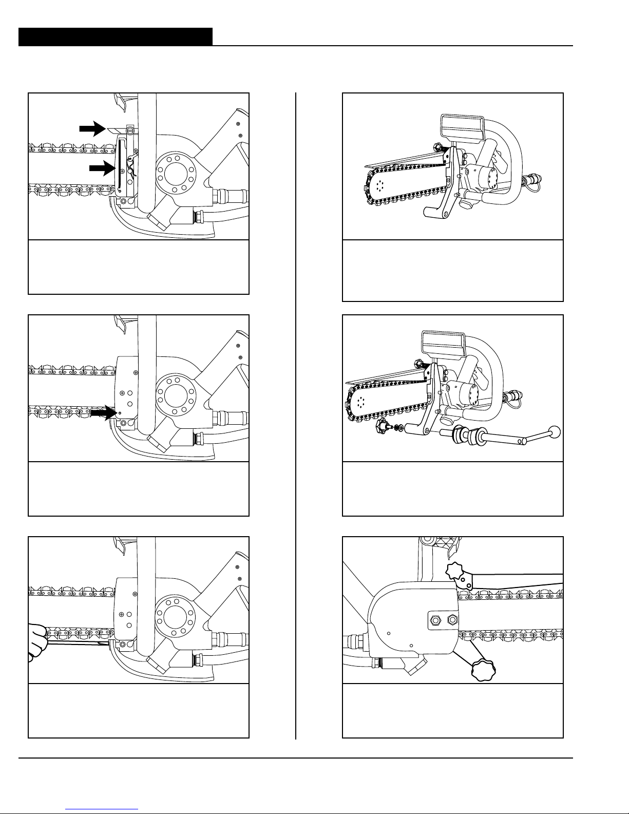
SET-UP
813M & 814PRO HYDRAULIC MOUNTING BRACKET INSTALLATION
STEP 4
STEP 1
Remove WallWalker
®
and spring
Attach SpeedHook
assembly. Note: Do not over tighten
attachment bolts
®
mounting bracket
STEP 2
Remove spring anchor
STEP 3
Remove mud flap and bracket
8
© 2012 ICS, Blount International Inc. Specications are subject to change without notice. REV1112 F/N 70569
STEP 5
Insert axle into mounting bracket as
shown and firmly tighten bolt
STEP 6
Complete assembly
Page 9

TITLESpeedHook® OPERATOR’S MANUAL
OPER ATION
PLANNING THE CUT
The following steps are recommended to maximize cutting efficiency, productivity and
assure safety:
• Outline the cut with a permanent marker.
• Layout concrete anchor marks 3
1
⁄4 inches (8.3 cm) inside each cut line.
• Set the anchors. Caution: The anchor bolts cannot protrude out of the wall more than 3/8 inches
(1 cm) or interference with the SpeedHook® mounting bracket (on the saw) can occur.
• Cutting sequence: Always start with the right-hand side cut first, then the bottom and then the
top. Save the left-hand side cut for last. Using this sequence you will only need to reverse the
axle for the last cut.
• Be sure cut concrete cannot fall and injure operator or bystanders.
• Check for live electrical wiring near cutting areas or in the concrete to avoid electrocution which
can result in death or serious injury.
®
MOUNTING THE SPEEDHOOK
TO WALL
• Loosely attach the rail to the wall so that the horizontal and vertical adjustments can be made.
• Position the rail so that the scribe line near the bottom of the rail is where you want the cut to end.
• Position the outside of the rail exactly 1½ inches (3.8 cm) from the center of the cut line and
securely tighten the anchors, using thick fender washers.
• Do not flex SpeedHook
®
to the wall when gaps exist. Instead, shim gaps between SpeedHook®
and wall.
MAKING THE CUT
• Engage the axle into the hook of the rail near the beginning of the cut.
• Rotate lever arm to engage the cams, locking the axle firmly in place.
• Rev up the saw to full RPM.
• Slowly rotate the saw into the wall making sure the cut starts exactly on the cut line.
• As the saw approaches the end of its rotation, keep the chain running and index the next set of
hooks. It is easier to index if the saw has not reached a full 90 degrees.
© 2012 ICS, Blount International Inc. Specications are subject to change without notice. REV1112 F/N 70569
9
Page 10

TITLE SpeedHook® OPERATOR’S MANUAL
CUTTING TIPS
SYSTEM CLEAN-UP
• Leave the water on and run the saw for 15 seconds with bar tip down to flush slurry and debris
from the system.
®
• Wash concrete slurry from the saw assembly and SpeedHook
.
• Spray entire SpeedHook®, saw, chain, bar and drive sprocket with a lightweight penetrating oil.
This will minimize rust and reduce slurry build-up on saw assembly.
TIPS FOR CUTTING STRAIGHT
• MOUNTING - Ensure the SpeedHook
®
rail is securely fastened to the wall, and that the patent
number stamped on centerpiece is facing away from wall. Ensure mounting anchors have not
loosened from the concrete. If the rail becomes loose, SpeedHook
®
will not cut straight.
• SPACERS - Use 2 to 3 inch (5 to 7 cm) diameter washers to space the rail off the wall especially
when the wall is not perfectly flat. This will reduce warping.
• ANCHORS - Only use anchors approved for mounting wall saws.
• SHORT BAR - Always use the shortest bar possible to cut through the wall. Long bars are
susceptable to deflection, especially when starting the cut.
• STEP-CUT - In hard materials or walls over 8 inches (20 cm) thick, cut as much as you can with
a short bar then switch to a longer bar to finish the cut.
• STARTING THE CUT - Accurately space the rail from the cut and start the cut exactly on
the cut line.
• LONG CUTS - If cut exceeds 42 inches (105 cm), it is possible to stack SpeedHook® rails end to
end.
• FEED PRESSURE - Start the cut using light feed pressure. Be patient, let the saw and chain do
the work. Excessive feed force will cause the bar to deflect and cut crooked.
• AXLE ENGAGEMENT - Keep both bearing surfaces of the axle engaged into the back of the
hooks while cutting. Rotate lever arm 90 degrees to the wall surface until the cams are engaged,
forcing the axle toward the back of the hooks. Support the hydraulic hoses when cutting
horizontally.
• AXLE CAMS - To maximize the life of the cams, avoid engaging the cams against the large
Speedhook® rail anchor washers. The washer's sharp edge will gouge the cams, reducing their
effective life. If possible, avoid the hook that causes interference between the cams and anchor
washers.
• DRESS BAR RAILS - At the first sign of a crooked cut, flip the guidebar over (it's reversable).
Dress the guidebar rails on a belt sander to make the rail height on each side even again.
• UPGRADE SPEEDHOOK - To help cut straighter, with less physical effort, upgrade earlier
SpeedHook® to new axle bracket.
10
© 2012 ICS, Blount International Inc. Specications are subject to change without notice. REV1112 F/N 70569
Page 11

TROUBLESHOOTING
TROUBLESHOOTING
• LOOSE AXLE KNOB – Lock washer missing or not installed correctly. Lock axle into bracket by
reversing the washers (put lock washer against the axle).
• DIFFICULTY INDEXING - Keep the saw running at full RPM while indexing. Index before the saw
rotates fully 90 degrees into the wall.
• WATER NOT FLOWING - Water hose is kinked or supply is not turned on.
• SLOW CHAIN SPEED (hydraulic saws) - Be sure the power supply is providing 8 gpm (30 lpm)
and 2,500 psi (172.5 bar). The 853PRO Plus requires 12 gpm (45 lpm) fixed flow. Also, do not
apply excessive feed force.
• RESTART CUT - If the cut starts to become crooked, pull out, move down one or two hooks and
restart the cut. Connect the two cuts later by up-cutting.
TITLESpeedHook® OPERATOR’S MANUAL
Further questions?
Call 1.800.321.1240
or
visit our website at
icsdiamondtools.com
© 2012 ICS, Blount International Inc. Specications are subject to change without notice. REV1112 F/N 70569
11
Page 12

Page 13

SpeedHook® OPERATOR'S MANUAL
Tel 800.321.1240 Fax 503.653.4393
© 2012 ICS, Blount International Inc. Specications are subject to change without notice. REV1112 F/N 70569
ICS, Blount Inc.
4909 SE International Way
Portland, OR 97222
icsdiamondtools.com
 Loading...