

Page 1

814
Concrete Cutting Chainsaw
OPERATOR’S MANUAL
© Copyright ICS 2003 P/N 74595 12/03
ICS, Blount Inc.
4909 SE International Way
Portland, OR 97222
www.icsbestway.com
Page 2

814 OPERATOR’S MANUAL
TABLE OF CONTENTS
SYMBOLS & LABELS 3
SAFETY 4
TECHNICAL SPECIFICATIONS 6
SET-UP 7
OPERATION 9
TROUBLESHOOTING 12
MAINTENANCE 13
REFERENCE 14
2
Page 3
814 OPERATOR’S MANUAL
SYMBOLS & LABELS
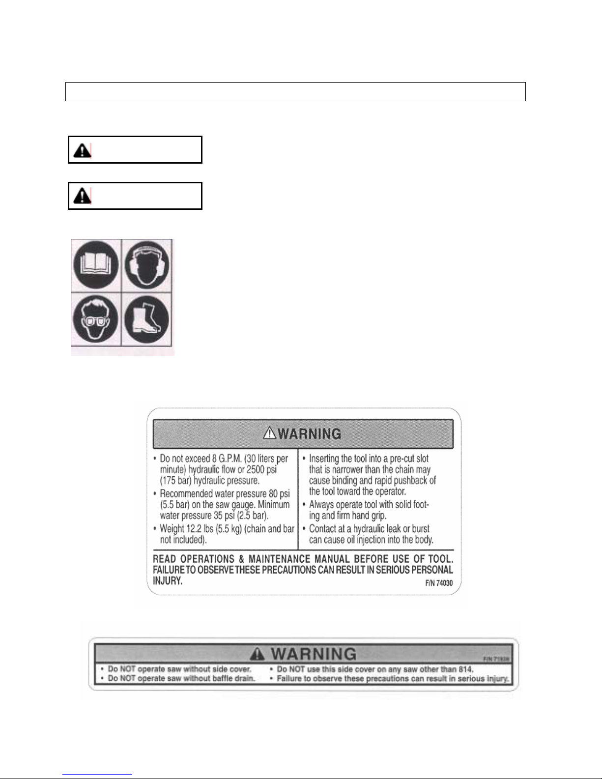
THE FOLLOWING SYMBOLS & LABELS MAY BE FOUND IN THIS MANUAL OR ON THE SAW
A potentially hazardous situation exists which, if not avoided, could
WARNING
CAUTION
Read the operator’s manual carefully and understand the contents
before you use this equipment.
Always use:
result in death or serious personal injury.
A potentially hazardous situation exists which, if not avoided, may
result in minor or moderate personal injury.
• Protective helmet
• Ear protection
• Protective glasses or full face protection
• Safety shoes
3
Page 4

814 OPERATOR’S MANUAL
SAFETY
THE FOLLOWING WARNING SYMBOL APPLIES TO ALL THE ITEMS LISTED ON THIS PAGE
A potentially hazardous situation exists which, if not avoided, could
WARNING
Note: Chain breakage can result in high-speed ejection of parts, which can result in death or
serious personal injury to operators or bystanders. The items listed immediately below are
critical to minimizing the risk of chain breakage and injury.
• DO NOT operate saw with a damaged, modified, or broken side cover or baffle drain. The side
cover and baffle drain provides protection against contact with moving parts, ejected debris,
broken chain, thrown water and concrete slurry.
• DO NOT exceed 8 gpm (30 lpm) hydraulic flow or 2500 psi (140 bar) hydraulic pressure.
• DO NOT install or run the chain backwards. The bumper should lead the segment into the cut.
• DO NOT run the saw motor backwards. The chain should travel away from the operator on the
top of the bar and return on the bottom of the bar.
• DO NOT insert the diamond chainsaw into a slot narrower than the chain segments. Rapid
pushback might occur. Ref: Most diamond segments are .225 inches wide (5.72 mm).
• DO NOT use the 814 side cover as a replacement side cover on any other saw.
• NEVER run a diamond chainsaw upside-down. Concrete debris can fly back into the
operator’s face.
• NEVER cut ductile iron pipe with the diamond chainsaw. Segment loss or chain breakage may
occur.
• DO NOT use your hands to search for hydraulic leaks. Hydraulic fluid escaping under
pressure can penetrate skin. If any hydraulic fluid is injected into skin seek medical attention
immediately.
result in death or serious personal injury.
Bumper
4
Page 5

814 OPERATOR’S MANUAL
SAFETY
THE FOLLOWING CAUTION SYMBOL APPLIES TO ALL ITEMS LISTED IMMEDIATELY BELOW
A potentially hazardous situation exists which, if not avoided, may
CAUTION
• Always turn the hydraulic power supply OFF when performing maintenance on the saw.
• SealPro™ diamond chains require a minimum water pressure of 20 psi (1.4 bar). Insufficient
water supply may result in excessive wear to the chain, which can lead to loss of strength and
chain breakage.
• Never start a diamond chaninsaw unless the bar, chain and side cover
are properly installed.
GENERAL SAFETY PRECAUTIONS
• Always wear protective clothes, including hard hat, eye protection, hearing protection, and gloves.
• Always operate tool with solid footing and handgrip.
• Slurry can be very slick. Remove or control to prevent yourself or others from slipping while cutting.
• Always work in a cleared area.
• Be sure there are no obstructions (plumbing, electrical conduit, air ducts) and no unnecessary people
present.
• Set up a well-marked safety zone with a roped boundary and clear signs.
• Breathing exhaust gasses is dangerous. Provide ventilation in closed areas.
• To avoid electrocution, check for live electrical wiring near cutting area.
result in minor or moderate personal injury.
5
Page 6

814 OPERATOR’S MANUAL
TECHNICAL SPECIFICATIONS
Weight without bar and chain
Length
Height
Width
Hydraulic Supply Requirements (maximum)
Hydraulic Fluid Requirements (type)
Water Pressure Requirements
Water Flow Requirements
Operating Speed
Noise Level
*For hydraulic systems with flow greater than 8 gpm (30 lpm) but less that 20 gpm (76 lpm) use ICS
flow adaptor, P/N 70350 to reduce flow to 8 gpm (30 lpm).
8 gpm (30 lpm) @ 2,500 psi (172.5 bar)
5,700 rpm (average free running)
4,900 sfm (average free running chain)
23 lbs (10.5 kg)
14.3 in (36.3 cm)
11.3 in (28.7 cm)
9.2 in (23.4 cm)
Mobil DTE13M or equivalent
Minimum: 20 psi (1.5 bar)
2 gpm(8 lpm) minimum
88dB @ 3 ft (1 m)
6
Page 7

814 OPERATOR’S MANUAL
BAR AND CHAIN INSTALLATION
STEP 1
Loosen side cover nuts and remove side
cover.
STEP 2
Place bar onto studs and chain adjustment
pin.
STEP 3
Turn chain-tensioning screw CCW until the
bar comes into contact with the drive
SET-UP
STEP 4
Mount the chain on the bar starting at the
drive sprocket & continue over the bar nose.
Install the chain correctly. The bumper must
always lead the segment into
the cut as shown here.
STEP 5
Make sure all the drive links are inside the bar
groove then pre-tension the chain.
7
Page 8

814 OPERATOR’S MANUAL
SET-UP
BAR AND CHAIN INSTALLATION
STEP 6
Install the side cover over the bar studs and
install side cover nuts. Finger tighten only.
STEP 8
Lift up on the nose of the bar and firmly
the side cover nuts.
See Note 2
Note 1: Do not “over tension” the chain. Loss of power will result. It is normal for the drivelinks to hang ½”
underneath the bar. The chain should be tight but be able to be pulled around the bar by hand.
Note 2: To prevent chain tensioner breakage, be sure the side cover nuts are tightened to approximately
20 ft-lbs (27 Nm)
tighten
STEP 7
Tension the chain. The chain should be tight
but able to be pulled around the bar by hand.
See Note 1
8
Page 9

814 OPERATOR’S MANUAL
OPERATION
PRE-CUT CHECKLIST
• Proper Chain Installation: The bumper should lead the segment into the cut.
• Proper Chain Tension: The chain should be tight but easily pulled around the bar by hand.
• Adequate Water Supply and Pressure:
Minimum Flow: 2 gpm (8 lpm)
Minimum Water Pressure: 20 psi (1.4 bar)
Note: The single most important factor an operator can control to increase chain life is to use
adequate water pressure. Insufficient water supply will result in excessive wear to the chain,
which can lead to loss of strength and chain breakage.
• Proper Hydraulic Supply to the Saw:
Maximum Flow: 8 gpm (30 lpm)
Maximum Hydraulic Pressure: 2,500 psi (172 bar)
• Proper Hydraulic Motor Rotation: Some power packs have reversible flow. Or the quick disconnects
may have been reversed on a previous job. The chain should travel away from the operator on the
top of the bar.
PLANNING THE CUT
• Select the proper chain for the material being cut.
• Outline the cut with a permanent marker for a visual cutting guide.
• Avoid pinching the bar and chain. Always cut the bottom of an opening first, then top, and then the
sides. Save the easiest cut for last.
• Be sure cut concrete cannot fall and injure operator or bystanders.
• Check for live electrical wiring near the cutting area or in the concrete to avoid electrocution which
can result in death or serious personal injury.
9
Page 10

814 OPERATOR’S MANUAL
OPERATION
CUTTING WITH THE 814
1. Plunge cut instead of starting at the top of the wall. This will reduce chatter, extend diamond life,
create a straighter cut and more quickly enable the use of the Wallwalker®.
2. Always operate a diamond chainsaw at full throttle. Apply enough feed force so that the free running
RPM drops 20 to 30%. If too much force is applied, the saw will lug or stall. The chain will not have
enough speed to cut effectively. If too little feed force is applied, the diamonds will skid and glaze
over.
3. For straight cuts use the “step cut” method. First score the entire cut line with the nose of the bar
approximately ½ inch (12mm) to 1 inch (25mm) deep. Next, deepen the cut by about 2 inches
(50 mm). This groove will help guide the bar for a straight cut. Then plunge all the way through and
complete the cut using the Wallwalker®.
4. Use the Wallwalker® to cut efficiently and reduce user fatigue. The Wallwalker® is a lever system
that converts inward force to downward force and will develop a 4-to-1 mechanical advantage. To
use correctly, plunge into the wall and simply engage the point of the Wallwalker® into the cut and
push straight in. The Wallwalker® will force the saw to feed down.
Apply an upward force on the trigger handle to keep the Wallwalker® engaged properly, otherwise
the Wallwalker® pick will skid, which will reduce the effectiveness. As the Wallwalke r begi ns to rotate
up, feed force is developed down the line of the intended cut. The feed force will increase as the
Wallwalker reaches the end of its stroke. When the Wallwalker bottoms out, p ull the saw out of the
cut a few inches and allow the Wallwalker to spring back into its starting position. Re-engage the pick
into the cut and repeat.
5. When cutting heavy rebar, slowly ”rock” the saw to help keep the diamonds exposed. Also, ex pect
less chain life when cutting heavy rebar.
6. Expect more chain stretch when making nose buried cuts for extended periods of time as the chain
does not have a chance to “sling” the slurry away from the nose of the bar.
7. If the saw begins to cut consistently crooked, turn the bar over and use the other side. Note: The
normal life of a guide bar is 2 to 3 chains. However, heavy rebar can shorten bar life too.
8. When using a new chain, you can increase the cutting speed by “opening up the diamonds”. Make a
few cuts in an abrasive material such as a cinder block.
10
Page 11

814 OPERATOR’S MANUAL
OPERATION
SYSTEM CLEAN-UP
1. Run saw, with water on, for 15 seconds out of cut to flush slurry and debris from chain, bar and drive
sprocket.
2. Wash concrete slurry from saw assembly. Flush out valve handle with high water pressure, spraying
water into all three openings.
3. Remove bar and chain. Flush out chain tensioner assembly location with high water pressure and
lube with grease.
4. Clean all hydraulic flush-face fittings on saw and power pack.
5. When done cleaning saw, spray entire saw body, chain, bar, drive sprocket, and hydraulic flush-face
fittings with a light weight penetrating oil. This will minimize rust and reduce slurry build up on saw
assembly.
11
Page 12

814 OPERATOR’S MANUAL
TROUBLESHOOTING
• SLOW CHAIN SPEED - Be sure the power pack is providing the correct hydraulic pressure and flow
8 gpm (30 lpm) and 2,500 psi (172 bar)
• POOR CUTTING PERFORMANCE - Diamonds may be “glazed over”. Make a few cut s in an
abrasive material such as a cinder block to expose the diamonds.
• PREMATURE CHAIN STRECH - Not enough water pressure. The minimum water pressure
required is 20 psi (1.4 bar). Insufficient water supply may result in excessive wear to the chain, which
can lead to loss of strength and chain breakage.
• CHAIN TENSIONER BREAKAGE - Side cover nuts are not tight enough.
• CHAIN IS RUNNING BACKWARDS - Hydraulics are hooked up backwards or power pack is set on
reverse flow mode
• WATER NOT FLOWING - Water hose is kinked or supply is not turned on.
12
Page 13
814 OPERATOR’S MANUAL
MAINTENANCE
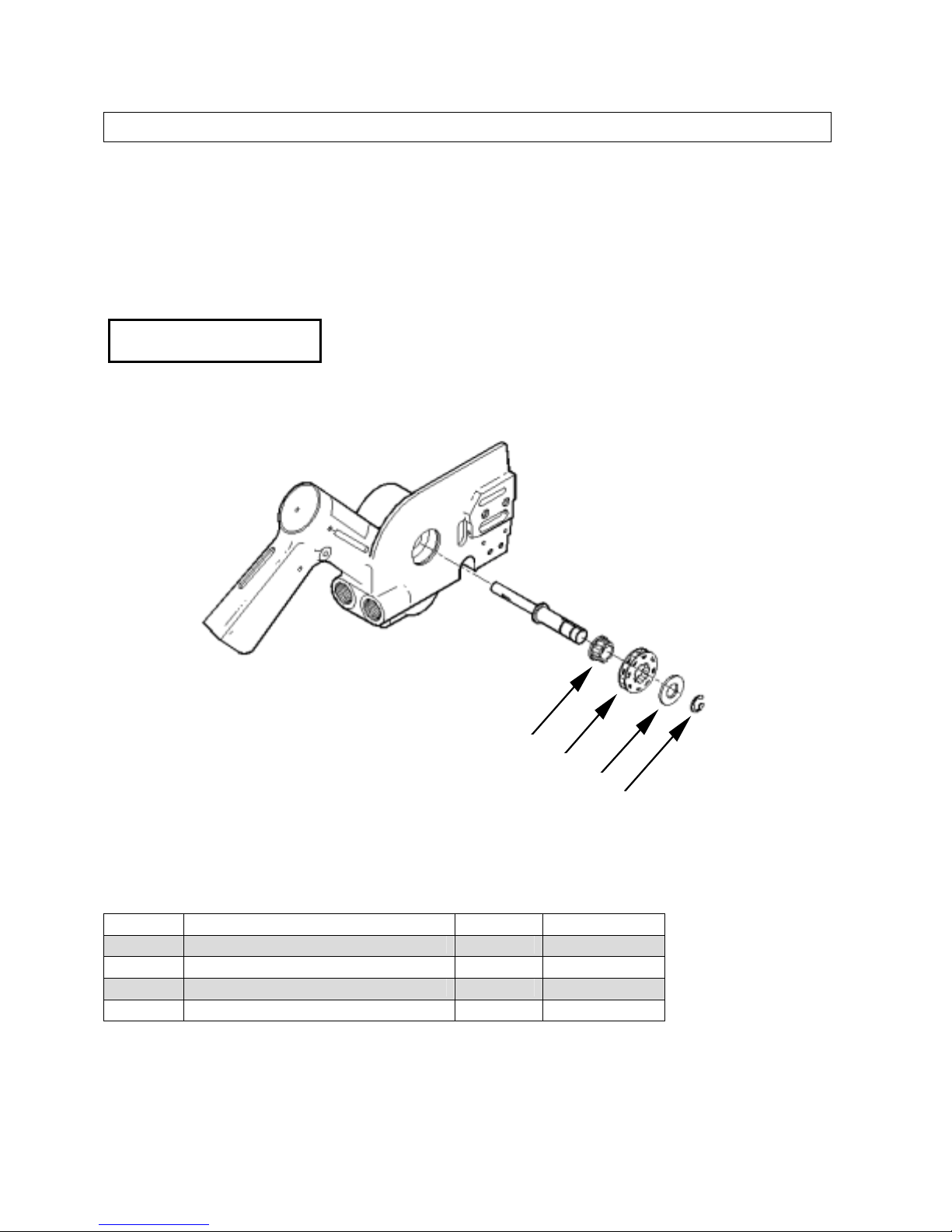
DRIVE SPROCKET REMOVAL AND INSTALLATION
1. Remove sidecover, bar and chain using scwrench.
2. Remove E-clip.
IMPORTANT
The drive sprocket (rim sprocket) is a wear item and should be
changed every 2-3 diamond chains
4
3
2
1
Key# Item Description Part # List Price
1 E-clip (12mm) 71387 $3.00
2 Tabbed Washer 71388 $6.00
3 Rim Sprocket (3/8-8t) 71385 $10.00
4 Splined Sprocket adaptor 71386 $25.00
* Pricing and Specifications subject to change without notice.
Note: Rim sprocket may be installed with either side facing outwards.
13
Page 14

814 OPERATOR’S MANUAL
REFERENCE
APPROXIMATE CUTTING RATES
Material Cutting Rate
6 in (15cm) concrete 5 lineal inches per minute (12cm/min)
6 in (15cm) red brick 10 lineal inches per minute (25cm/min)
#4 (12mm) rebar 10-20 seconds through each piece
INCH-FOOT DEFINITION
An in-ft is a measure of how much material is to be cut.
An in-ft is defined as: depth in inches times length in feet.
Example: How many in-ft are in this doorway?
1. Determine the depth of the cut in inches.
For this example, 8 inches.
2. Determine the length of the cut in feet.
3+7+3+7=20 feet
3. Multiply the two numbers
8 in x 20 ft = 160 in-ft
1sq-m = 129 in-ft
14
Page 15
814 OPERATOR’S MANUAL
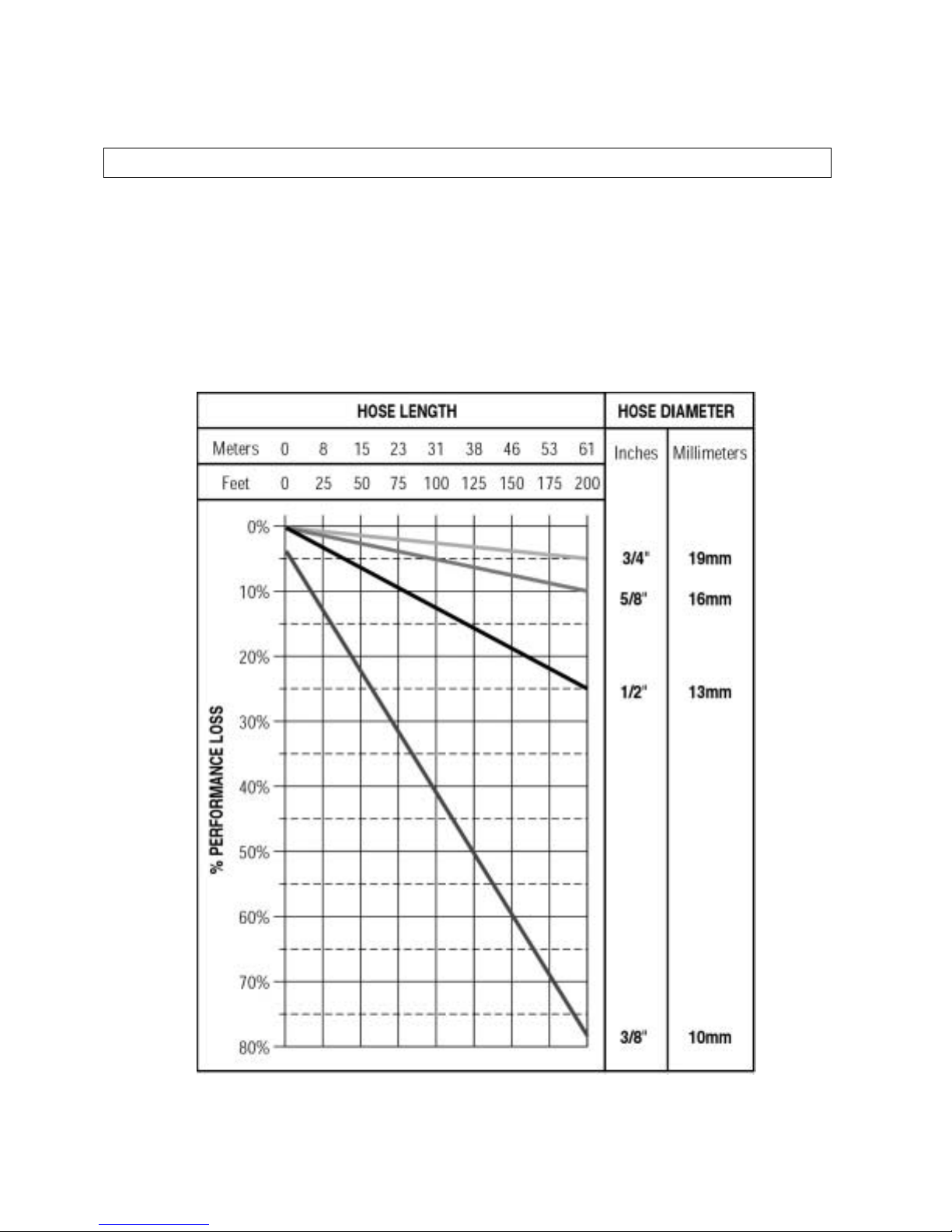
REFERENCE
PERFORMANCE LOSS VS HYDRAULIC HOSE LENGTH
ASSUMPTIONS:
• 8 gpm (30 lpm) flow and 2,500 psi (172 bar)
• Zero elevation change
• 2 pairs of flush-face fittings per hose
15
 Loading...