

Page 1
Cable Free USB 2.0 Hub
User Guide
Powered by ExtremeUSB® Technology
Page 2

Thank you for purchasing the WiRanger. Please read this guide thoroughly
before installation.
This document applies to Part Numbers: 00-00228 through 00-00230.
FCC Radio Frequency Interference Statement Warning
The WiRanger has been tested and found to comply with the limits for a
Class B digital device, pursuant to part 15 of the FCC Rules. These limits are
designed to provide reasonable protection against harmful interference in a
residential installation. The WiRanger generates, uses and can radiate radio
frequency energy and, if not installed and used in accordance with the
instructions, may cause harmful interference to radio communications.
However, there is no guarantee that interference will not occur in a particular
installation. If the WiRanger does cause harmful interference to radio or
television reception, which can be determined by turning the equipment off
and on, the user is encouraged to try to correct the interference by one or
more of the following measures:
• Reorient or relocate the receiving antenna.
• Increase the separation between the equipment and
receiver.
• Connect the equipment into an outlet on a circuit different
from that to which the receiver is connected.
• Consult the dealer or an experienced radio/ TV technician
for help.
FCC Radiation Exposure Statement:
This equipment complies with FCC radiation exposure limits set forth for an
uncontrolled environment. This equipment should be installed and operated
with a minimum distance of 20cm between the radiator and your body.
CE Statement
Icron Technologies Corporation declares that the WiRanger conforms to the
specifications listed below, following the provisions of the European
R&TTE directive 1999/5/EC:
Icron Technologies Corporation vakuuttaa täten että dieses produkt
tyyppinen laite on direktiivin 1999/5/EY oleellisten vaatimusten ja sitä
koskevien näiden direktiivien muiden ehtojen mukainen.
Page 3

Cable Free USB 2.0 Hub
Icron Technologies Corporation déclare que le produit est conforme aux
conditions essentielles et aux dispositions relatives à la directive 1999/5/EC.
• EN 301 489-1, 301 489-17 General EMC requirements for
Radio equipment.
• EN 609 50 Safety
• EN 300-328 Technical requirements for Radio equipment.
Caution: This equipment is intended to be used in all EU and EFTA
countries. Outdoor use may be restricted to certain frequencies and/or may
require a license for operation. Contact local Authority for procedure to
follow.
Note: Combinations of power levels and antennas resulting in a radiated
power level of above 100 mW equivalent isotropic radiated power (EIRP)
are considered as not compliant with the above mentioned directive and are
not allowed for use within the European community and countries that have
adopted the European R&TTE directive 1999/5/EC.
For more details on legal combinations of power levels and antennas, contact
Icron Technologies Corporation.
Belgique:
Dans le cas d'une utilisation privée, à l'extérieur d'un bâtiment, au-dessus
d'un espace public, aucun enregistrement n'est nécessaire pour une distance
de moins de 300m. Pour une distance supérieure à 300m un enregistrement
auprès de l'IBPT est requise. Pour une utilisation publique à l'extérieur de
bâtiments, une licence de l'IBPT est requise. Pour les enregistrements et
licences, veuillez contacter l'IBPT.
France:
2.4 GHz Bande : les canaux 10, 11 (2457 et 2462 MHz respectivement) sont
complétement libres d'utilisation en France (en utilisation intérieur). Pour ce
qui est des autres canaux, ils peuvent être soumis à autorisation selon le
départment. L'utilisation en extérieur est soumis à autorisation préalable et
très restreint. Vous pouvez contacter l'Autorité de Régulation des
Télécommunications (http://www.art-telecom.fr) pour de plus amples
renseignements.
SAFETY NOTICES
Caution: Do not use this product near water, for example, in a wet basement
or near a swimming pool.
Avoid using this product during an electrical storm. There may be a remote
risk of electric shock from lightning.
Page 4

IC Statement
This Class B digital apparatus complies with Canadian ICES-003 and
RSS210 rules.
Cet appareil numérique de la classe B est conforme à la norme NMB-003 et
CNR210 du Canada.
The use of this device in a system operating either partially or completely
outdoors may require the user to obtain a license for the system according to
the Canadian regulations.
To reduce potential radio interference to other users, the antenna type and its
gain should be so chosen that the equivalent isotropically radiated power
(e.i.r.p.) is not more than that permitted for successful communication.
This device has been designed to operate with the antennas listed below, and
having a maximum gain of 2.0 dBi @ 2.4GHz. Antennas not included in this
list or having a gain greater than 2.0 dBi @ 2.4GHz are strictly prohibited
for use with this device. The required antenna impedance is 50 Ohms.
The antennae supplied with this product is manufactured by Wellshow
Technology Co. Ltd., Model # WSTS-AW24RSMA-001.
©2007 Icron Technologies Corporation. All rights reserved. Icron
Technologies Corporation, the Icron Technologies Corporation logo, and the
Icron Technologies Corporation products referred to herein are either the
trademarks or the registered trademarks of Icron Technologies Corporation.
All other trademarks are property of their respective owners. Icron
Technologies Corporation assumes no responsibility for errors that may
appear in this manual. Information contained herein is subject to change
without notice.
Page 5

User Guide
Contents
Introduction................................................................................................ 1
WiRanger Product Contents....................................................................... 1
About the WiRanger .................................................................................. 2
Before You Begin ...................................................................................... 7
Installing the LEX unit............................................................................... 7
Installing the REX unit............................................................................... 7
Establishing Wireless Communication ...................................................... 7
Checking the Installation............................................................................ 8
Connecting a USB Device ......................................................................... 8
Advanced Setup – Viewing and Changing the 802.11g Radio Channel .... 9
Advanced Setup – Pairing a LEX unit and a REX unit............................ 12
Troubleshooting ....................................................................................... 14
Specifications ........................................................................................... 18
Limited Hardware Warranty .................................................................... 19
Hardware Remedies ................................................................................. 19
Limitation of Liability.............................................................................. 19
Obtaining Warranty Service..................................................................... 20
Contacting Technical Support .................................................................. 20
i
Page 6

Notes
ii
Page 7

User Guide
Introduction
This manual is intended to assist IT professionals install the WiRanger –
Cable Free USB 2.0 Hub. The instructions in this guide assume a general
knowledge of computer installation procedures, wireless network installation
requirements, and some understanding of USB devices.
NOTE: Notes give additional information that could make
installation easier.
WiRanger Product Contents
When you open your WiRanger for the first time you should find the
following items:
• WiRanger User Guide
• Local EXtender unit or LEX unit (includes antenna)
• Remote EXtender unit or REX unit (includes antenna)
• AC power adapter (2)
• USB cable (2m long)
To complete the installation, you will also require the following items that
are not included with the product:
• USB 1.1 or 2.0 compatible computer
• USB device(s)
NOTE: The WiRanger uses an IEEE 802.11g radio platform to
wirelessly communicate between the LEX unit and the REX
unit using the 2.4GHz radio frequency range. Other
products, such as wireless routers and 2.4GHz cordless
telephones, also broadcast in this same 2.4GHz range. Please
be aware of potential interference issues with such products
before you begin installation of the WiRanger.
NOTE: The LEX unit and the REX unit of your new WiRanger have
been “Paired” during manufacturing. This means that they
will only communciate with each other, even if other
WiRanger units are installed near by.
NOTE: Use only the AC adapters supplied with the WiRanger. Use
of substitute adapters may cause permanent damage to the
system and will void the warranty.
1
Page 8
About the WiRanger
The WiRanger is the world’s first wireless USB 2.0 Hub, combining Icron’s
patented ExtremeUSB® technology and an industry standard IEEE 802.11g
radio. The WiRanger Hub enables wireless connection of USB devices up to
30 meters from the host computer.
The WiRanger installs as a Generic USB Hub and requires no additional
drivers to be installed. It is composed of two individual units, the LEX unit,
which connects to the host computer, and the REX unit, which connects to
the remote USB device(s).
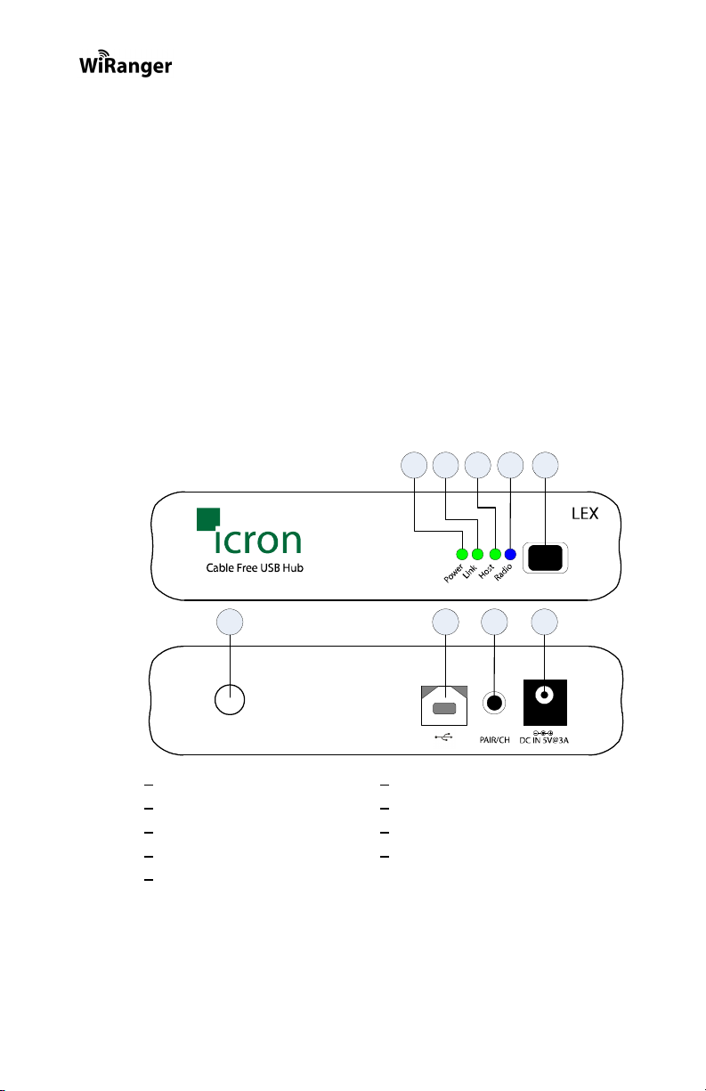
The LEX unit
The LEX unit connects to the host computer using a conventional USB
cable. It also connects to a power outlet through an AC power adapter.
1 2 3 54
Front
View
6 7 8 9
Rear
View
* IR port used to pair the LEX unit and the REX unit only
** Pair/CH button is for advanced users only. See Pages 9 and 12 for advanced instructions.
1 Power LED
2 Link LED
3 Host LED
4 Radio Activity LED
5 Infra Red (IR) Port*
6 Antenna connector
7 Host port (USB Type-B)
8 Pair/Channel Change Button**
9 Power connector (5V @ 3A)
2
Page 9
User Guide
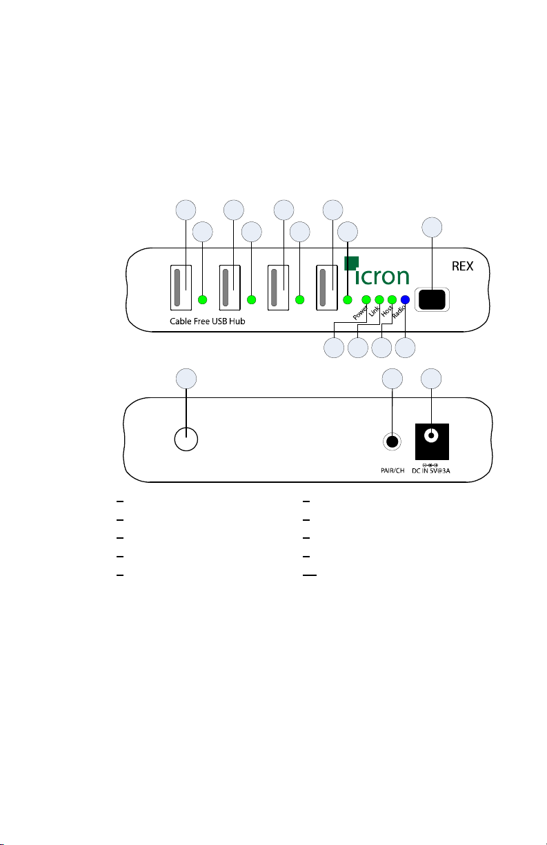
The REX unit
The REX unit allows you to connect up to four USB devices directly;
additional devices may be connected by attaching a conventional USB
hub to one of the device ports. The REX unit also connects to a power
outlet through an AC power adapter.
1 1 1 1
2 2 2 2
Front
View
7
6543
8 9 10
Rear
View
1 Device ports (USB Type-A)
2 Device LED’s
3 Power LED
4 Link LED
5 Host LED
* IR port used to pair the LEX unit and the REX unit only
** Pair/CH button is for advanced users only. See Pages 9 and 12 for advanced instructions.
6 Radio Activity LED
7 Infra Red (IR) Port*
8 Antenna connector
9 Pair/Channel Change Button**
10 Power connector
3
Page 10

WiRanger LED Descriptions
The WiRanger uses LED’s to indicate status to the user. LED operation
is the same for the LEX unit and the REX unit.
LED Name Description
Power LED Indicates 5V power is connected to the unit.
Link LED Indicates communications have been established
between the LEX unit and the REX unit.
Independent of USB communication.
Host LED Indicates successful communications between the
host PC and the USB 2.0 hub in the REX unit.
Radio LED Indicates active wireless data transmission and/or
reception.
Device LED’s
(REX unit only)
GREEN: Indicates that the attached USB device is
correctly detected by the host PC.
ORANGE: Indicates that the attached USB device
has drawn too much current and hence the hub
has shut this Device port off to protect the
WiRanger. Disconnect and reconnect the REX
unit’s power to clear this fault condition.
4
Page 11

User Guide
Wireless Operation
The LEX unit and REX unit wirelessly communicate over the IEEE
802.11g radio protocol at a distance up to 30 meters. The actual
communications distance will vary greatly depending on the amount and
type of physical obstacles and radio interference in your area. In
general, the WiRanger should have similar range to that of a normal
802.11g router or access point.
The LEX unit and REX unit of this WiRanger are “Paired” at the factory
so that they will only communicate with each other, even if other
WiRanger’s are installed near by.
NOTE: Under normal operating conditions, you should never need to
“Pair” the units. However, if absolutely required, the units
can be “Paired” using the procedure listed on Page 12,
Advanced Setup – Pairing a LEX unit and a REX unit.
The IEEE 802.11g standard allows for wireless devices to operate on
one of 11 different Radio Channels. This means that your 802.11g
wireless router or access point can co-exist with the WiRanger, if they
are configured to operate on an approprirately chosen channel.
5
Page 12

USB Type A
USB Type A
USB Type B
USB Type B
Your WiRanger will be pre-configured to operate on 802.11g Radio
Channel 11. Ideally, your other 802.11g products should be configured
to work on a channel that is at least 5 channels apart from the one used
by the WiRanger.
For example, if the WiRanger is on channel 11 and you also have a
802.11b/g router. Then configure the router to operate on channel 6, or
lower.
NOTE: If required, you can view or changed the current WiRanger
802.11g Radio Channel. See Advanced Setup – Viewing and
Changing the 802.11g Radio Channel on Page 9 for
instructions.
NOTE: The WiRanger does not broadcast an SSID and will not be
visible to a wireless network scan.
USB Cables
USB cables have two distinct connectors. The Type A connector is used
to connect the cable from a USB device to the Type A port on a
computer or hub. The Type B connector is used to attach the USB cable
to a USB device.
port
connector
port
connector
Compatibility
The WiRanger complies with USB 2.0 specifications governing the
design of high-speed USB devices. However, Icron Technologies
Corporation does not guarantee that all USB devices are compatible
with the WiRanger.
6
Page 13

User Guide
Before You Begin
Before you can install the WiRanger, you need to prepare your site.
1. Determine where the host computer is to be located and set up the
computer.
2. Determine where you want to locate the USB device(s).
3. Determine suitable locations for the LEX unit and the REX unit
such that they will be able to maintain wireless communication.
Physical obstacles and other radio wave emitting devices can cause
interference that will reduce the maximum distance and data rate
between the LEX unit and the REX unit.
4. If other 802.11g based products will be in operation in the same
area, determine the optimal Radio Channel selection for all wireless
products. See the Wireless Operation section on Page 5 for more
information on channel selection.
Installing the LEX unit
1. Place the LEX unit near the host computer.
2. Plug the power adapter into a suitable AC outlet.
3. Connect the power adapter to the LEX unit.
4. Plug the Type-B connector on the USB cable (included) into the
Host port on the LEX unit.
5. Plug the Type-A connector on the USB cable into the USB port on
the computer.
Installing the REX unit
1. Place the REX unit near the USB device(s).
2. Plug the power adapter into a suitable AC outlet.
3. Connect the power adapter to the REX unit.
Establishing Wireless Communication
The WiRanger will automatically establish a wireless connection between
the LEX unit and the REX unit once power is applied to both units and they
are located within their operating range. The Link LED on both units will
turn on once the wireless connection has been made.
NOTE: Please be aware that it may take up to 30 seconds for the
WiRanger to establish wireless communication.
7
Page 14

Checking the Installation
1. Check that the Power LED’s on the LEX unit and REX unit are
both on.
2. Check that the Link LED’s on the LEX unit and REX unit are both
on.
3. Check that the Host LED’s on the LEX unit and REX unit are both
on.
NOTE: The Radio Activity LED will only flash when the 802.11g
radio link is actively transmitting or receiving data.
4. For Windows users (2000, XP, or Vista) open Device Manager to
confirm that the WiRanger has installed correctly. Expand the entry
for Universal Serial Bus controllers by clicking the + sign. If the
WiRanger has been installed correctly you should find it listed as a
Generic USB Hub.
NOTE: To open Device Manager in Windows 2000 or XP: Right-
click My Computer then select Properties, select the
Hardware tab and click the Device Manager button
NOTE: To open Device Manager in Windows Vista: Open the Start
menu, right-click on Computer, select Manage and finally
click on "Device Manager" in the left-hand tree
5. For Mac OS X users open the System Profiler to confirm that the
WiRanger has installed correctly. In the left hand column under
Hardware, select “USB” and inspect the right hand panel. If the
WiRanger has been installed correctly you should find it listed as a
Hub under the USB High-Speed Bus.
NOTE: To open System Profiler in OS X: Open the Finder, select
Applications, then open the Utilities folder and double click
on the System Profiler icon.
Connecting a USB Device
1. Install any software required to operate the USB device(s). Refer to
the documentation for the device(s), as required.
2. Connect the USB device(s) to the Device port(s) on the REX unit.
3. Check that the Device LED on the REX unit is on.
4. Confirm on the host PC that the each connected device operates as
expected.
8
Page 15

User Guide
Advanced Setup – Viewing and Changing the 802.11g
Radio Channel
The following instructions are for advanced users only.
These instructions should only be executed if specifically required and if you
are comfortable with the operations. Under normal operating conditions,
you should not need to view or change the 802.11g Radio Channel.
Viewing the Current 802.11g Radio Channel
NOTE: Radio Channel viewing can be done on either the LEX unit
or the REX unit. The procedure is the same.
NOTE: Viewing the current 802.11g Radio Channel will not disrupt
normal USB communication between the LEX unit and the
REX unit.
1. Power on either the LEX unit or the REX unit and wait for
approximately 20 seconds before proceeding to step 2. If the unit is
already on, proceed to step 2.
2. On the selected LEX unit or REX unit, press and hold (do not
release) the Pair/CH button for a minimum of 10 seconds. The
button can be released when the Host, Link and Radio LED’s start
to blink rapidly.
3. Upon release of the Pair/CH button the current 802.11g Radio
Channel will be displayed as a pattern on the Host, Link, and Radio
LED’s. Please see the figure below for the description of the LED
Radio Channel patterns.
4. DO NOT press the Pair/CH button again. After 60 seconds the
selected LEX unit or REX unit LED’s will return to their normal
operation.
NOTE: If the button is pressed again and a Channel Change is not
desired, DO NOT press the button again. After 60 seconds
from last button press the selected LEX unit or REX unit
LED’s will return to their normal operation and no change in
the unit’s channel selection will be made.
9
Page 16

NOTE: If power is removed from the unit while the Channel LED
Pattern is still active, no change in the units channel selection
will be made.
Changing the 802.11g Radio Channel
NOTE: 802.11g radios have 11 user-selectable “Channels”. Each
radio channel broadcasts data in a different frequency band
within the 2.4GHz range. By selecting a different Radio
Channel, you can try to find a channel with minimal radio
interference. This can improve signal quality and data rates.
NOTE: When changing the Radio Channel for a “Paired” system, the
channel change MUST BE completed on BOTH the LEX
unit and the REX unit. The order is non-specific.
NOTE: STOP all devices connected to the REX unit prior to
changing the channel on either unit. Changing the Radio
Channel will disrupt USB traffic.
1. Power on either the LEX unit or the REX unit and wait for
approximately 20 seconds before proceeding to step 2. If the unit is
already on, proceed to step 2.
2. On the selected LEX unit or REX unit, press and hold (do not
release) the Pair/CH button for a minimum of 10 seconds. The
button can be released when the Host, Link and Radio LED’s start
to blink rapidly.
3. Upon release of the Pair/CH button. The current 802.11g Radio
Channel will be displayed by as a pattern on the Host, Link, and
Radio LED’s. Please see the figure below for the description of the
LED Radio Channel patterns.
4. To change the channel press and release the Pair/CH button until
the desired channel pattern as seen in the above figure is visible on
the LED’s. Upon reaching channel 11 the pattern will return to
channel 1.
NOTE: If the Pair/CH button is not pressed for 60 seconds the LED’s
will return to their normal operation and no changes will be
made to the current channel selection.
10
Page 17

User Guide
NOTE: If wireless communication is present it will continue until a
channel change is confirmed.
5. Once the desired 802.11g Radio Channel is displayed, press and
hold the Pair/CH button for 10 seconds. The button can be released
when the Host, Link and Radio LED’s start to blink rapidly.
NOTE: If the LED’s do not start blinking rapidly within 20 seconds
release the button and confirm that the LED pattern still
shows your desired channel pattern. If it does, repeat step 5.
If it does not, return to step 4.
6. Upon release of the Pair/CH button the LED’s will continue to blink
for approximately 20 seconds while the Channel Change is stored
and the 802.11g radio reboots. Once the blinking stops the Channel
Change is complete.
NOTE: DO NOT remove power while LED’s are blinking.
NOTE: If the channel selection on the LEX unit and the REX unit
are no longer the same the USB traffic will now stop. If the
channel selection on the LEX and REX are made the same
the USB traffic will begin.
7. If only one side of the system has been changed repeat steps 1 to 6
for the other side of the system. If channel selection is complete on
both sides of the system go to step 8.
8. Connect a USB cable between the WiRanger and the host PC, and
confirm its operation by checking if it is listed in Device Manager
(for Windows installations), or System Profiler (for Mac OS X
installations) under Universal Serial Bus controllers as a “Generic
USB Hub”.
11
Page 18

Advanced Setup – Pairing a LEX unit and a REX unit
The following instructions are for advanced users only.
These instructions should only be executed if specifically required and if you
are comfortable with the operations. Under normal operating conditions,
you should never need to pair a LEX unit and a REX unit.
Paired units are defined as a LEX unit and a REX unit that are aware of each
other’s unique address and communicate exclusively.
Pairing is accomplished by infrared (IR) communication through the IR
windows on the LEX unit and the REX unit; pairing information is not sent
over the 802.11g radios. The IR communication distance is limited to an
approximate distance of 20 cm.
NOTE: The WiRanger’s LEX unit and REX unit are shipped paired
from the factory.
NOTE: If the Pair/CH button is pressed whether accidentally or
purposefully and the LEX unit and the REX unit are not able
to communicate via the IR interface no effect in operation
will be detected and pairing will not occur.
1. Place the LEX unit and the REX unit 5 cm apart from each other
with their IR windows pointed directly at each other. The IR
windows must have a clear and unobstructed view of each other.
2. Power on both the LEX unit and the REX unit and wait for
approximately 20 seconds before proceeding to step 3. If the units
are already on, proceed to step 3.
3. Press the Pair/CH button on either unit for approximately 1 second.
Upon release of the button the Host, Link and Radio LED’s on both
the LEX unit and the REX unit should begin to blink rapidly.
NOTE: DO NOT remove power while LED’s are blinking.
NOTE: If step 3 is attempted too early after power up, the pairing
procedure will not occur. Wait a few seconds longer and
retry step 3.
NOTE: If the rapid blinking of the LED’s does not occur, confirm
that the IR windows on the LEX unit and the REX unit are
unobstructed, pointed at each other, and are 5 cm apart.
Retry pressing the PAIR button. If the LED’s still do not
blink upon release of the button unplug both units for at least
10 seconds and return to step 1.
12
Page 19

User Guide
4. Wait for the LED’s on the LEX unit and the REX unit to stop
blinking and for the Link LED to turn on.
NOTE: If the Link LED does not turn on within 30 seconds return to
step 1.
5. The LEX unit and the REX unit are now Paired and are free to be
unplugged and moved to their desired locations.
6. Once the units are installed in their specific locations, connect a
USB cable between the WiRanger and the host PC to confirm the
WiRanger’s operation. If the system has been installed and paired
correctly it should be listed in Device Manager (for Windows
installations), or System Profiler (for Mac OS X installations) under
Universal Serial Bus controllers as a “Generic USB Hub”.
13
Page 20

Troubleshooting
The following table provides troubleshooting help. The topics are arranged
in the order in which they should be executed in most situations. If you are
unable to resolve the problem after following these instructions, please
contact technical support for further assistance (see page 20).
Symptoms/Cause
All LEDs on LEX unit
and REX unit are off.
Cause:
The WiRanger is not
receiving power from
the adapter
Remedy
1. Ensure that the power adapters are connected
to both the LEX unit and the REX unit
2. Check that the adapters are connected to a
live source of electrical power
14
Page 21

User Guide
Symptoms/Cause
Link LEDs on LEX unit
and REX unit are off.
Cause:
There is no wireless
connection between the
LEX unit and the REX
unit because:
a) The units are too far
apart.
b) There is too much
Radio Interference.
c) The WiRanger is
not configured
correctly.
d) The WiRanger is
malfunctioning.
Remedy
Move the LEX unit and REX unit together so that
they are about 1 meter apart (3’) and power both
units. Confirm that they can establish a radio link.
If the WiRanger can establish wireless
communications at short range:
1. The original LEX unit and REX unit placement
is too far apart. Move the units to physically
closer positions that have fewer obstacles in
the way (walls, ceilings, etc).
2. And/or, there is excessive Radio Interference
on the 802.11g Radio Channel.
3. Using standard Wireless Networking software,
confirm if there are any other 802.11g radio
networks operating on or near the same
channel as the WiRanger. (Note you can
determine the current WiRanger Radio
Channel using the procedure on Page 9.)
4. Configure all conflicting 802.11g products so
that they use evenly separated Radio
Channels. Optimal separation is five
channels, so channels 1, 6, and 11 will
provide the least interference between
themselves.
If the WiRanger cannot establish wireless
communications at short range:
1. Confirm that the Radio Antennas are properly
secured to the antenna connectors of the
WiRanger.
2. Confirm the Radio Channels of the LEX unit
and the REX unit as described on Page 9.
3. If the LEX unit and the REX unit are not
configured with the same Radio Channels,
then set both units to the same channel as
described on Page 10.
4. If both units are already configured to the
same Radio Channel, then attempt the Pairing
Procedure described on Page 12.
5. If the above procedures cannot establish
wireless communications, then contact
Technical Support for further assistance (see
page 20).
15
Page 22

Symptoms/Cause
Link LED on LEX unit is
on;
Host LED on LEX unit
is off.
Cause:
a) The computer is not
functioning.
b) The LEX unit is not
connected to the
computer.
c) There is too much
Radio Interference
for USB
communication to
succeed.
d) The WiRanger is
malfunctioning.
A device is connected
to REX unit and the
corresponding Device
LED is off
Cause:
a) The USB device is
malfunctioning.
b) The computer does
not recognise the
USB device.
c) The application
software for the
device is not
operating.
d) The WiRanger is
malfunctioning.
Remedy
1. Disconnect all USB devices from the REX
unit.
2. Disconnect the LEX unit from the computer.
3. Disconnect and then reconnect the power
adapters to the WiRanger.
4. Reconnect the LEX unit to the computer.
5. In the Universal Serial Bus controllers section
of Device Manager, check that the WiRanger
is recognised as a “Generic USB Hub”.
6. If the problem persists, move the LEX unit and
REX unit together so that they are about 1
meter apart (3’) and power both units and
connect the LEX unit to the host PC.
7. Confirm that the WiRanger can establish a
radio link and that the Host LED’s turn on.
8. If the WiRanger is still not recognised, contact
Technical Support for assistance (see page
20).
1. Disconnect the WiRanger from the computer.
2. Connect the USB device directly to the USB
port on the computer.
3. If the device does not operate properly,
consult the user documentation for the device.
4. If the device operates properly when directly
connected to the computer, connect another
device (of a different type) to the WiRanger.
Connect the WiRanger to the computer.
5. If the second device does not operate, the
WiRanger may be malfunctioning. Contact
Technical Support for assistance (see page
20).
6. If the second device does operate properly,
the first device may not be compatible with the
WiRanger. Contact Technical Support for
assistance (see page 20).
16
Page 23

User Guide
Symptoms/Cause
All LEDs on both the
LEX unit and REX unit
are on but the device
does not operate
correctly
Cause:
a) The USB device is
malfunctioning.
b) The computer does
not recognise the
USB device.
c) The application
software for the
device is not
operating.
d) The WiRanger is
malfunctioning.
Remedy
1. Disconnect the WiRanger from the computer.
2. Connect the USB device directly to the USB
port on the computer.
3. If the device does not operate properly,
consult the user documentation for the device.
4. If the device operates properly when directly
connected to the computer, connect another
device (of a different type) to the WiRanger.
Connect the WiRanger to the computer.
5. If the second device does not operate, the
WiRanger may be malfunctioning. Contact
Technical Support for assistance (see page
20).
6. If the second device does operate properly,
the first device may not be compatible with the
WiRanger. Contact Technical Support for
assistance (see page 20).
17
Page 24

Specifications
Radio Max Data Rate* 54Mbps (802.11g)
USB device support High-speed devices (480 Mb/s)
Full speed devices (12 Mb/s)
Low speed devices (1.5 Mb/s)
USB host support USB 1.1: UHCI & OHCI
USB 2.0: EHCI
Upstream USB hub
support
Downstream USB hub
support
Maximum Devices
Connected
Security Standard 64 bit WEP security enabled by Radio
AC adapter(s)
NOTE: Use only the
AC adapters provided
with the WiRanger.
Power available to USB
device at REX unit
USB cable 2 meters (6.6 ft)
LEX unit connector
(upstream)
REX unit connector
(downstream)
LEX unit dimensions 110mm x 69mm x 28mm (4.33” x 2.72” x 1.10”)
LEX unit weight TBD
REX unit dimensions 110mm x 69mm x 28mm (4.33” x 2.72” x 1.10”)
Yes
Yes
14 including USB hubs
Input (International): 110/240 V AC, 50 – 60 Hz
Output (International): 5 V DC, 3 A
Input (NA-only): 110 V AC, 60 Hz
Output (NA-only): 5 V DC, 3 A
4 x 500 mA
1 x USB Type B
4 x USB Type A
REX unit weight TBD
System shipping weight TBD
Temperature range 4°C to 40°C
Regulatory testing FCC, CE Class B
*actual performance will vary depending on operating environment
18
Page 25

User Guide
Limited Hardware Warranty
Icron Technologies Corporation warrants that any hardware products
accompanying this documentation shall be free from significant defects in
material and workmanship for a period of one year from the date of
purchase. Icron Technologies Corporation’s hardware warranty extends to
Licensee, its customers and end users.
Hardware Remedies
Icron Technologies Corporation’s entire liability and the Licensee’s
exclusive remedy for any breach of warranty, shall be, at Icron Technologies
Corporation’s option, either (a) return of the price paid or (b) repair or
replacement of hardware, which will be warranted for the remainder of the
original warranty period or 30 days, whichever is longer. These remedies are
void if failure of the hardware has resulted from accident, abuse, or
misapplication.
Limitation of Liability
The hardware warranty set forth in this agreement replaces all other
warranties. Icron Technologies Corporation expressly disclaims all other
merchantability and fitness for a particular purpose and non-infringement of
third-party rights with respect to the hardware. Icron Technologies
Corporation dealer, agent, or employee is authorized to make any
modification, extension, or addition to this warranty. Under no
circumstances will Icron Technologies Corporation, its suppliers or licensors
be liable for any costs of procurement or substitute products or services, lost
profits, loss of information or data, or any other special, indirect,
consequential, or incidental damages arising in any way out of the sale of,
use of, or inability to use Icron Technologies Corporation product or service,
even if Icron Technologies Corporation, its suppliers or licensors have been
advised of the possibility of such damages. In no case shall Icron
Technologies Corporation, its suppliers and licensors’ liability exceed the
actual money paid for the products at issue. Because some jurisdictions do
not allow the limitation of implied warranties of liability for incidental,
consequential, special, or indirect damages, the above limitation may not
always apply. The above limitations will not apply in case of personal injury
where and to the extent that applicable law requires such liability.
19
Page 26

Obtaining Warranty Service
To obtain warranty service, you must contact Icron Technologies
Corporation within the warranty period for a Return Material Authorization
(RMA) number. Be sure you have the serial numbers of the LEX unit and
REX unit units before calling. Package the product appropriately for safe
shipment and mark the RMA number on the outside of the package. The
package must be sent prepaid to Icron Technologies Corporation. We
recommend that you insure it or send it by a method that provides for
tracking of the package. The repaired or replaced item will be shipped to
you, at Icron Technologies Corporation’s expense, not later than thirty days
after Icron Technologies Corporation receives the defective product.
Address the returned product to:
RMA Coordinator
Icron Technologies Corporation
4664 Lougheed Highway, Suite 221
Burnaby, BC, V5C 5T5
Canada
Tel: 604-638-3920
Contacting Technical Support
If you require technical assistance, send an e-mail message to:
techsupport@icron.com
To help us serve you better, please include the following information with
your technical support request:
• Description of the problem
• Host computer make and model
• Type of operating system installed (e.g. Windows XP, Mac OS X,
etc.)
• Part number and serial number of the LEX unit and the REX unit
• Make and model of any USB device attached to the WiRanger
• Description of the installation
20
Page 27

Icron Technologies Corporation
4664 Lougheed Highway, Suite 221
Burnaby, BC, V5C 5T5
Canada
Tel: 604-638-3920
Fax: 604-638-3930
www.icron.com
90-00335
 Loading...