

Page 1
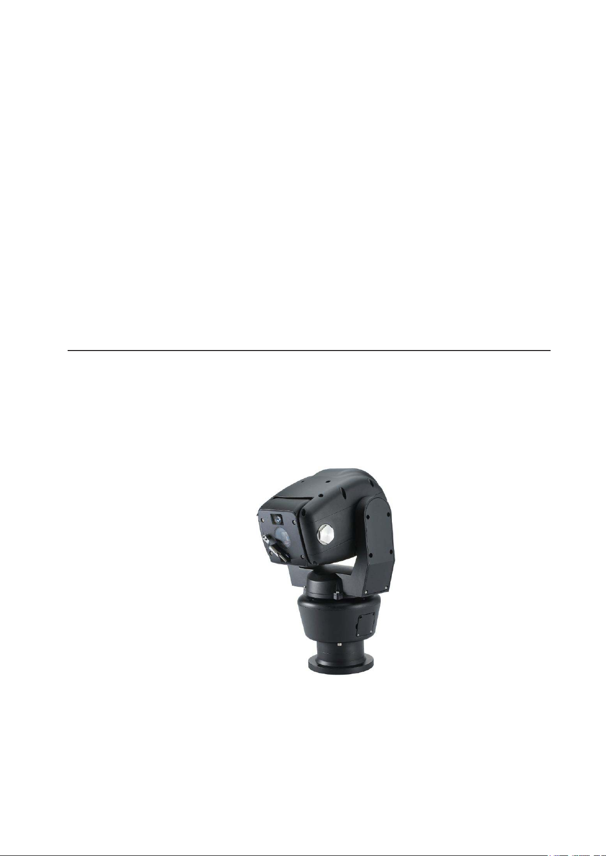
Robo Ruggedized PTZ
Instruction Manual Version 3.1
Please read this manual carefully before installation and operation of the product.
Page 2

Table of Contents
1. INTRODUCTION 4
2. SAFETYWARNING 5
3. PACKINGLIST 6
4. MOUNTING 8
• Mounting Options (UK Column Mounting)
• Offset Mounting
• Changing the Wiper
• 14 Pin Cable Connection
5.TELEMETRYCONTROL 11
• On-Board Protocols
• DIL (Dual In-Line) Switches
• Protocol Settings
• Baud Rate Settings
• RS485 Address Settings
• RS485 Termination
• Keyboard Operation
6.SETUPMENUOVERVIEW 16
MAINMENU 21
• PAN TILT SET
• ID DISPLAY
• P/T DISPLAY
• CAMERA NAME
• MANUAL SPEED
• PROPO. P/T
• DIGITAL FLIP
• IMAGE HOLD
• INSTALLATION
• AUTO REFRESH
• EXIT
2
Page 3

• CAMERA SET
• ALARM SET
• WDR
• MOTION DET
• ATW
• FOCUS / ZOOM
• AE
• DAY & NIGHT
• SPECIAL
• EXIT
• AUTOSEQ SET
• PRESET
• TOUR
• SCAN
• PATTERN
• AUTO PAN
• AUTO RUN
• ALARM DISPLAY
• ALARM IN
• ALARM OUT
• TIME OUT
• EXIT
• WIPER SET
• WIPER RUN
• EXIT
• INITIALISE SET
• POWER ON RESET
• PAN / TILT INIT
• CAMERA INIT
• AUTO SEQ INIT
• PRIVACY ZONE INIT
• HOME POSITION
• EXIT
• FACTORY INIT
• EXIT
• ZONE SET
• AREA SEL
• AREA DEFINE
• AREA COLOUR
• AREA NEW SET
• HEIGHT EDIT
• WIDTH EDIT
• PAN ANGLE
• TILT ANGLE
• EXIT
7. SPECIFICATION 46
8. DIMENSIONS 47
3
Page 4

1. Introduction
This unit is designed to provide clear video images, even in extreme conditions. A robust mechanism,
allied with the latest technology, offers excellent auto-focus during PTZ operations. Exact location control,
following preset programmed operations, high-speed zoom and auto focus capabilities for shooting
moving objects, are just some of this camera’s features. The at window and over 700TVL provide a vivid
picture quality, and the zoom interlocked Target IR LED technology gives outstanding performance when
monitoring night time environments; it also features 512x Super WDR.
Long-distance objects are easily distinguished with the outstanding performance of the Sony 36x Optical
and 32x Digital Zoom; total Power Zoom capability of 1152x. The IR models have x2 High Intensity
“Target” Infra-Red LED’s that fully integrate with the camera’s 36x zoom module, giving extremely detailed
images at night time. During a zoom operation the LED coverage changes proportionately with the zoom
of the camera. The angle of LED coverage goes from 60 degrees at its widest part to 6 degree at its
narrowest. This minimises light pollution and eliminates IR illumination of unimportant areas. Medium to
long range targets become the true focal point for the camera lens and the LED’s. There is also a built-in
and adjustable de-fog function which enhances images in foggy or misty environments.
Features
• 1/4” Sony Super HAD CCD
• Powerful Night Vision - up to 100m in Ideal Conditions – IR Models Only
• Target IR LED’s (IR angle 6~60 degrees; synchronised with the optical zoom ratio) – IR Models Only
• Embedded and Adjustable Defog and Image Enhancer
• 512x Wide Dynamic Range (WDR)
• 2D and 3D DNR (Digital Noise Reduction)
• 36x Optical Zoom and 32x Digital Zoom – total 1152x Power Zoom capability
• 360 Degree Endless Panning
• Wide Tilt Range of -25~205 Degrees
• True Day/Night with IR Cut Filter
• 128 Presets and Tour Function
• DIS (Digital Image Stabiliser)
• Integrated Heater/Blower for -40°C and +60°C Operation
• High Performance & Low-Noise Wiper, with Anti-Abrasion Soft Silicon Rubber
• Hydrophobic Surface Coated Flat Glass
• Anti-Corrosion, Anti-Saltwater Powder Coated Surface Finish
• Auto Digital Flip
• 8 Privacy Zones
• IP68 Rated
• Upright and Pendant Installation Mounting Option.
4
Page 5
2. Safety Warning
* The purpose of this information is to ensure proper use of this product and to prevent danger and
damage to persons and property. Please observe all precautions.
* The precautions are divided into “Warnings” and “Cautions” as distinguished by the symbols shown
below;
Warning: Ignoring these warnings may result in death or serious injury.
Caution: Ignoring these cautions may result in injury or damage to property.
Caution: Instructions alert you to the
potential risk of injury or
damage to property
Warning: Instructions alert you to the
potential risk of death or
serious injury
Warning
1. Only use the standard Power Adapter ) Using any other adapter
could cause re, electrical shock, or damage to the product, and invalidate the warranty.
2. Before connecting the power supply, and signal wires, make sure the external connections are
isolated. Connect the alarm signal wires to the alarm terminals, the communication wires to the
terminal block and the AC adapter to the AC power input receptacle (incorrectly connecting the
power supply may cause re, electrical shock, or damage to the product).
3. Do not connect multiple cameras to a single Power Adapter. Exceeding the adapter’s current
capacity can cause abnormal heat generation or re.
4. Securely plug, or connect, the power cord into the power receptacle. An insecure or loose connection
may cause a re.
5. When installing the camera on a wall or ceiling etc. fasten it securely using suitable anchor bolts
and/or xings. An unsecured camera could fall and cause serious personal injury, or even a fatality.
6. Do not place conductive objects (e.g. screwdrivers, coins or other metal objects) inside any part of
the camera. Doing so may cause personal injury, a re or an electrical shock.
7. Do not install the unit in humid or dusty locations. Doing so may cause a re or electrical shock.
8. If any unusual smells or smoke come from the unit, stop using the product immediately, disconnect
the camera from the power source and contact your distributor.
9. If this product fails to operate normally, contact your distributor. Never disassemble or modify
this product in any way.
10. Always clean the camera with water and wipe the surface dry with a soft lint free cloth. Never use
detergents or chemical agents on the product, as this may result in discolouration of the painted
surface or cause damage to the nish.
5
Page 6
Caution
1. Do not drop objects on the product, or apply strong shocks to it. Keep away from locations subject
to excessive vibration or magnetic interference.
2. Do not install in locations subject to a continual high temperature range (over 50°C), continual low
temperature (below -40°C) or high humidity.
3. Avoid locations which are exposed to direct sunlight, radiation or near heat sources such as heaters or radiators.
4. If an already installed product needs to be relocated, make sure the power is turned off before it is
moved.
5. Always try and install in a well-ventilated environment.
6. Make sure the camera is adequately protected against lightning strikes by using a suitably rated
surge protector, which must be locally grounded. Failure to do so could irreparably damage the
camera, and any attached communication and telemetry equipment.
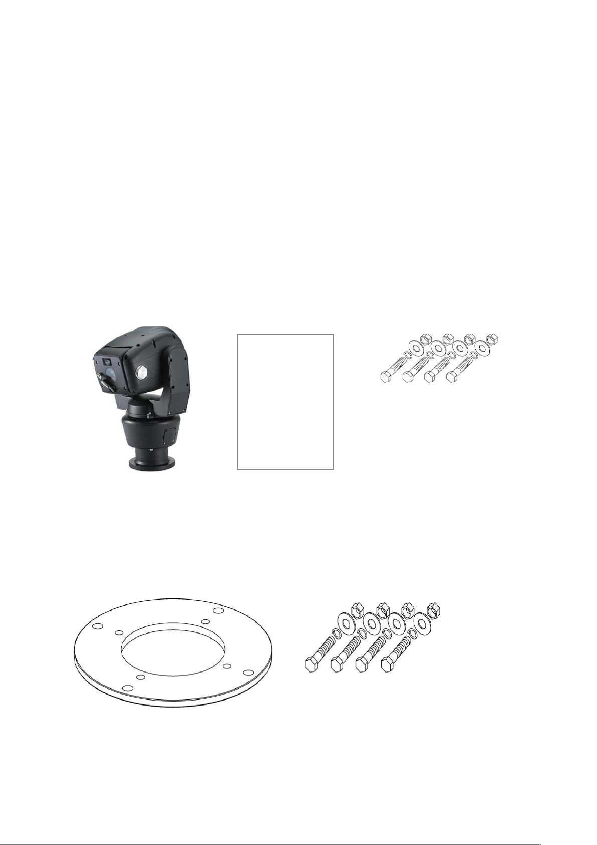
3. Packing List
Wide Dynamic 36x Zoom
Rugged PTZ Camera x1
Option (UK Column Mounting)
Hex Bolt / Nylon Nut / Spring
Washer / Plate Washer
-M8 x 35 (SUS) x4
Instruction Manual x1
Adapter Plate
Hex Bolt / Nylon Nut / Spring Washer /
Plate Washer
6
Page 7
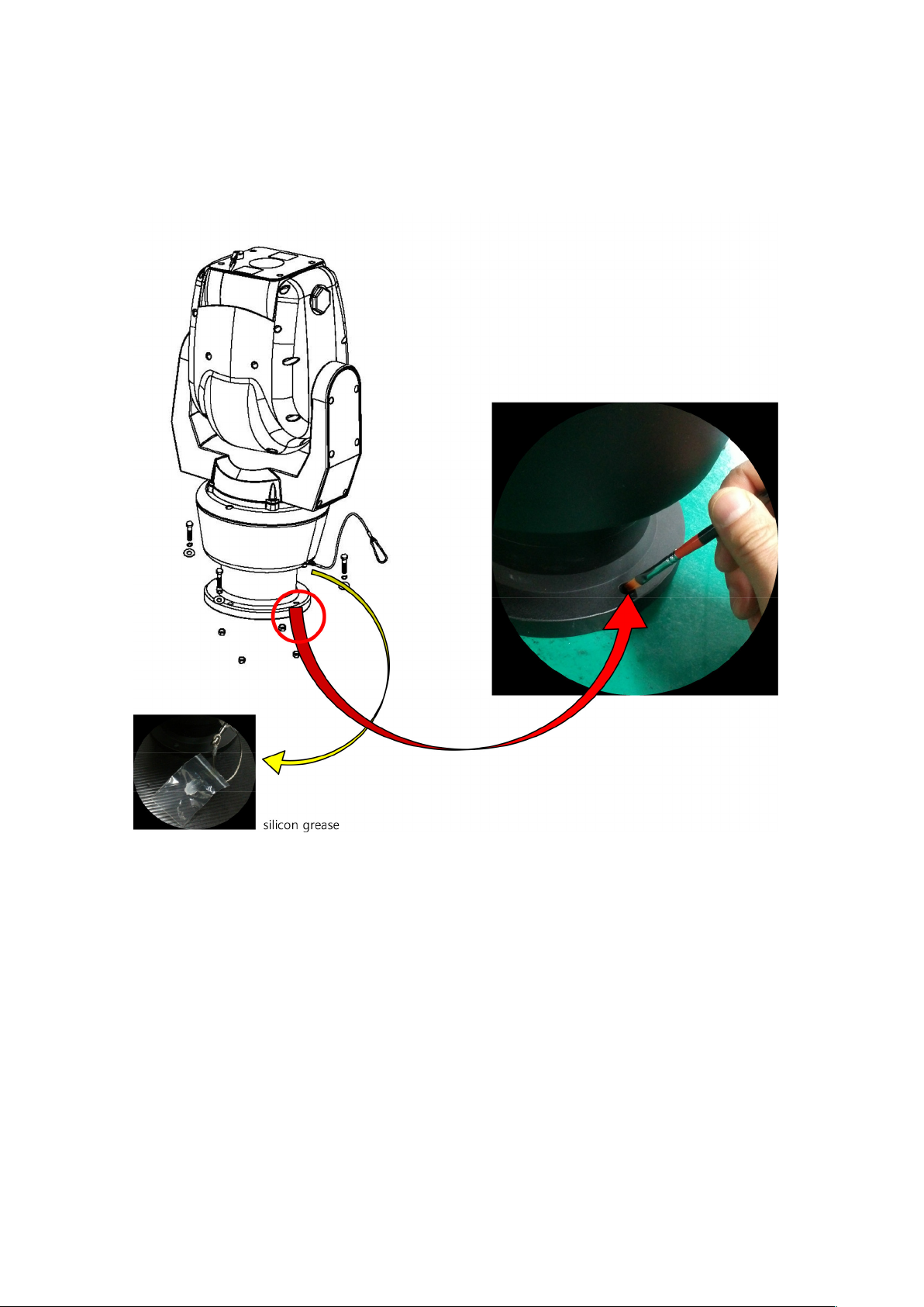
Instruction
Please put the supplied anticorrosive silicon grease over the edge area on each screw hole of the PCD
adapter plate before using M8 Hex Bolts.
7
Page 8
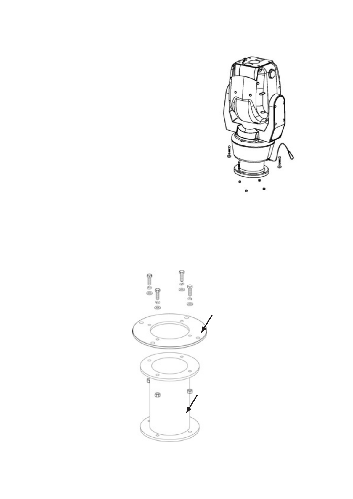
4. Mounting
This unit is designed for installation in the upright or inverted
position. It is a heavy duty mechanism and requires a secure
and safe installation surface, and we recommend installers
use brackets, towers and columns which comply with the
industrial standard - 4” (142.0mm) PCD.
Cable connections are made using the camera base.
The camera base is supplied with a 4” (142.0mm) PCD
adapter plate and connects to a bracket or tower using three
M8 Hex Bolts, s/w, p/w and Nylon Nuts, with Spring and Plate
Washers.
• Mounting (Locally procured )
The camera is supplied with an adapter, 4” (101.6mm) PCD, which complies with the uniform standard
for UK Pole or Column camera mounts.
Adapter Plate
UK Column
Mounting
8
Page 9
A Safety Wire, made from stainless steel, is provided for securing the Robo PTZ
during installation and maintenance visits; to prevent damage and injury.
During installation and maintenance visits, please make sure the Safety Wire is
rmly connected to a secure xing.
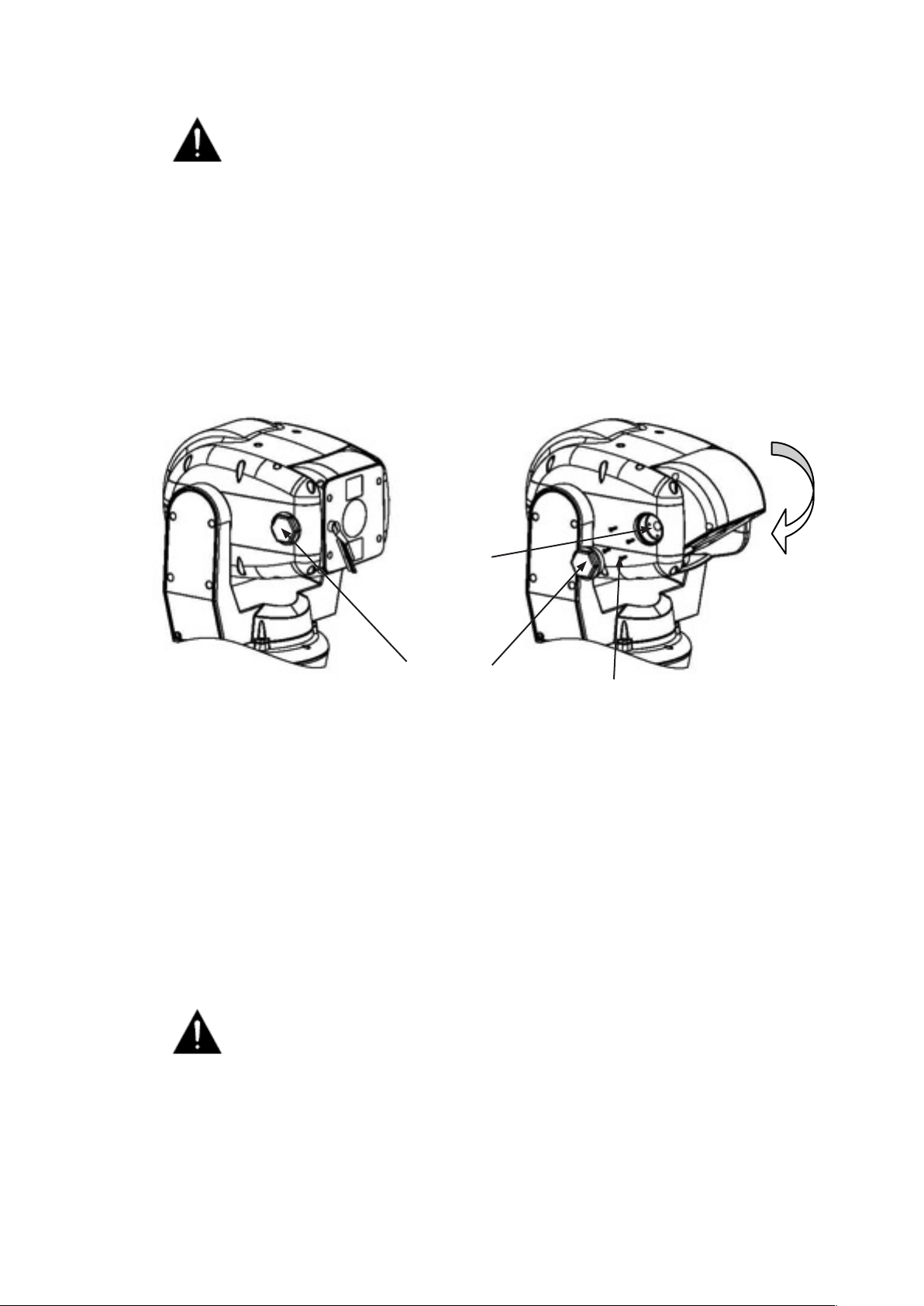
• Offset Mounting
When an installation requires the camera module to be tilted down – to obtain an angle of view
immediately below Robo PTZ – the following procedure MUST be followed. We recommend using a local
test monitor to check the viewing angle before nally xing the module into position.
Master
Keylock
Tilt 90°
Hex Bolt
Retaining M3 Screw
Undo the Hex Bolt, using a 36mm Spanner, when the camera is in 0° Tilt.
Then, using a screwdriver, undo the 4 x M3 Retaining Screws.
Completely remove the silver Master Keylock Cog – failure to do so will result in irreparable
damage to the camera head.
After tilting down the camera module to the required angle, replace the Master Keylock Cog (this is
keyed and only can be located in a unique position), the M3 Retaining Screws and the Hex Bolt. The
Torque setting for the Hex Bolt is 0.84Kg/m.
DO NOT excessively tighten the Retaining Screws or Hex Bolt.
9
Page 10
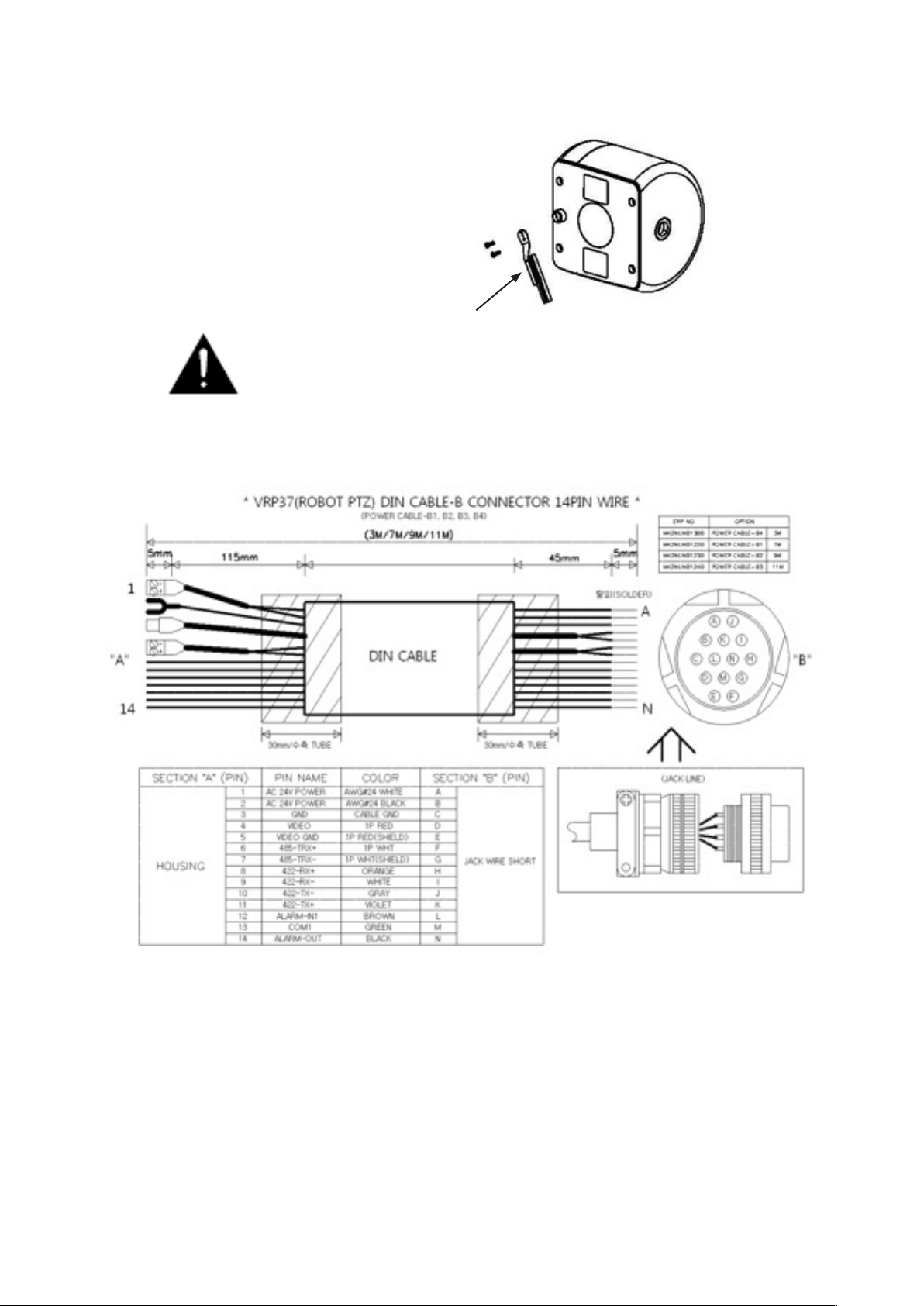
• Changing the Wiper
The Wiper can be removed, changed and replaced
by undoing the two retaining screws.
Wiper
Please keep the window glass clean to maintain clear images.
• 14-Pin Cable Connection
5. Telemetry Control
This unit is designed with a range of diverse Telemetry Control systems, based on compatibility with
industrial standard protocols. It works by using these integrated protocols directly, or via 3rd party
protocol converters.
Telemetry Control is via way of RS485 or Coaxial based video transmission equipment. Some limitation
on protocols and/or software changes may not guarantee to take full advantage of all the features from
the manufacturer, and may limit features and operation of the Robo PTZ
When the Telemetry Control is based on RS485, the address range is limited to 127.
10
Page 11
• On-Board Protocols
This unit provides On-Board Protocols, including:
• BBV 422
• Pelco D
• Pelco P
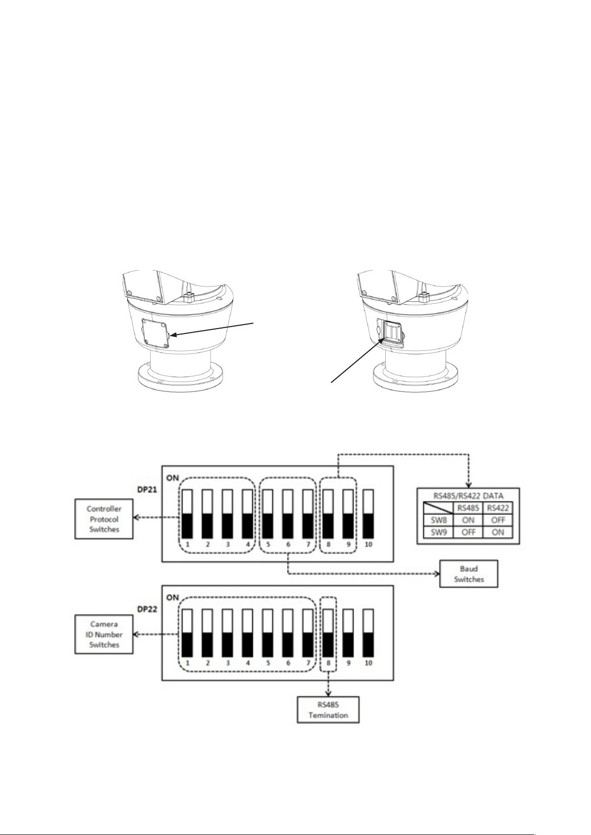
• DIL (Dual In-Line) Switches
Two 8-way DIL Switches are contained within a waterproofed cover on the camera body; these
are used to select the camera address, communication protocol and baud rate.
Cover Retained by
Four Screws
Screws and
Cover Removed
11
Page 12
• Protocol Settings
Protocol is selected using switches DP21-1, DP21-2, DP21-3 and DP21-4.
The conguration of the Protocol is as follows.
When an installer uses a protocol based Coaxial cable, it isn’t using a RS485 Address so you
can leave the Address as 0
Description No DP21-1 DP21-2 DP21-3 DP21-4 Apply
PELCO-D 0 OFF OFF OFF OFF OK
PELCO-P 1 ON OFF OFF OFF OK
BBV 2 OFF ON OFF OFF OK
VCL 3 ON ON OFF OFF OK
PANASONIC 4 OFF OFF ON OFF OK
AD 5 ON OFF ON OFF OK
HONEYWELL 6 OFF ON ON OFF OK
SAMSUNG 7 ON ON ON OFF OK
FVISION 8 OFF OFF OFF ON OK
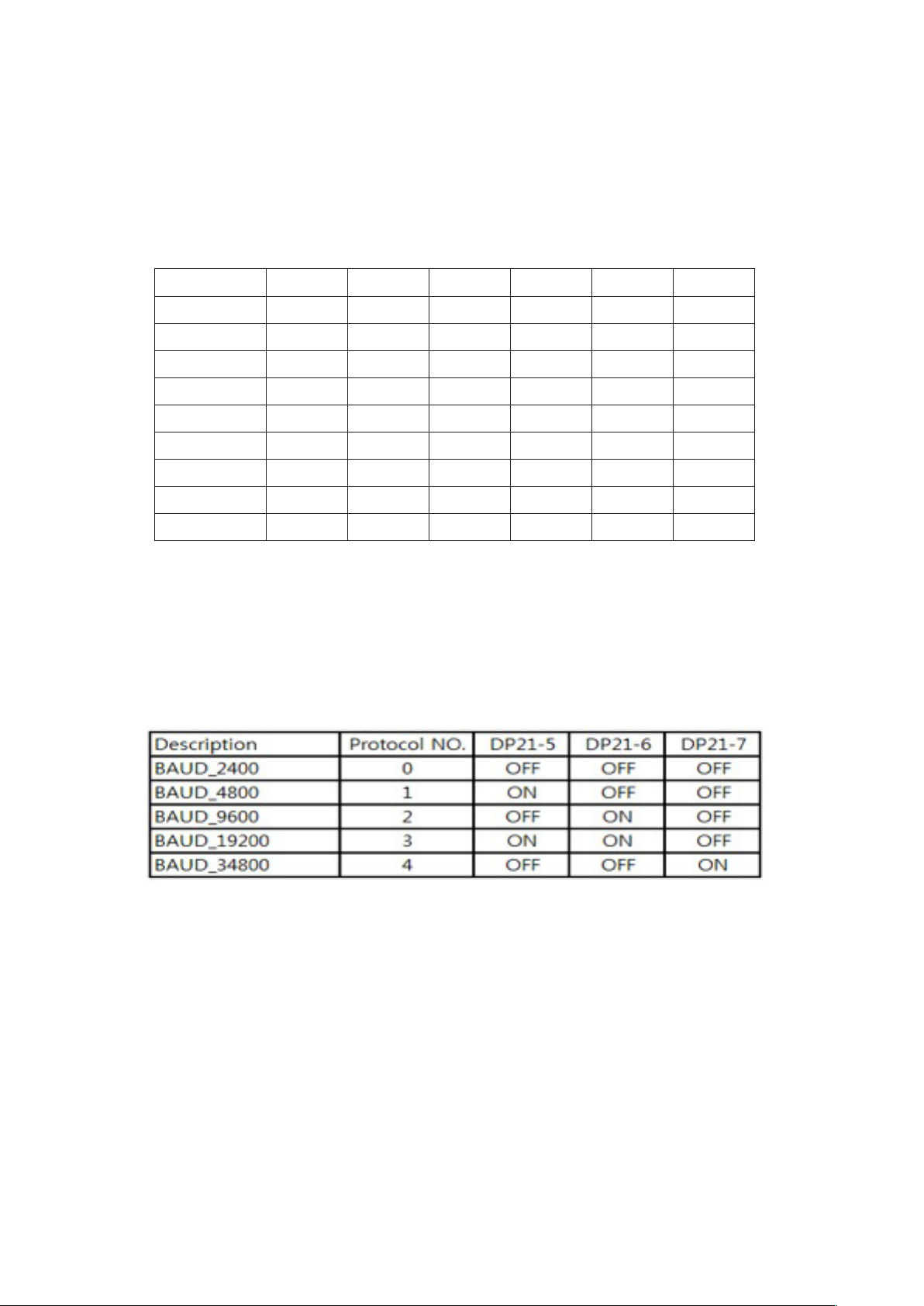
• Baud Rate Settings
The Baud Rate, communication speed, is selected using switches DP21-5, DP21-6 and DP21-7.
Baud Rate conguration settings are as follows:
12
Page 13

• RS485 Address Settings
ID setting for DP22 switches SW1~SW7 DIP Switch setting 1-ON, 0-OFF
DIP SW ID DIP SW ID DIP SW ID
1000000 1 1010100 21 1001010 41
0100000 2 0110100 22 0101010 42
1100000 3 1110100 23 1101010 43
0010000 4 0001100 24 0011010 44
1010000 5 1001100 25 1011010 45
0110000 6 0101100 26 0111010 46
1110000 7 1101100 27 1111010 47
0001000 8 0011100 28 0000110 48
1001000 9 1011100 29 1000110 49
0101000 10 0111100 30 0100110 50
1101000 11 1111100 31 1100110 51
0011000 12 0000010 32 0010110 52
1011000 13 1000010 33 1010110 53
0111000 14 0100010 34 0110110 54
1111000 15 1100010 35 1110110 55
0000100 16 0010010 36 0001110 56
1000100 17 1010010 37 1001110 57
0100100 18 0110010 38 0101110 58
1100100 19 1110010 39 1101110 59
0010100 20 0001010 40 0011110 60
1011110 61 0010101 84 1101011 107
0111110 62 1010101 85 0011011 108
1111110 63 0110101 86 1011011 109
0000001 64 1110101 87 0111011 110
1000001 65 0001101 88 1111011 111
1100001 67 0101101 90 1000111 113
0010001 68 1101101 91 0100111 114
1010001 69 0011101 92 1100111 115
0100001 66 1001101 89 0000111 112
0110001 70 1011101 93 0010111 116
1110001 71 0111101 94 1010111 117
0001001 72 1111101 95 0110111 118
1001001 73 0000011 96 1110111 119
0101001 74 1000011 97 0001111 120
1101001 75 0100011 98 1001111 121
0011001 76 1100011 99 0101111 122
13
Page 14
DIP SW ID DIP SW ID DIP SW ID
1011001 77 0010011 100 1101111 123
0111001 78 1010011 101 0011111 124
1111001 79 0110011 102 1011111 125
0000101 80 1110011 103 0111111 126
1000101 81 0001011 104 1111111 127
0100101 82 1001011 105
1100101 83 0101011 106
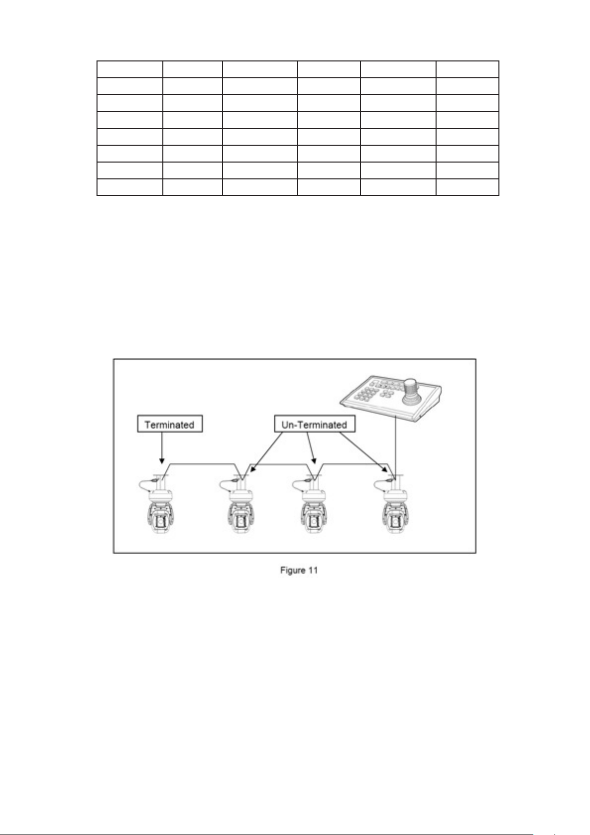
• RS485 Termination
If Robo PTZ is using RS485 communication, please make sure the Bus is correctly installed and congured
to prevent malfunctions. The maximum allowed cable distance is 1200 metres. A Maximum of 32 units
can be connected to a cable section.
Any cable type which exceeds the specication of EIA RS485 can be used. The furthest device, by cable
length, should be terminated in accordance with the specication. Other devices should remain un-
terminated (see Figure 11 below).
• Keyboard Operation
Key Sequences and Joystick movements are executed to closely control the camera and program the
Telemetry Control system of Robo PTZ. Examples of these are PRESET and TOUR.
If a Keyboard cannot be used to access and change the camera parameters, most characteristics are
accessible through the camera’s OSD menu.
Note – Changing a Keyboard’s Software and/or Protocol can effect alterations to the camera’s
operability. The Robo PTZ manufacturer absolves itself of responsibility for such modications.
14
Page 15
6. Setup Menu Overview
In this chapter, we will look at the overall structure of the Setup Menu and then later look at the function
of each menu.
MAIN MENU
PAN / TILT
SET
CAMERA
SET
WDR WDR MODE OFF / ON
ID DISPLAY ON / OFF
P/T DISPLAY OFF / ON
CAM NAME OFF / ON
MANUAL SPEED 10~110° /SEC
PROPO. P/T ON / OFF
DIGITAL FLIP ON / OFF
IMAGE HOLD OFF / ON
INSTALLATION NORMAL / INVERT
AUTO REFRESH 5~240
EXIT
WDR LEVEL 1~7
MD
ATR LEVEL LOW / MID / HIGH
EXIT
MD DEFINE
MD DISPLAY
SENSITIVITY
INTERVAL T
AREA START H
AREA START V
AREA END H
AREA END V
OFF / ON
OFF / ON
1~25
1 SECOND ~ 4 MINUTES
0~XX
0~XX
XX~12
XX~8
EXIT
15
Page 16

CAMERA
SET
ATW ATW MODE AUTO / ATW / INDOOR /
OUTDOOR / ONEPUSH /
MANUAL
ONE PUSH TRG SET
MANUAL RED 0~255
MANUAL BLUE 0~255
EXIT
FOCUS
/ ZOOM
FOCUS MODE AUTO / ZOOMTG / MANUAL /
ZOOM
AF SENSITIVE NORMAL / LOW
DIG ZOOM OFF / ON
ZOOM SPEED 1~8
ZOOM RATIO ON / OFF
AF LIMIT <BW> ON / OFF
EXIT
AE AE MODE AUTO / SHUTTER / MANUAL
IRIS CLOSE~F1.6
GAIN 0~15
BRIGHTNESS 1~15
SHUTTER 1/50~1/100000
SLOW SHUTTER OFF / ON
FLICKERLESS OFF / ON
BLC OFF / ON
L-LUMINANCE OFF / ON
EXIT
16
Page 17

CAMERA
SET
DAY & NIGHT MODE AUTO / DAY / NIGHT
DELAY 5~60 SEC.
THRESHOLD 1~29
GAP 1~5
BURST ON / OFF
IR LED ANGLE AUTO / 60.0,57.0, 55.0, 51.0,
47.0, 40.0, 37.0, 33.0, 28.0,
23.0, 20.0,15.0,10.0,8.0,6.0
EXIT
SPECIAL STABILISER OFF / ON
HR OFF / 1~7
IMAGE FLIP OFF / ON
IMAGE MIRROR OFF / ON
SHARPNESS 0~14
2D-DNR AUTO, OFF~15
3D-DNR AUTO, OFF~15
HLC OFF / ON
ON
LEVEL LOW / MID / HIGH
CLIP LEVEL 1~7
EXIT
DEFOG OFF / AUTO / USER
AUTO
AUTO LEVEL 1~10
EXIT
USER
FOG LEVEL 0~15
FOG GAMMA 0~15
STRENGTH 0~64
UVSTRENGTH 0~13
NOISESUP 0~64
EDGE LEVEL 0~15
EXIT
EXIT
17
Page 18

CAMERA
SET
PRESET PRESET NO 1~128
PRESET DEFINE OFF / ON
PRESET NAME OFF / ON
P/T POSITION XXX / XXX
FOCUS IN BW AUTO / ZOOMTG / MANUAL
WDR OFF / ON
ATW SET
EXIT
TOUR
SET
SCAN
TOUR NO 1~5
TOUR NO DEF OFF / ON
NAME TOURGROUP 1
TOUR NAME DEF OFF / ON
DWELL TIME 1~120
EXIT
SCAN NO 1~5
SCAN DEFINE OFF / ON
NAME SCANGROUP 1
SCAN NAME DEFINE OFF / ON
PAN START POS 180
PAN END POS 350
TILT POS 45
SCAN SPEED 2°, 5°, 10°, 20° /S
EXIT
PATTERN PATT NUMBER 1~2
PATT DEFINE OFF / ON
NAME PATTERN001
PATT NAME DEF OFF / ON
PATT RECORD OFF / ON
PATT SPEED 2°, 5°, 10°, 20° /S
EXIT
18
Page 19

CAMERA
SET
AUTO PAN TILT ANGLE XXX
PAN SPEED 2°, 5°, 10°, 20° /S
DIRECTION CW / CCW
EXIT
AUTORUN OFF / SEQ / TOUR / SCAN / PATT / A.PAN
HOMEPOSITION OFF / 1~128
EXIT
ZONE SET AREA SELECT 1~8
AREA DEFINE OFF / ON
AREA COLOUR BLACK~MOSAIC
AREA NEW SET OFF / ON
HEIGHT EDIT XXX
WIDTH EDIT XXX
PAN ANGLE XXX
TILT ANGLE XXX
EXIT
ALARM SET ALARM DISPLAY OFF / ON
ALARM IN SET
ALARM OUT OFF / ON
TIME OUT 1~10 SECONDS
EXIT
WIPER SET WIPER RUN AUTO / PUSH / RUN / STOP
EXIT
INITALISE SET POWER ON RESET
PAN / TILT INIT
CAMERA INIT
AUTOSEQ INIT
PRIVACY ZONE INIT
FACTORY INIT
EXIT
19
Page 20

System information
The diagrams shown in the previous section illustrated the overall structure of the setup menu. In this
section, descriptions of the features within the setup menu will enable users of the camera to tailor it to
their personal needs.
MAIN MENU
1. PAN TILT SET
2. CAMERA SET
3. AUTOSEQ SET
4. ZONE SET
5. ALARM SET
6. WIPER SET
7. INITIALISE SET
8. EXIT
1. PAN TILT SET
1. ID DISPLAY ON / OFF
2. P/T DISPLAY ON / OFF
3. CAMERA NAME OFF / ON
4. MANUAL SPEED 10~110° / SECOND
5. PROPO. P/T ON / OFF
6. DIGITAL FLIP ON / OFF
7. IMAGE HOLD OFF / ON
8. INSTALLATION NORMAL / INVERT
9. AUTO REFRESH 5~240
10. EXIT
Selection: UP, DOWN, LEFT & RIGHT KEYS
Menu Open: IRIS OPEN KEY
Menu Close: IRIS CLOSE KEY
20
Page 21

• ID DISPLAY - Camera ID
OFF: The Camera ID does not appear on the screen.
ON: The Camera ID is displayed on the screen.
To change the position of the camera ID press the IRIS OPEN KEY. When ID is set to ON it’s
possible to move to the ID DISPLAY Menu, and thereby change the position.
• P/T DISPLAY
The PAN/TILT angle is displayed on the bottom right hand side of the screen.
• CAM NAME
A maximum of 10 characters can be input. When changing the camera name, press the
IRIS OPEN Key after NAME DISPLAY is set to ON.
• MANUAL SPEED
Adjustable maximum speed when PAN/ TILT are manually controlled.
• PROPO. P/T
Automatically adjusts the PAN/TILT movement speed according to the Zoom magnication level.
OFF: PAN/TILT movement is not automatically controlled.
ON: The PAN/ TILT speed slows down on higher zoom magnication.
• AUTO FLIP
OFF: Operates when TILT is below 90°.
ON: Operates when TILT is over 90°.
• IMAGE HOLD
When moving to a preset, the screen displays the frozen image of the last displayed preset position.
OFF: Displays the current image.
ON: Displays the frozen image.
Caution - FREEZE works during a SEQ, TOUR in AUTORUN MODE.
• AUTO REFRESH
Should a PAN/TILT operation overrun its setting value, AUTO REFRESH automatically compensates.
21
Page 22

• INSTALLATION
NORMAL: When the camera is installed upright; as shown left.
INVERTED: When the camera is installed pendant style; as shown left.
Caution – Tilt Angle: Factory Default (-25 ~ 205 degrees) ☞ Tilt angle is limited to -25~90
degrees after setting a zone.
1.1.1 DISPLAY
ID location can be changed as follows.
1. Select ON from ID DISPLAY.
2. Press IRIS OPEN KEY.
MOVE: U/D/L/R
EXIT: IRIS CLOSE
Selection: UP, DOWN, LEFT & RIGHT KEYS
Menu Open: IRIS OPEN KEY
Menu Close: IRIS CLOSE KEY
PressIRISCLOSEKEYwhennished.
1.2 CAMERA NAME DISPLAY
CAMERA NAME MAINCAMERA
0123456789ABCDEFGH
IJKLMNOPQRSTUVWXYZ
DELETE IRISOPEN
POSITION IRISOPEN
EXIT
Selection: UP, DOWN, LEFT & RIGHT KEYS
Menu Open: IRIS OPEN KEY
Menu Close: IRIS CLOSE KEY
22
Page 23

The method for naming a Camera is as follows:
1. Select DELETE and cancel MAINCAMERA by pressing the IRIS OPEN KEY.
2. Move to the desired alphanumeric and press the IRIS OPEN KEY.
3. If you want to change the location of the camera name, select POSITION and press the IRIS
OPEN KEY. The method for changing the position of the camera name is the same as in ID
DISPLAY.
2. CAMERA SET
1. WDR................................
2. MOTION DET .................
3. ATW ................................
4. FOCUS/ZOOM ...............
5. AE ...................................
6. DAY & NIGHT .................
7. SPECIAL .........................
8. EXIT
2.1 WDR SETUP
1. WDR MODE OFF / ON
2. WDR LEVEL 1~7
3. ATR LEVEL LOW/MIDDLE/HIGH
SET
SET
SET
SET
SET
SET
SET
4. EXIT
• WDR MODE
OFF: WDR doesn’t work.
ON: WDR is activated.
• WDR LEVEL
Adjusts the brightness when WDR is activated.
• ATR LEVEL
Adjusts the contrast in dark areas.
23
Page 24

2.2 MOTION DETECTION
1. MD DEFINE OFF / ON
2. MD DISPLAY OFF / ON
3. SENSITIVITY 1~25
4. INTERVAL T 1 SEC ~ 4 MINUTES
5. AREA START H 0~XX
6. AREA START V 0~XX
7. AREA END H XX~12
8. AREA END V XX~8
9. EXIT
• MD DEFINE
When DEFINE is ON, MD is activated.
• MD DISPLAY
If MD DISPLAY is set to ON, “MOTION” appears on the bottom right hand side of the screen.
Motion Detection doesn’t work when the OSD MENU is activated.
• SENSITIVITY
The Motion Detection sensitivity level is adjustable.
As the sensitivity level increases the possibility of false activations also increases.
• INTERVAL T
MD is re-activated, according to the set time, after motion has been detected.
• AREA START H, AREA START V
Set a start area for Motion Detection.
• AREA END H, AREA END V
Set an end area for Motion Detection.
Caution
1. Motion Detection doesn’t work in SCAN & PATTERN settings.
2. When using MD, the DWELL TIME should be a minimum of 3 seconds in TOUR settings.
3. Do not set MD if an unstable light source is present e.g. ickering light.
4. Instant changes in light sources may cause false activations e.g. turning lights on or off.
5. This MD function is not intended for re or antitheft protection and the manufacturer frees
itself from any responsibility should it malfunction.
24
Page 25

2.3 ATW
1. ATW MODE AUTO-MANUAL
2. ONE PUSH TRG SET
3. MANUAL RED 0 ~ 255
4. MANUAL BLUE 0 ~ 255
5. EXIT
Menu Shift : UP, DOWN, LEFT &RIGHT KEYS
Menu Open: IRIS OPEN KEY
Menu Close: IRIS CLOSE KEY
A White Balance setting must be specied and be appropriate for the ambient lighting
conditions.
• ATW MODE AUTO
White Balance is automatically compensated.
• ATW MODE ] ATW
White Balance is automatically compensated when the colour temperature range is
2500°K~9500°K.
• ATW MODE ] OUTDOOR
White Balance is optimised for an outdoor environment.
• ATW MODE ] INDOOR
White Balance is optimised for an indoor environment.
• ATW MODE ] ONE PUSH
White Balance is optimised for the current lighting conditions. If the lighting conditions
change, the White Balance should be readjusted. It operates by pressing the IRIS OPEN KEY
when SET is on.
• ATW MODE ] MANUAL
White Balance is manually adjustable using the RED and BLUE gain controls.
25
Page 26

2.4 FOCUS/ZOOM
1. FOCUS MODE AUTO/ZOOMMTG/MANUAL
2. AF SENSITIVE NORMAL/LOW
3. DIG ZOOM OFF / ON
4. ZOOM SPEED 1~8
5. ZOOM RATIO ON / OFF
6. AF LIMIT BW ON / OFF
7. EXIT 7. EXIT
• FOCUS MODE
AUTO
FOCUS is adjusted automatically.
MANUAL
FOCUS is adjustable manually.
ZOOMTG
Whenever ZOOM changes, the FOCUS also changes.
• AF SENSITIVE
NORMAL
Focus is adjusted normally.
LOW
Drop the Auto Focus sensitivity to reduce the number of AF operations.
• DIG ZOOM
Digital Zoom activates at the maximum level of the Optical Zoom; if the user keeps pushing
the “Tele” button.
• ZOOM SPEED
Adjusts the zoom tracking speed.
• ZOOM RATIO
Displays the zoom ratio on the top right hand side of the screen.
26
Page 27

• AF LIMIT BW (limited operation of Auto Focus)
The auto-focus function may not operate normally under the following conditions;
When the background illumination is too low, or too high.
While Slow-Shutter is in operation.
If the Zoom level is set too high.
If a long distance object and a close distance object appear together within a
monitoring area.
If there is no contrast in the scene i.e. looking at the sky or a wall.
If the camera is pointed toward a thin horizontal line.
Auto Focus focuses on an object in the centre of the screen; objects around the screen
edges may not be properly in focus.
If the IR LED’s are ON and the Zoom Ratio is over 20x, the focus mode will be set to
manual, regardless of the focus mode settings, in order to stabilise the focus.
OFF: AF operates with the FOCUS MODE set in the FOCUS/ZOOM MENU on the OSD
ON: This function is useful when IR LED’s are ON and Zoom Ratio goes over 20x. FOCUS
MODE changes to MANUAL in this condition.
Caution
This function holds good when “TOUR, SEQ” is “ON” also.
If AF LIMIT BW is “ON” when IR is activated, AF will be operated as MANUAL FOCUS even
if FOCUS MODE under PRESET is set to “AUTO”.
2.5 AE
1. AE MODE AUTO/SHUTTER/MANUAL
2. IRIS CLOSE ~F1.6
3. GAIN 0 ~ 15
4. BRIGHTNESS 1 ~ 15
5. SHUTTER 1/50 ~ 1/100000
6. SLOW SHUTTER OFF / ON
7. FLICKERLESS OFF / ON
8. BLC OFF / ON
9. L-LUMINANCE OFF / ON
10. EXIT
27
Page 28

• AE MODE
AUTO
IRIS and GAIN are controlled automatically. Shutter speed is xed at 1/50sec (PAL).
SHUTTER
IRIS and GAIN are controlled automatically. Shutter speed can be adjusted manually.
In order to suppress FLICKER, user can set a shutter speed of 1/100sec (PAL).
MANUAL
Users can control the IRIS, GAIN and SHUTTER manually.
• BRIGHTNESS
Adjust the brightness used for AE MODE.
• SHUTTER
When capturing fast moving subjects, or under low light conditions, users can adjust the
shutter speed up or down to get improved image quality.
• SLOW SHUTTER
When AE MODE is AUTO and the brightness is decreased, shutter speed is set automatically
OFF (AUTO)
Under low light conditions, shutter speed is automatically controlled according to the brightness
of the scene.
ON (MANUAL)
Under low light conditions, shutter speed is controlled according to a set point.
• BLC
This function is useful if the subject shows dark against a bright background.
• FLICKERLESS
When FLICKLESS is ON, in order to suppress a FLICKER, the shutter speed is set to
1/100sec (PAL).
• L-LUMINANCE
The L-Luminance function makes the entire image brighter. When this function is ON the
visibility of the image increases, but as it makes scenes brighter it may also look out of focus.
28
Page 29

2.6 DAY & NIGHT
1. MODE AUTO / COLOUR / BW
2. DELAY 5~60 SECONDS
3. THRESHOLD 1~29
4. GAP 1~5
5. BURST ON / OFF
6. IR LED ANGLE AUTO / 60.0°~6.0°
7. EXIT
• MODE
AUTO ] Automatically turns to Colour during daytime and B/W at night.
COLOR ] Fixed in Colour mode. IR’s are OFF.
BW ] Fixed in BW mode. IR’s are ON.
• DELAY
Set the switching time from B/W to Colour and from Colour to B/W; necessary for stabilisation.
• THRESHOLD
AGC level in Day & Night mode for turning from Colour to B/W. A higher threshold value
makes an earlier change from Day to Night at lower AGC levels (i.e. In brighter conditions).
• GAP
The gap level when switching between “Colour to B/W mode” and “B/W to Colour mode”.
• BURST
Output the BURST signal when switching to B/W mode.
• IR LED ANGLE
AUTO ] IR LED ANGLE is controlled automatically according to the ZOOM ratio.
60.0 ] IR LED ANGLE is xed at 60 degrees.
6.0 ] IR LED ANGLE is xed at 6.0 degrees. This is useful for monitoring an object in the far
distance – must be more than 30 metres away.
Caution
If users set the IR LED ANGLE at 60/6, the IR LED ANGLE is xed at a set point when AUTO
RUN is working; only used on models with integral IR LED’s.
29
Page 30

2.7 SPECIAL
1. STABLISER OFF / ON
2. HR OFF / 1~7
3. IMAGE FLIP OFF / ON
4. IMAGE MIRROR OFF / ON
5. SHARPNESS 0~14
6. 2D-DNR AUTO / OFF~15
7. 3D-DNR AUTO / OFF~15
8. HLC OFF / ON
9. DE-FOG OFF / AUTO / USER
10. EXIT
• STABLISER
ON ] Set to “ON” to mitigate vibrations when the camera is installed in an unstable
environment - such as, mounted on a pole which is subject to movement.
• HR
Horizontal resolution in Colour mode is 700 TV Lines. Users can increase the HR up to
750TVL - by adjusting the level in BW mode.
But, if the level is set too high in B/W mode, it can make create image noise and/or edge
distortion.
• IMAGE FLIP
The image is ipped vertically.
• IMAGE MIRROR
The image is ipped horizontally.
• SHARPNESS
Overall sharpness on the screen is adjustable.
• 2D-DNR/3D-DNR (Digital Noise Reduction)
Reduces image noise in low light conditions. Lowering the DNR level reduces noise in low
light conditions, but low levels of DNR can also cause ghosting.
30
Page 31

• HLC
Highlight Compensation cuts out strong light sources, such as car headlights, in order to
recognise licence plates or subjects in the entrances to garages or petrol stations.
LEVEL: Adjusts the HLC brightness.
CLIP LEVEL: Adjusts the HLC Threshold.
• DE-FOG
OFF : Disable DE-FOG.
AUTO: Automatically start the DE-FOG function.
USER : USER Setting.
2.7.1 DEFOG AUTO SETUP
1. AUTO LEVEL 0~10
2. EXIT
The higher the value set for the AUTO LEVEL DEFOG function, the greater the sensitivity.
2.7.2 DEFOG DEFOG USER SETUP
1. FOG LEVEL 0~15
2. FOG GAMMA 0~15
3. STRENGTH 0~64
4. UV STRENGTH 0~13
5. NOISE SUP 0~64
6. EDGE LEVEL 0~64
7. EXIT
• FOG LEVEL
Fog Density
• FOG GAMMA
The adjustable numeric value for contrast level control
• STRENGTH
If this value is high, bright parts of the image get darker and dark parts get brighter
31
Page 32

• UV STRENGTH
Only use if the STRENGTH option is set - adjusts the colour levels
• NOISE SUP
Decreases noise in low illumination
• EDGE LEVEL
Improves image denition
Caution
1. If DE-FOG is set to AUTO and the camera switches to B/W mode DE-FOG is turned OFF.
2. If the camera switches to B/W in MANUAL mode DE-FOG remains switched ON.
3. AUTOSEQ SET
1. PRESET SET
2. TOUR SET
3. SCAN SET
4. PATTERN SET
5. AUTO PAN SET
6. AUTO RUN OFF / SEQ / TOUR / SCAN / PATT / PAN / A.PAN
7. HOME POSITION OFF / 1~128
8. EXIT
Menu Shift: UP, DOWN, LEFT & RIGHT KEYS
Menu Open: IRIS OPEN KEY
Menu Close: IRIS CLOSE KEY
• PRESET
Locations for the PAN/TILT and ZOOM functions can be programmed. In an ALARM or TOUR
operation, the camera moves to the programmed preset.
• SEQ
The programmed PRESETS are executed sequentially from the lowest number.
• TOUR
PRESET works in GROUP. Up to 5 Presets per Group can be registered and up to 5 Groups
can be operated.
32
Page 33

• SCAN
PAN moves from the start point to the end point and up to 5 Scans can be set up.
• PATTERN
The operational path of PAN/TILT actions is saved and PATTERN plays and repeats these
PAN/TITL actions.
• AUTO PAN
Continually PANs.
• AUTORUN
OFF: The camera is in a Standby condition.
SEQ, TOUR, SCAN, PATT, A.PAN: Are executed automatically after the user exits the OSD
MENU.
• HOMEPOSITION
If there is any loss of power the camera goes to this programmed Preset.
If AUTORUN is set, the camera does not go to the programmed Preset.
3.1 PRESET
This function, after programming, moves the camera to a designated position.
1. PRESET NO 1~128
2. PRESET DEFINE OFF / <ON>
3. PRESET NAME OFF / <ON>
4. P/T POSITION XXX / YYY
5. FOCUS IN BW AUTO / ZOOMTG / MANUAL
6. WDR OFF / ON
7. ATW SET
8. EXIT
Menu Shift: UP, DOWN, LEFT & RIGHT KEYS
Menu Open: IRIS OPEN KEY
Menu Close: IRIS CLOSE KEY
33
Page 34

• PRESET NO
A total of 128 presets can be set up.
Changing the PRESET NO is achieved by using the LEFT and RIGHT keys.
• PRESET DEFINE
OFF: PRESET doesn’t work
ON: Applicable PRESET is useable.
Changing the location for PAN/TILT/ZOOM in PRESET is as follows.
1. After PRESET DEFINE is changed from OFF to ON, press the IRIS OPEN KEY
2. Use PAN and TILT to move to the desired location.
PRESET NAME PRESET0001
PAN XXX
TILT XXX
ZOOM TELE / WIDE
EXIT IRIS CLOSE
3. To ZOOM in on the location, use the TELE or WIDE button on the controller.
4. Finalise the PAN, TILT and ZOOM settings by pressing the IRIS CLOSE KEY.
Tip: Shortcut
To change focus mode in ‘Preset’ setting use the shortcut keys shown below.
67+GO PRESET: AUTO
68+GO PRESET: MANUAL
• PRESET NAME
OFF ] When using a PRESET, the PRESET name is not displayed on the screen.
ON ] When using a PRESET, the PRESET name is displayed on the screen.
Default for PRESET name is PRESET001 and the editing method is as follows:
1. After changing a PRESET NAME from OFF to ON press the IRIS OPEN KEY.
2. Editing a PRESET NAME is the same as shown in section “1.3 CAMERA NAME DISPLAY”.
• FOCUS IN BW
Focus is adjusted as set in the FOCUS/ZOOM menu in Colour mode.
In a B/W environment (IR is activated), the focus is adjusted as set in FOCUS IN BW
If “AF LIMIT<BW>” in FOCUS/ZOOM menu is ON, and over 20x Zoom ratio, FOCUS MODE
changes to MANUAL.
If OFF, the focus is adjusted as set in FOCUS IN BW.
34
Page 35

• WDR
Lessens the contrast between dark and bright areas.
• ATW
The White Balance setting for the current PRESET is selectable. It is set as follows:
1. Select ATW menu.
2. Press the IRIS OPEN KEY in SET.
3. The method for setting ATW is the same as shown in section “2.3. ATW”.
Caution
When setting a PRESET and TILT is over 90°, PAN/TILT automatically moves to the position
-20°~90° and TILT is limited to 90°.
3.2 TOUR
This function makes the camera repeatedly follow a series of pre-programmed presets.
1. TOUR NO 1~5
2. TOUR NO DEF OFF / ON
3. NAME TOURGROUP1
4. TOUR NAME DEF OFF / ON
5. DWELL TIME 1~120
6. EXIT
• TOUR NO
A maximum of 5 groups can be registered.
• TOUR NO DEF
OFF: TOUR Group setting is cancelled.
ON: TOUR is set up.
Setting Example
TOUR NO 1 2 3 4 5
TOUR DEF ON OFF ON OFF ON
35
Page 36

TOUR will be executed in programmed preset 1, 3 & 5.
The method for setting TOUR GROUP 1 in PRESET is as follows:
1. Register “1” as a TOUR NO.
2. Change the status of TOUR NO DEF from OFF to ON and press the IRIS OPEN KEY.
PRESET NUMBER OFF / 1~128
PRESET NUMBER OFF / 1~128
PRESET NUMBER OFF / 1~128
PRESET NUMBER OFF / 1~128
PRESET NUMBER OFF / 1~128
EXIT
3. Input the desired PRESET number from 1 onward in sequential order.
4. Press the IRIS CLOSE KEY to nalise the setting.
• NAME
Change the name of a TOUR GROUP.
The method for changing the name is as follows:
1. First change TOUR NAME DEF from OFF to ON, then press the IRIS OPEN KEY.
2. Changing a Tour Group name uses the same method shown in “1.3 CAMERA NAME
DISPLAY”.
• DWELL TIME
Is the waiting time between a PRESET execution and moving to the next PRESET.
Caution
If TOUR GOURP1 PRESET is set up as follows.
PRESET NUMBER 1
PRESET NUMBER 2
PRESET NUMBER 3
PRESET NUMBER OFF
PRESET NUMBER 4
EXIT
After moving through PRESET1 > PRESET2 > PRESET3, the camera returns to PRESET1.
If any PRESET is “OFF” during an operation in serial order, the camera returns to the rst preset.
36
Page 37

3.3 SCAN
This function automatically moves the camera back and forth from one point to another.
1. SCAN NO 1 ~ 5
2. SCAN DEFINE OFF / ON
3. NAME SCANGROUP1
4. SCAN NAME DEF OFF / ON
5. PANSTART POS 180
6. PAN END POS 350
7. TILT POS 45
8. SCAN SPEED 2°, 5°, 10°, 20° /SECOND
9. EXIT
• SCAN NO
A maximum of 5 Scans can be registered.
• SCAN NO DEF
OFF: SCAN is cancelled
ON: SCAN can be set up (it should be ON for operation in AUTO RUN) Setting Example
SCAN NO 1 2 3 4 5
SCAN DEF ON OFF ON OFF ON
SCAN will be executed in programmed preset 1, 3 & 5.
The method for setting up SCAN1 in PRESET is as follows:
1. Register “1” as the SCAN NO.
2. Change SCAN DEFINE from OFF to ON and press the IRIS OPEN KEY.
• NAME
This changes the SCAN Name.
The method for changing the SCAN NAME is as follows:
1. Change SCAN NAME DEF from OFF to ON and press the IRIS OPEN KEY.
2. The method for changing the SCAN name is the same as for “1.3 CAMERA NAME
• PAN START POS
This sets up the initial location for the SCAN.
The method for setting up a SCAN is as follows:
1. Press the IRIS OPEN KEY in PAN START POS.
37
Page 38

PAN START POSITION SET
PAN START POSITION XXX
EXIT IRIS CLOSE
PAN Shift: LEFT, RIGHT KEY
2. After moving to the desired position, press the IRIS OPEN KEY.
• PAN END POS
This sets up the end position for the SCAN.
The method for setting up PAN END POS is the same as for PAN START POS.
• TILT POS
This sets up the TILT angle in the SCAN.
Set up is similar to “PAN START POS” but the UP, DOWN keys should be used.
• SCAN SPEED
Sets up the SCAN Speed.
The speed can be set between 2°/second (slow) ~ 20°/second (fast).
Caution
1. The values applied for WDR and ATW are those set on the OSD.
2. Set up angles of the initial and end location for the SCAN should not be over 180°.
3. Use AUTOPAN (A.PAN) for a continual PAN in SCAN.
4. If setting a SCAN with a TILT over 90°, PAN/TILT automatically moves to the position
-20°~90° and TILT is limited to 90°
3.4 PATTERN
A PATTERN is a memorised
1. PATT NUMBER 1~2
2. PATT DEFINE OFF / ON
3. NAME PATTERN001
4. PATTNAME DEF OFF / <ON>
5. PATT RECORD OFF / <ON>
6. PATT SPEED 2°,5,10,20°/S
7. EXIT
MENU Shift: UP, DOWN, LEFT & RIGHT KEYS
MENU Open: IRIS OPEN KEY
MENU Close: IRIS CLOSE KEY
38
Page 39

• PATT DEFINE
OFF: PATTERN is cancelled
ON: PATTERN is set up.
If operating in AUTO RUN, PATT DEFINE should to be set to ON.
• NAME
Changes the PATTERN Name.
The method for setting up PATTERN NAME is as follows:
1. Change PATTERN NAME DEF from OFF to ON and press the IRIS OPEN KEY.
2. Changing the name uses the same method as shown in “1.3CAMERA NAME DISPLAY”.
• PATT RECORD
OFF: PATTERN is not memorised.
ON: PATTERN is memorised.
How to set up a PATTERN
1. Change PATT RECORD from OFF to ON and press the IRIS OPEN KEY.
MEMORY FILL XXX ( Recorded )
START IRIS OPEN
EXIT IRIS CLOSE
PAN/TILT Shift: UP, DOWN, LEFT & RIGHT
2. Move PAN/TILT to the desired position before starting PATTERN.
3. Press the IRIS OPEN KEY to start the process
4. Press the IRIS CLOSE to save the process.
Caution
1. If there is no PAN/TILT movement, no PATTERN is memorised.
2. The values applied for WDR and ATW are those set on the OSD.
3. If a PATTERN is set with a TILT angle over 90°, PAN/TILT automatically moves to the
position -20°~90° and TILT is limited to 90°
3.5 AUTO PAN
PAN is a 360° rotation according to the setting values - TILT ANGLE, DIRECTION and SPEED.
1.TILT ANGLE: <XXX>
2. PAN SPEED 2°,5°,10°,20°/S
3. DIRECTION CW / CCW
4. EXIT
39
Page 40

• TILT ANGLE
Move to TILT ANGLE and Press the MANU KEY. To nish, press the MANU KEY.
Caution
1. ZOOM is automatically switched to 1x.
2. WDR, ATW are set to FACTORY DEFAULT.
3. If set an AUTO PAN with TILT over 90°, PAN/TILT automatically moves to the position
-20°~90° and TILT is limited to 90°.
4. ZONE SET
1. AREA SEL 1 ~ 8
2. AREA DEFINE OFF / ON
3. AREA COLOUR BLACK / MOSAIC
4. AREA NEW SET OFF / ON
5. HEIGHT EDIT XXX
6. WIDTH EDIT XXX
7. PAN ANGLE XXX
8. TILT ANGLE XXX
9. EXIT
MENU Shift: UP, DOWN, LEFT & RIGHT KEYS
MENU Open: IRIS OPEN KEY
MENU Close: IRIS CLOSE KEY
For Privacy protection, use and set MOSAIC ZONE.
• AREA SEL
Up to 8 PRIVACY ZONES can be dened.
• AREA DEFINE
OFF: PRIVACY ZONE is not activated.
ON: PRIVACY ZONE is activated.
• AREA COLOUR
The colour of the MOSAIC ZONE is selectable.
• AREA NEW SET
OFF: Previous PRVIACY ZONE is activated.
ON: New PRIVACY ZONE is set up from the current PAN/TILT position
(when switching from OFF to ON the PRIVACY ZONE appears in the centre on the screen).
40
Page 41

• HEIGHT EDIT
Adjust the height of ZONE.
• HEIGHT EDIT
Adjust the width of ZONE.
• PAN ANGLE
Move a setting ZONE from side to side.
• PAN ANGLE
Move a setting ZONE up and down.
How to set up PRIVACY ZONE 1
1. When the MENU is OFF, locate the PRIVACY ZONE block in the centre of the screen using the
PAN/TILT function.
2. Press the IRIS OPEN KEY to activate the MENU and move to “ZONE SET”. Then, press the IRIS
OPEN KEY again.
3. Change AREA SEL to 1.
4. Change AREA DEFINE from OFF to ON.
5. Change AREA NEW SET from OFF to ON.
6. New ZONE is activated in the centre of the screen and the ZONE can be moved using the HEIGHT,
WIDTH, PAN and TILT Menu.
7. Press the IRIS CLOSE KEY to nalise the set up.
Caution
Please set a MASK within -20°~80° of the TILT angle.
If a MASK is set at a TILT angle over 90°, PAN/TILT automatically moves to a position within 90°.
5. ALARM SET
1. ALARM DISPLAY OFF/ON
2. ALARM IN SET
3. ALARM OUT OFF/ON
4. TIME OUT 1~10sec
5. EXIT
• ALARM DISPLAY
When signals are input from outside, the alarm number is displayed on the monitor.
41
Page 42

• ALARM IN
Move to the PRESET by the detection of an ALARM INPUT from an external sensor.
How to set up PRESET
1. Move to ALARM IN, press IRIS OPEN KEY. The menu below is displayed.
1. IN1 PRESET NUM OFF / 1~128
2. EXIT
2. Set a PRESET number.
3. Move to EXIT and press the RIGHT KEY to nalise the set up.
• TIME OUT
Set a TIME OUT to determine the waiting time from PRESET to the reactivation of a TOUR
after an ALARM IN has been received.
Caution
1. PRESET DEFINE must be set to ON to activate ALARM IN.
2. A ground signal from an external alarm must be maintained for a minimum of 200ms.
6. WIPER SET
AUTO: WIPER is activated at TILT angle within 80°~100°.
PUSH: WIPER is activated once.
RUN: WIPER ON
STOP: WIPER OFF
Select the menu using the Joystick and press the IRIS OPEN to activate.
7. INITIALISE SET
1. POWER ON RESET
2. PAN/TILT INIT
3. CAMERA INIT
4. AUTO SEQ INIT
5. PRIVACY ZONE INIT
6. FACTORY INIT
7. EXIT
42
Page 43

MENU Shift: UP, DOWN
MENU Open: IRIS OPEN KEY
MENU Close: IRIS CLOSE KEY
• POWER ON RESET
The unit is initialised.
• PAN/TILT INIT
1. PAN/TILT MENU is initialised.
2. PAN/TILT location is initialised.
• CAMERA INIT
Only the CAMERA setting menu is initialised.
• AUTO SEQ INIT
1. Only the AUTO SEQ menu is initialised.
2. PRESET information and PATTERN memory are not initialised.
• PRIVACY ZONE INIT
PRIVACY ZONE is initialised.
• FACTORY INIT
All Menu set ups are reset to factory defaults.
WTX-1200A – Simple PRESET Setting
The following keyboard controller can be used for camera commands when the OSD MENU is not
activated.
How to set up a PRESET
43
Page 44

1. Move the camera to the desired PAN/TILT/ZOOM location using the Joystick.
2. Press No. 1 on the keyboard
3. Press and hold the F1 Key until “SETTED” appears in the bottom right on the screen.
Caution
When using the shortcut key to set PRESETS, they can be in the range 1-64. With regard to PRESETS
of 65 and over, these should be set up using the OSD Menu.
WTX-1200A – Simple PRESET Shift
Press the PRESET number followed by the F1 key and the camera moves to the corresponding
PRESET position. However, this is only valid up to PRESET no. 32 for which PRESET DEFINE is set
to ON.
WTX-1200A - Simple TOUR Operation
Press number 71 on the keypad followed by the F1 key. This works when TOUR DEFINE is ON and
the TOUR related MENU is properly set up.
WTX-1200A- Simple PATTERN Operation
Press number 66 on the keypad followed by the F1 key. This works when PATTERN DEFINE is ON
and the PATTERN related MENU is properly set up.
WTX-1200A - Simple SCAN Operation
44
Page 45

Press number 81 on the keypad followed by the F1 key. This works when SCAN DEFINE is ON and
the SCAN related MENU is properly set up.
WTX-1200A - Simple Sequence Operation
Press the F1 key shortly after pressing keypad 70. This works when PRESET is set up.
Quick Operation Key Table
[PELCO D /P PROTOCOLS]
Number Function
1~64+Preset
Setting Preset
Press Preset button for more than 2 seconds
1~64+Preset Executing Preset
65+Preset Executing A.PAN
66+Preset Executing Scan
70+Preset Executing Sequency
71+Preset Executing Tour
81+Preset Executing Pattern
84+Preset Wiper Run
86+Preset Wiper (1 time operation)
80+Preset Wiper Stop
95+Preset IRIS OPEN (OSD Menu)
96+Preset IRIS CLOSE
67+Preset Executing AUTO Focus
68+Preset Executing MANU
• How to operate MAIN MENU
95+GO PRESET(MENU KEY)
• How to operate SUB MENU
95+ GO PRESET(MENU KEY) or Press IRIS OPEN
• How to operate MAIN EXIT
1. Move to “EXIT” and Press MENU KEY or IRIS OPEN .
2. Press IRIS CLOSE or 96+GO PRESET
45
Page 46

Specication
Video
CCD Sensor 1/4” Sony Super HAD CCD
Total Pixels PAL: 610K
H. Resolution 700TV Lines (750TV Lines in B/W)
Auto Iris Type DC IRIS
Lens 3.4~122.4mm 36x Optical Zoom
Focus System Automatic
S/N Ratio More than 50dB (AGC Off)
M.Illumination 0Lux (with IR LED’s On)
IR Distance 100 Metres in Ideal Conditions
Pan/Tilt PAN 360°, Tilt -25°~205°
OSD/DSP
Digital Zoom OFF / 1x~32x
Day & Night COLOUR / BW / AUTO (ICR)
BLC ON / OFF
WDR ON / OFF
Shutter Speed AUTO / MANUAL (1/50~1/100000 sec)
White Balance AUTO / ATW / INDOOR / OUTDOOR / ONEPUSH / MANUAL
Video Gain Control 0~15 Level
Noise Reduction 2D/3D (OFF/MANUAL / AUTO )
Privacy Zone ON/OFF (8 Programmable Zones)
Presets 128 Programmable
Digital Flip ON / OFF
Focus Control AUTO / ZOOMMTG / MANUAL
Wipe AUTO / PUSH / RUN
IR Angle AUTO / 6°~60°
Motion Detection ON / OFF
DIS Ye s
Connectors/Switches/Mechanical
Video Out BNCx1,1.0Vpp, 75Ω, Composite
Alarm Input 1
Alarm Ouput 1
RS485 Pelco D/P & other protocols
Other
Environment IP68
Power AC24V 60W@Heater/Blower
Operating Temp. -40°F~122°F
Dimension 200 x 469mm (Diameter x Height)
Weight 13.5Kg
46
Page 47

Dimensions (mm)
47
 Loading...