

Page 1
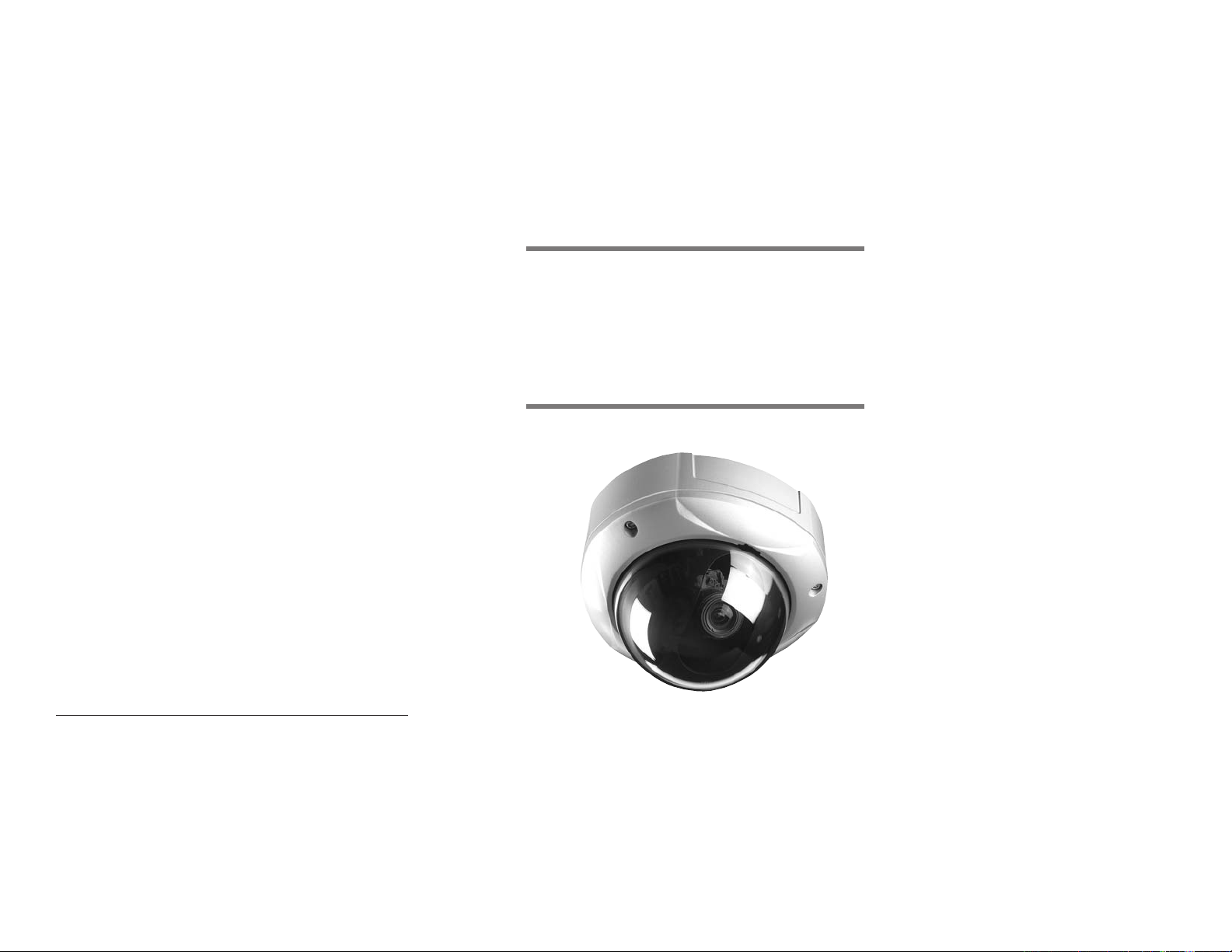
ICR540VD Day&Night Vandal Resistant Dome Camera
Copyright 2007, ICRealtime, Inc. Made in KOREA
Digital Day&Night
Vandal Resistant
Dome Camera
Operation Manual
Page 2
The lightning flash with an arrowhead symbol, within an equilateral
triangle is intended to alert the user to the presence of uninsulated
dangerous voltage within the product's enclosure that may be of
sufficient magnitude to constitute a risk of electric shock to persons.
The exclamation point within an equilateral triangle is intended to alert
the user to the presence of important operating and maintenance
(servicing) instructions in the literature accompanying the appliance.
INFORMATION - This equipment has been tested and found to comply with
limits for a Class A digital device, pursuant to part 15 of the FCC Rules & CE Rules.
These limits are designed to provide reasonable protection against harmful
interference when the equipment is operated in a commercial environment.
This equipment generates, uses, and can radiate radio frequency energy and, if
not installed and used in accordance with the instruction manual, may cause
harmful interference to radio communications.
Operation of this equipment in a residential area is likely to cause harmful
interference in which case the user will be required to correct the interference at
his own expense.
WARNING - Changes or modifications not expressly approved by the
manufacturer could void the user’s authority to operate the equipment.
CAUTION : To prevent electric shock and risk of fire hazards:
◆ Do NOT use power sources other than those specified.
◆ Do NOT expose this appliance to rain or moisture.
This installation should be made by a qualified service person and
should conform to all local codes.
1
ICR540VD - Vandal Resistant Dome Camera
Page 3

Features
Warning
Horizontal Resolution of 540 TV
Lines
Clear image quality has been achieved by
employing a SONY CCD with 410,000
(effective) pixels, which provides a
horizontal resolution of 540 TV lines.
DAY & NIGHT
This camera has a function that automatically selects the mode that is
appropriate for daytime or night-time
conditions. The COLOR mode operates in
daytime conditions to provide optimum
colors, and BW mode operates in nighttime conditions to enhance the definition
of the image.
Electronic IRIS
The electronic IRIS function enables
continuous automatic control of the
shutter between 1/60~1/120,000 seconds.
PRIVACY Function
The PRIVACY function conceals the
areas not required to appear on
the image.
High Sensitivity
The built-in high sensitivity SONY COLOR
CCD enables a clear image even in
0.3Lux(0.1Lux B/W) or as low as 0.002Lux
with SENS-UP.
DNR (Digital Noise Reduction)
The amount of low illuminance noise
has been significantly reduced, and the
signal-to-noise ratio (S/N ratio) as well as
horizontal resolution have been improved,
resulting in clear and sharp images
displayed even in low light.
Controlled by OSD Menu
The camera functions are controlled by
selecting text displayed on the monitor
screen.
Additional Functions
SENS-UP, MOTION DETECTION,
MIRROR, SHARPNESS and SYNC
(INT/LL) functions are also available.
Weather Proof (IP66)
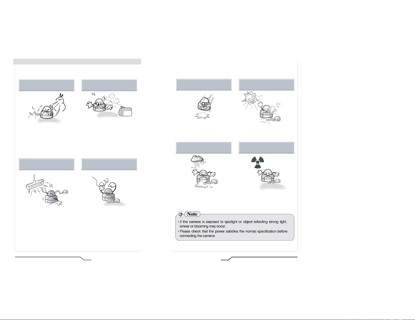
The camera requires periodic inspection.
Contact an authorised technician to carry out the inspection.
Stop using your camera when you find it malfunctioning.
If the camera emits smoke or is unusually hot for a long period,
a fire may be caused.
Do not Install the camera on a surface that can not support it.
If the camera is installed on an inappropriate surface, it may fall
and cause injury.
Do not hold plug with wet hands.
It could cause an electric shock.
Do not dis-assemble the camera.
It may result in an electric shock or other hazards.
Do not use the camera close to a gas or oil leak.
It may result in a fire or other hazards.
3 Axis built-in Vandal Resistant Dome
Housing
ICR540VD - Vandal Resistant Dome Camera
2
3
Digital Day&Night Vandal Resistant Dome Camera
Page 4

Contents
Features
Warnings and Precautions
Components
Names and Functions of Parts
Lens
OSD
VBS-EXTRA
3 Axis Bracket
SMPS
Dimensions
Installation
Cable Connections
2
3
8
9
10
10
11
11
11
11
12
13
Camera Operation
Menu
Settings
• LENS (selection)
• SHUTTER (condition and speed control)
• WHITE BALANCE control
• BLC (Back Light Compensation)
• AGC (Auto Gain Control)
• DNR (Digital Noise Reduction)
• SENS-UP
• SPECIAL
• EXIT
Troubleshooting
Specification
14
14
15
16
18
19
20
21
22
23
24
29
30
32
ICR540VD - Vandal Resistant Dome Camera
4
5
Digital Day&Night Vandal Resistant Dome Camera
Page 5
Precautions
Do not install the camera in
extreme temperature conditions.
Only use the camera under conditions
where temperatures are between
-10°C and +50°C. Be especially
careful to provide ventilation when
operating under high temperatures.
Do not install the camera under
unstable lighting conditions.
Severe lighting change or flicker can
cause the camera to work improperly.
Do not install or use the camera in an
environment where the humidity is high.
It can cause the image quality to be
poor.
Do not touch the front lens of the
camera.
This is one of the most important parts of
the camera. Be careful not to leave
fingerprints on the lens cover.
Do not drop the camera or protect
it from physical shocks.
It can cause malfunctions to occur.
Do not expose the camera to rain
or spill beverage on it.
If it gets wet, wipe it dry immediately.
Liquids can contain minerals that
corrode the electronic components.
Never keep the camera pointed
directly at strong light.
It can damage the CCD.
Do not expose the camera to
radioactivity.
If exposed to radioactivity the CCD
will fail.
6
ICR540VD - Vandal Resistant Dome Camera
7
Digital Day&Night Vandal Resistant Dome Camera
Page 6
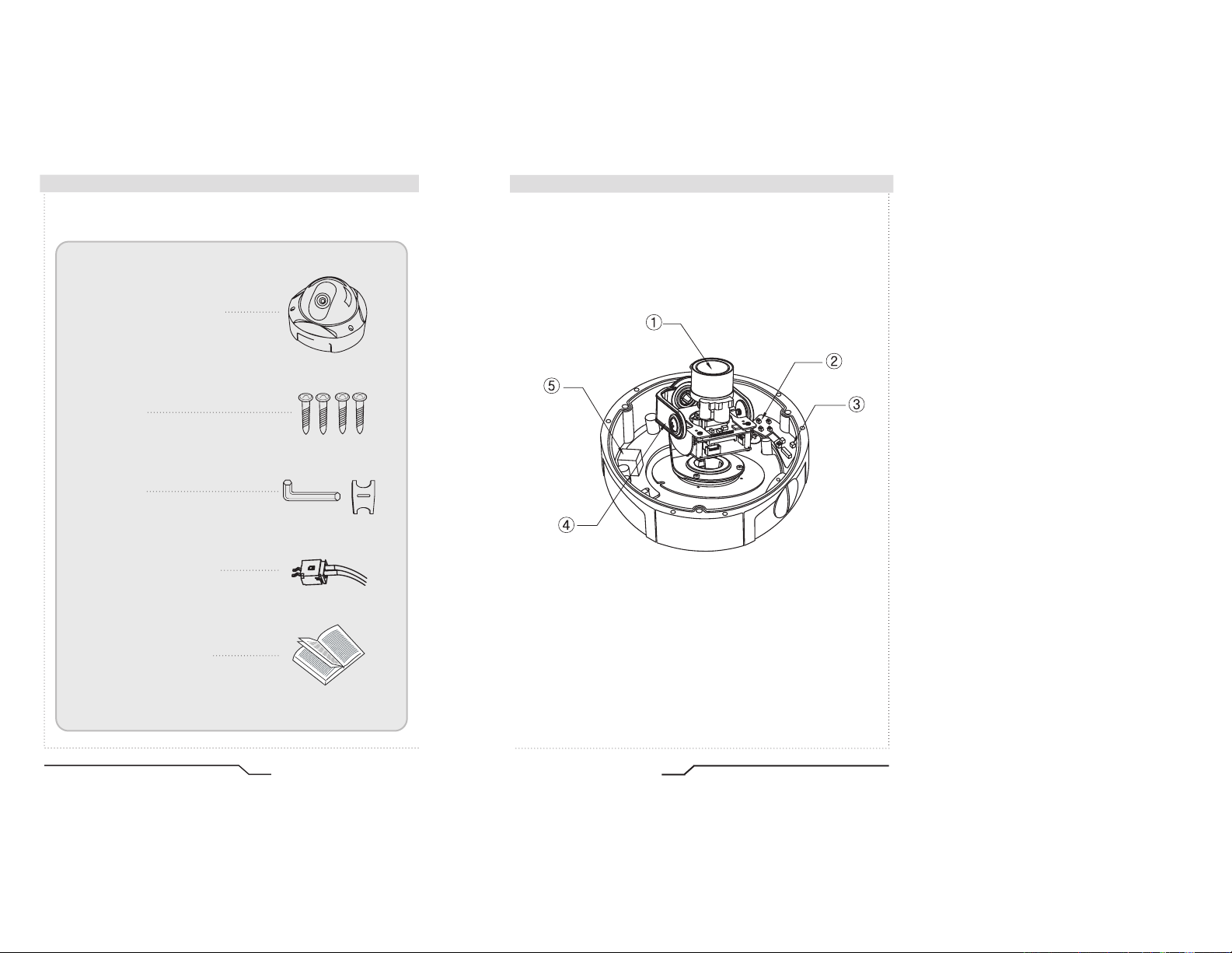
■ Components
1. COLOR DOME CAMERA
2. SCREWS
3. WRENCH
4. WIRE FOR VBS-EXTRA
Names and Functions of Parts
■
5. INSTRUCTION GUIDE
ICR540VD - Vandal Resistant Dome Camera
8
9
Digital Day&Night Vandal Resistant Dome Camera
Page 7

■ Names and Functions of Parts
42
42
LEFT
UP
RIGHT
DOWN
SET
CN1
VBS-Extra
SW5
Names and Functions of Parts
■
①
LENS : Vari-Focal DC Auto Iris Lens
(unit : mm)
②
OSD PCB
●
●
SET button : Used for the menu display. This button can be used to
confirm settings after changing the value of the selected function or
current conditions.
●
●
UP & DOWN buttons : Used for selecting items by moving the cursor
up or down on the menu screen.
③
VBS-EXTRA FOR CONNECTING TO LCD
Please use the supplied wire when connecting to LCD
VBS-EXTRA
④
3 AXIS BRACKET
Please loosen screws and fix tilted and panned position.
⑤
SMPS PCB FOR DUAL POWER
Dimensions
■
(unit : mm)
●
●
LEFT & RIGHT buttons : Used when changing item values, by moving
the cursor to the left or right on the menu screen.
ICR540VD - Vandal Resistant Dome Camera
10
11
Digital Day&Night Vandal Resistant Dome Camera
Page 8

■ Installation
RUBBER
BOTOTOM
1. Dome Base Mounting
- Open the dome cover by loosening 3 screws using special wrench
provided.
- Mount the base of camera to a sturdy surface using 4 screws (1.5
inch) and 4 premade holes on the base of the dome.
BOLT
MOUNT
BASE
HOUSING
No. 8-32
UNC
DECORATION
RING
M4*10
DOME COVER
2. Power Connect & Monitor Impedance
- DC12V/300mA regulated power supply (DC12V only)
AC24V Class 2 power supply (AC24V/DC12V)
- To avoid fire or shock hazard, must use a UL listed power supply.
- Set the monitor impedance switch to 75½. Check the impedance
switch when the screen turns blurred.
3. Camera Module Adjustment
- Loosen screws for 3-axis camera bracket and adjust the direction
and angle of camera.
- Make sure to retighten the screws for camera bracket.
- Set any function you wish to activate by using the OSD buttons.
4. Dome Cover Mounting
- Replace the dome cover to the base and tighten 3 screws.
Cable Connections ■
AC24V/DC12V
AC IN
DC IN
AC IN
DC IN
ICR540VD - Vandal Resistant Dome Camera
12
13
Digital Day&Night Vandal Resistant Dome Camera
Page 9

Camera Operation
LEFT
UP
RIGHT
DOWN
SET
CN1
VBS-Extra
SW5
Menu
SETUP menu
LENS (selection)
SHUTTER
(condition and speed control)
WHITE BALANCE control
BACKLIGHT
(Backlight Compensation)
AGC (Auto Gain Control)
DNR
(Digital Noise Reduction)
SENS-UP (Low illuminance)
SPECIAL
EXIT
•MANUAL •DC
•ESC •MANUAL •FLK
•ATW •AWC •MANUAL
•OFF •LOW •MIDDLE
•HIGH
•OFF •LOW •MIDDLE
•HIGH
•OFF •LOW •MIDDLE
•HIGH
•OFF •AUTO
•CAMERA ID •COLOR
•SYNC •
MOTION DETECTION
•PRIVACY •MIRROR
•SHARPNESS •RESET
•RETURN
Settings
Settings can be made using the 5 buttons located in the camera.
1. Press the SET button
•Settings can now be made. The SETUP menu is displayed on the monitor.
SETUP
LENSMANUAL
SHUTTERESC
WHITE BAL. ATW
BACKLIGHT OFF
AGC LOW
DNR LOW
SENS-UP OFF
SPECIAL
EXIT
2. Select a menu item from the list available by using the UP and DOWN buttons.
•The cursor can be moved up or down by using the UP and DOWN buttons.
Position the cursor to point to the function requiring adjsutment.
ICR540VD - Vandal Resistant Dome Camera
14
15
Digital Day&Night Vandal Resistant Dome Camera
Page 10

Camera Operation
SETUP
LENSDC
SHUTTER ---
WHITE BAL. ATW
BACKLIGHT OFF
SETUP
Select any function you
wish to operate by
using the UP and
DOWN buttons.
LENS MANUAL
SHUTTERESC
WHITE BAL. ATW
BACKLIGHT OFF
AGC LOW
DNR LOW
SENS-UP OFF
SPECIAL
EXIT
Modes can be changed
using the LEFT and
RIGHT buttons.
3. When the LEFT or RIGHT button is pressed, available values and modes are
displayed in order. Keep pressing the button until you get to the mode you wish to
select.
4.
Select 'EXIT' and then press the SET button to exit the set up Menu.
Note
• If appears at the mode you wish to operate, it means that there is a
sub-menu which can be selected by pressing the SET button.
• If appears at the mode item, it means that there is no mode
available to be selected.
LENS (selection)
This function is used to adjust the brightness of the screen.
1. When the SETUP menu is displayed on the screen, position the cursor to point
to 'LENS' by using the UP and DOWN buttons.
2. Select the type of the lens setting to use by pressing the LEFT or RIGHT button.
MANUAL : Manual Lens selection
DC : Auto Iris Lens selection
Note
• The brightness of the screen can be adjusted in DC mode. The brightness
can be adjusted within the range of 1 ~ 70. The optimum level of brightness
for the user can be achieved by adjustment.
• If you select the MANUAL mode, it can be adjusted in ESC mode.
3. Press the SET button if you wish to return to the previous menu
ICR540VD - Vandal Resistant Dome Camera
16
17
Digital Day&Night Vandal Resistant Dome Camera
Page 11

Camera Operation
SETUP
LENSMANUAL
SHUTTERESC
WHITE BALATW
BACKLIGHT OFF
SHUTTER (condition and speed control)
Auto or manual control can be selected.
1. When the SETUP menu is on the screen, position the cursor to point to
'SHUTTER' by using the UP and DOWN buttons.
2. Select the shutter mode by pressing the LEFT or RIGHT button.
FLK : Select 'FLK' mode when flickering occurs on the screen
ESC : Auto control of the shutter speed is enabled.
MANUAL : The shutter speed can be controlled manually.
3. Select 'MANUAL' mode for manual shutter speed adjustment.
•
4. Press the SET button when the settings are completed.
due to an imbalance between illumination and frequency.
NTSC Model:1/100, PAL Model: 1/120
When ESC mode is on, the shutter speed is controlled automatically
according to the brightness of the scene.
Selectable speeds are from ‘1/60’ to ‘1/120,000’sec (NTSC) and ‘1/50’
to ‘1/120,000’sec (PAL).
Note
• While using the internal synchronous system, if the shutter setting is on
'ESC' and the camera is directly facing bright fluorescent lights the
image on the screen can be adversely affected - therefore choose
the installation location carefully.
• When 'MANUAL' mode is on, the SENS UP function cannot be used.
WHITE BALANCE control
The screen colours can be adjusted using the WHITE BALANCE function.
1. Position the cursor to point to 'WHITE BAL' on the SETUP menu by using the
UP and DOWN buttons.
2. Select the mode you wish to adjust by pressing the LEFT or RIGHT buttons.
※Select one of the 3 modes below.
ATW(Auto Tracking White Balance) : This mode can be used within the colour
temperature range 1,800°K ~ 10,500°K (eg, fluorescent light, outdoor, sodium
vapour lamp etc.)
AWC(Auto White Balance Control) : Press the SET button while the camera
is directed at a piece of white paper to obtain the optimum state under current
illumination. If the environment, including the light source, changes the white
balance will need to be adjusted again.
MANUAL : The manual adjustment mode enables finer adjustment.
Select ATW or AWC first then change to manual adjustment mode and press
the SET button. Set the appropriate colour temperature then increase /
decrease the red and blue colour values and monitor the colour changes of
the object.
Note
• Under the following conditions the WHITE BALANCE function may not operate
properly. In such cases, please select the AWC mode.
When the object’s surroundings have a very high colour temperature
(eg, a clear sky and sunset)
When the object’s surroundings are dark
If the camera directly faces a fluorescent light or is installed in a place where
there are considerable changes in illumination, the WHITE BALANCE
function may become unstable.
ICR540VD - Vandal Resistant Dome Camera
18
19
Digital Day&Night Vandal Resistant Dome Camera
Page 12

Camera Operation
SETUP
LENS MANUAL
SHUTTERESC
WHITE BAL. ATW
BACKLIGHT OFF
AGC LOW
DNR LOW
BLC (Back Light Compensation)
When there is a strong backlight behind the object, clear images of the
background as well as the object can still be obtained by using the
BACKLIGHT function.
1. Position the cursor to point to 'BACKLIGHT' on the SETUP menu by using
the UP and DOWN buttons.
2. Select the value required by pressing the LEFT or RIGHT button.
HIGH : The gain increases from 0dB up to 42dB.
MIDDLE : The gain increases from 0dB up to 30dB.
LOW : The gain increases from 0dB up to 18dB.
OFF : BACKLIGHT function does not operate.
AGC (Auto Gain Control)
1. Position the cursor to point to 'AGC' on the SETUP menu by using the
UP and DOWN buttons.
2. Select the value required by pressing the LEFT or RIGHT button. As the
level of gain increases the screen gets brighter but the level of noise will
also increase.
HIGH
MIDDLE
LOW
: The gain
: The gain
: The gain
varies between
varies between
varies between
the range of 6dB ~ 42dB.
the range of 6dB ~ 30dB.
the range of 6dB ~ 18dB.
OFF : The gain is fixed at 6dB.
SETUP
LENSMANUAL
SHUTTERESC
WHITE BAL. ATW
BACKLIGHT OFF
AGC LOW
SENS-UP OFF
SPECIAL
EXIT
LOWDNR
ICR540VD - Vandal Resistant Dome Camera
20
21
Digital Day&Night Vandal Resistant Dome Camera
Page 13

■ Camera Operation
DNR (Digital Noise Reduction)
The level of background noise in low light decreases automatically as the
level of gain changes.
1. Position the cursor to point to 'DNR' on the SETUP menu by using the
UP and DOWN buttons.
2. Select the value required by pressing the LEFT or RIGHT button.
1. Position the arrow to point to 'SENS UP' on the SETUP menu by using the
UP and DOWN buttons.
2. Select the value required by pressing the LEFT or RIGHT button.
● AUTO : Low light level automatic mode.
● OFF : The function does not operate
.
Note
When SHUTTER is in the manual or flk mode, SENS UP does not operate.
When AGC is turned off, SENS UP does not operate.
● OFF : There is no reduction in noise level.
● LOW : There is a small reduction in noise level with almost no
● MIDDLE : The most effective mode. There is a sufficient reduction in
● HIGH : The level of noise is reduced greatly, however there is an
ghost image
noise levels without causing significant ghosting.
increase in ghosting.
.
Note
When AGC is turned off, DNR does not operate.
SENS UP (Low Illuminance)
SENS UP helps maintain a bright, clear screen image by automatically
detecting changes in the level of light in low light level conditions.
ICR540VD - Vandal Resistant Dome Camera
22
3. Press the SET button when all the settings are complete.
Note
The maximum storage magnification in low light level movement situations
can be adjusted by pressing the SET button in 'AUTO' mode.(X2~X128)
As the magnification increases the screen gets brighter; however the after
image also increases.
If storage magnification is increased while SENS UP is operational, it may
cause noise and spots may appear; this is normal.
23
Digital Day&Night Vandal Resistant Dome Camera
Page 14

Camera Operation
SPECIAL
CAMERA ID OFF
COLORON
SYNC INT
MOTION DET OFF
PRIVACY OFF
MIRROR OFF
SHARPNESS ON
RESET
RETURN
SPECIAL
1. Position the cursor to point to 'SPECIAL' on the SETUP menu by using the
UP and DOWN buttons.
2. Select the mode required by pressing the UP or DOWN button.
SPECIAL
CAMERA ID OFF
COLORON
SYNC INT
MOTION DETOFF
PRIVACYOFF
MIRROR OFF
SHARPNESS ON
RESET
RETURN
3) Press the SET button.
4) Up to 15 characters can be used for the camera ID.
Move the cursor to the letter required by using the UP and DOWN button.
CAMERA ID : If an ID is input, this camera ID appears on the monitor
and recorded footage.
1) Position the cursor to point to ‘CAMERA ID’ by using the
UP or DOWN button.
2) Select 'ON' by pressing the LEFT or RIGHT button.
Note
If 'OFF' is selected, the ID does not
•
appear on the monitor even if it has
been input.
ICR540VD - Vandal Resistant Dome Camera
24
Select an ID from A,B~Y,Z, a,b~y,z, 0,1~8,9 by using the UP, DOWN,
LEFT and RIGHT buttons.
Lock in the characters by using the SET button.
• Once locked in the cursor moves to the next space in the ID.
Repeat the above steps until the ID is complete.
Note
• If the wrong name has been input.....
Press the SET button after moving the cursor to CLR and all the letters will be
erased. If you want to correct a letter move the cursor to the arrow at the bottom
left of the screen and press 'SET'.
Position the cursor above the letter you wish to correct and then move the cursor
onto the letter you wish to choose and press the SET button.
25
Digital Day&Night Vandal Resistant Dome Camera
Page 15

Camera Operation
5) When the camera ID is complete, select a position for the name to be
displayed.
Move the cursor onto 'POS' and then press the SET button.
The ID will appear in the top left
corner.
Select the position where the ID is
to be displayed by using the 4 directional
buttons, and then press the SET button.
6)
Select 'END' and press the SET button to complete ID input.
COLOR
- AUTO : This camera has an IR Cut Filter and automatically changes
- ON : The color mode is selected by default, and the modes do not
to the appropriate mode dependant on lighting levels.
COLOR mode is selected during daylight and B/W mode at
night time.
change automatically.
Note
• When
the AGC is turned off, COLOR does not operate.
• When an infrared light is used, there may be a problem with focusing.
SYNC :
Two sychronisation modes are available, INTERNAL and
EXTERNAL LINE-LOCK. In LINE-LOCK mode, it synchronises the
video signal between cameras without a synchronous generator.
The line-lock synchronisation is only used in areas of 60Hz
(NTSC Models) / 50Hz (PAL Models).
- INT : Internal synchronisation
- LL : External line-lock synchronisation
• If ‘LL’ is selected, it can be adjusted to the desired phase.
Press the SET button.
• Adjust to the desired phase from 0 to 359.
Note
• When the mains frequency is 50Hz, the line-lock mode (NTSC Models) cannot be used.
• When the mains frequency is 60Hz, the line-lock mode (PAL Models) cannot be used.
ICR540VD - Vandal Resistant Dome Camera
26
27
Digital Day&Night Vandal Resistant Dome Camera
Page 16

Camera Operation
MOTION DETECTION:
This product has a feature that allows you to observe movements of objects
in 4 different areas on the screen, and the words 'MOTION DETECTED'
appear on the screen when movement is detected; hence a single individual
can conduct supervision efficiently. The camera detects an object's
movement by sensing disparity of outline, and level of brightness and color.
• Please press the SET button.
- OFF : MOTION DETECTION mode is cancelled.
- ON : Any motion in the selected areas is observed.
• Please select the area you wish to observe from the 4 areas in AREA
SEL mode.
• Please select ON mode for the chosen area.
• Please adjust the size of the area to be observed by using the UP,
DOWN, LEFT or RIGHT button.
• Please press the SET button to save the changes and complete the setting.
PRIVACY : This mode conceals the areas you do not wish to appear on the screen.
- OFF : Cancels the PRIVACY mode. - ON : Operates the PRIVACY mode.
• Please press the SET button.
• Please select the area you do not wish to appear from the 4 areas in
AREA SEL mode.
• Please select ON mode for the chosen area.
• Please adjust the size of the area to be concealed by using the UP, DOWN,
LEFT or RIGHT button.
MIRROR
- ON : Sets a horizontal image inversion.
- OFF : Cancels the inversion.
SHARPNESS : The outline of the video image becomes cleaner and
more distinctive as the level of SHARPNESS increases. If the level goes
up excessively, however, it may affect the video image and generate noise.
• Please press the SETUP button.
• The available range of level is 0 ~ 31.
RESET : Returns to the level which was set by the manufacturer for shipment.
RETURN : Saves the SPECIAL menu and returns to the SETUP menu.
28
ICR540VD - Vandal Resistant Dome Camera
EXIT
Saves all the setting menus and then exits.
29
Digital Day&Night Vandal Resistant Dome Camera
Page 17

Troubleshooting
If there are problems with the camera operation, check the tables below. If
the problem persists, please contact the agent who supplied the product.
Problems
Nothing appears on the
screen.
The video image is not
clear.
The screen is dark.
There is a problem with
the camera operation.
The camera surface is
too hot and black stripes
appear on the screen.
• Check the power connection.
• Check the video signal line connection.
• Make sure that the lens is clean.
Clean the lens with a clean lint free cloth or
brush.
• Adjust the contrast control on the monitor.
• Make sure that the screen is not exposed
directly to a bright light.
Re-position the camera if necessary.
• Adjust the contrast control of the monitor.
• If there is an intermediate device, set the75ohm
Hi-z correctly, and also check the connections.
• If necessary, adjust the brightness level.
• Check if an appropriate power source to
the camera complies with the manufacturer's
standard requirement, or if the voltage is
fluctuating. Check for ground loops.
Troubleshooting
Problems
The MOTION
DETECTION function is
not working.
Colors are not quite
right.
The screen is
flickering.
L/L mode isn't able to
be selected.
L/L mode is not
available
.
COLOR mode is not
working.
SENS-UP function is not
working.
Troubleshooting
• Check if 'MOTION DETECTION' mode is
turned on.
• Check the setting of the MD AREA.
• Check the 'WHITE BAL' setting.
(Please refer to page 19)
• Check if the camera is facing directly into
sunlight or fluorescent light.
• Have you connected your camera to DC power
source? Connect it to AC power source.
• Check the frequency of power supply
(60Hz for NTSC, 50Hz for PAL).
• Check if the AGC menu is set to the OFF
position.
• Check if the AGC menu is set to the OFF
position.
• Check if the SHUTTER menu is set to
MANUAL mode.
ICR540VD - Vandal Resistant Dome Camera
30
31
Digital Day&Night Vandal Resistant Dome Camera
Page 18

Specifications
Memo
ITEM
Power Source
Total Pixels
C
Effective Pixels
C
Size
D
Scanning System
s
Synchronization
y
n
c
Frequency
Resolution
Video Output
S/N (Y signal)
Min. Illumination
Color
E
L
Gain Control
E
C
White Balance
T
Electronic Shutter Speed
R
I
Sens-Up
C
A
O.S.D
L
Motion Detection
DNR
Mirror
Privacy Function
Operating Temperature / Humidity
Weight
NTSC PAL
AC24V / DC12V DC12V AC24V / DC12V DC12V
215mA(AC24V) / 250mA(DC12V)
811(H) x 508(V) 795(H) x 596(V)
768(H) x 494(V) 752(H) x 582(V)
INT/LL Selectable
0~359°(Adjustable) 0~359°(Adjustable)
Horizontal:15.734 KHz Vertical :59.94 Hz Horizontal: 15.625 KHz Vertical : 50.00 Hz
1.0Vp-p / 75 (Video 0.714Vp-p Sync 0.286Vp-p) 1.0Vp-p / 75 (Video 0.7 Vp-p Sync 0.3 Vp-p
0.3Lux / F1.2 (Color), 0.1Lux / F1.2 (B/W), 0.002Lux (Sens-up)
ATW / AWC / MANUAL (1,800°K~10,500°K)
AUTO / MANUAL (1/60~1/120,000) AUTO / MANUAL (1/50~1/120,000
OFF / LOW / MIDDLE / HIGH (Noise Reduction)
160mA
215mA(AC24V) / 250mA(DC12V)
1/ 3 inch interline transfer CCD
2:1 Interlace
INT/LL Selectable
INT
540 TV Lines
50dB (AGC Off)
ON / AUTO
OFF / LOW / MIDDLE / HIGH
OFF / AUTO
Built-in
ON / OFF (4 Programmable Zone)
Built-in (Horizontal Image Inversion)
ON / OFF (4 Programmable Zone)
-10°C ~ +50°C / 30~90% RH
1,100g
160mA
INT
)
)
ICR540VD - Vandal Resistant Dome Camera
32
 Loading...