

ICRealtime ICIP-D8330-IR, ICIP-D8320-IR, ICIP-D8123-IR, ICIP-B8310-IR, ICIP-B8121-IR User Manual
Page 1

i
Network Camera Web3.0 Operation Manual
Version 1.0.1
Page 2

ii
Table of Contents
1 Network Config ............................................................................................................................ 1
1.1 Network Connection ..................................................................................................... 1
1.2 Log in .............................................................................................................................. 1
2 Live ................................................................................................................................................ 6
2.1 Encode Setup ................................................................................................................ 6
2.2 System Menu ................................................................................................................. 7
2.3 Video Window Function Option .................................................................................. 7
2.4 Video Window Setup .................................................................................................... 8
2.4.1 Image Adjustment ..................................................................................................... 8
2.4.2 Original Size ............................................................................................................. 9
2.4.3 Full Screen ................................................................................................................ 9
2.4.4 Width and Height Ratio .......................................................................................... 10
2.4.5 Fluency Adjustment ................................................................................................ 10
2.4.6 Rules Info ............................................................................................................... 10
2.4.7 Zoom and Focus ..................................................................................................... 10
2.4.8 Fisheye/Trigger Track ............................................................................................ 10
3 PTZ Control ................................................................................................................................ 15
3.1 Scan .............................................................................................................................. 16
3.2 Preset ............................................................................................................................ 17
3.3 Tour ............................................................................................................................... 17
3.4 Pattern .......................................................................................................................... 18
3.5 Assistant ....................................................................................................................... 19
3.6 Light Wiper ................................................................................................................... 19
4 Playback ..................................................................................................................................... 20
4.1 Playback ....................................................................................................................... 20
4.1.1 Function of Play ...................................................................................................... 21
4.1.2 Playback File .......................................................................................................... 22
4.1.3 Playback Cut ........................................................................................................... 24
4.1.4 Record Type ........................................................................................................... 24
4.1.5 Progress Bar ............................................................................................................ 24
4.1.6 Assistant Function .................................................................................................. 25
4.2 Picture Playback ......................................................................................................... 25
4.2.1 Play ......................................................................................................................... 26
4.2.2 Playback File .......................................................................................................... 26
4.2.3 Snapshot Type ........................................................................................................ 28
5 Setup ........................................................................................................................................... 30
5.1 Camera ......................................................................................................................... 30
Page 3

iii
5.1.1 Conditions ............................................................................................................... 30
5.1.2 Video ...................................................................................................................... 41
5.1.3 Audio ...................................................................................................................... 53
5.2 Network ......................................................................................................................... 56
5.2.1 TCP/IP .................................................................................................................... 56
5.2.2 Connection .............................................................................................................. 58
5.2.3 PPPoE ..................................................................................................................... 60
5.2.4 DDNS ..................................................................................................................... 61
5.2.5 IP filter .................................................................................................................... 62
5.2.6 SMTP (e-mail) ..................................................................................................... 63
5.2.7 UPnP ....................................................................................................................... 64
5.2.8 SNMP ..................................................................................................................... 65
5.2.9 Bonjour ................................................................................................................... 68
5.2.10 Multicast ................................................................................................................. 68
5.2.11 4G ........................................................................................................................... 69
5.2.12 WIFI ........................................................................................................................ 71
5.2.13 802.1x ..................................................................................................................... 73
5.2.14 QoS ......................................................................................................................... 74
5.2.15 HTTPs ..................................................................................................................... 75
5.3 Event ............................................................................................................................. 85
5.3.1 Video detection ....................................................................................................... 85
5.3.2 Audio Detection ...................................................................................................... 92
5.3.3 Smart Plan ............................................................................................................... 94
5.3.4 Intelligence Behavior Analytics ............................................................................. 94
5.3.5 Face Detection ...................................................................................................... 102
5.3.6 People Counting ................................................................................................... 104
5.3.7 Heat Map .............................................................................................................. 106
5.3.8 Alarm .................................................................................................................... 109
5.3.9 Abnormity ............................................................................................................. 113
5.4 Storage Management ............................................................................................... 116
5.4.1 Schedule ................................................................................................................ 116
5.4.2 Destination ............................................................................................................ 120
5.4.3 Record control ...................................................................................................... 122
5.5 System ........................................................................................................................ 123
5.5.1 General .................................................................................................................. 123
5.5.2 Account ................................................................................................................. 126
5.5.3 PTZ ....................................................................................................................... 129
5.5.4 Default .................................................................................................................. 130
5.5.5 Import/Export ....................................................................................................... 131
Page 4

iv
5.5.6 Remote control ........................................................................................................ 131
5.5.6 Auto Maintenance ................................................................................................. 132
5.5.7 Upgrade ................................................................................................................ 133
5.6 Information ................................................................................................................. 133
5.6.1 Version .................................................................................................................. 133
5.6.2 Log ........................................................................................................................ 134
5.6.3 Online User ........................................................................................................... 134
6 Alarm ......................................................................................................................................... 136
7 Log out ...................................................................................................................................... 138
Page 5

v
Important
The following functions are for reference only. Some series products may not
support all the functions listed below.
Page 6
1
1 Network Config
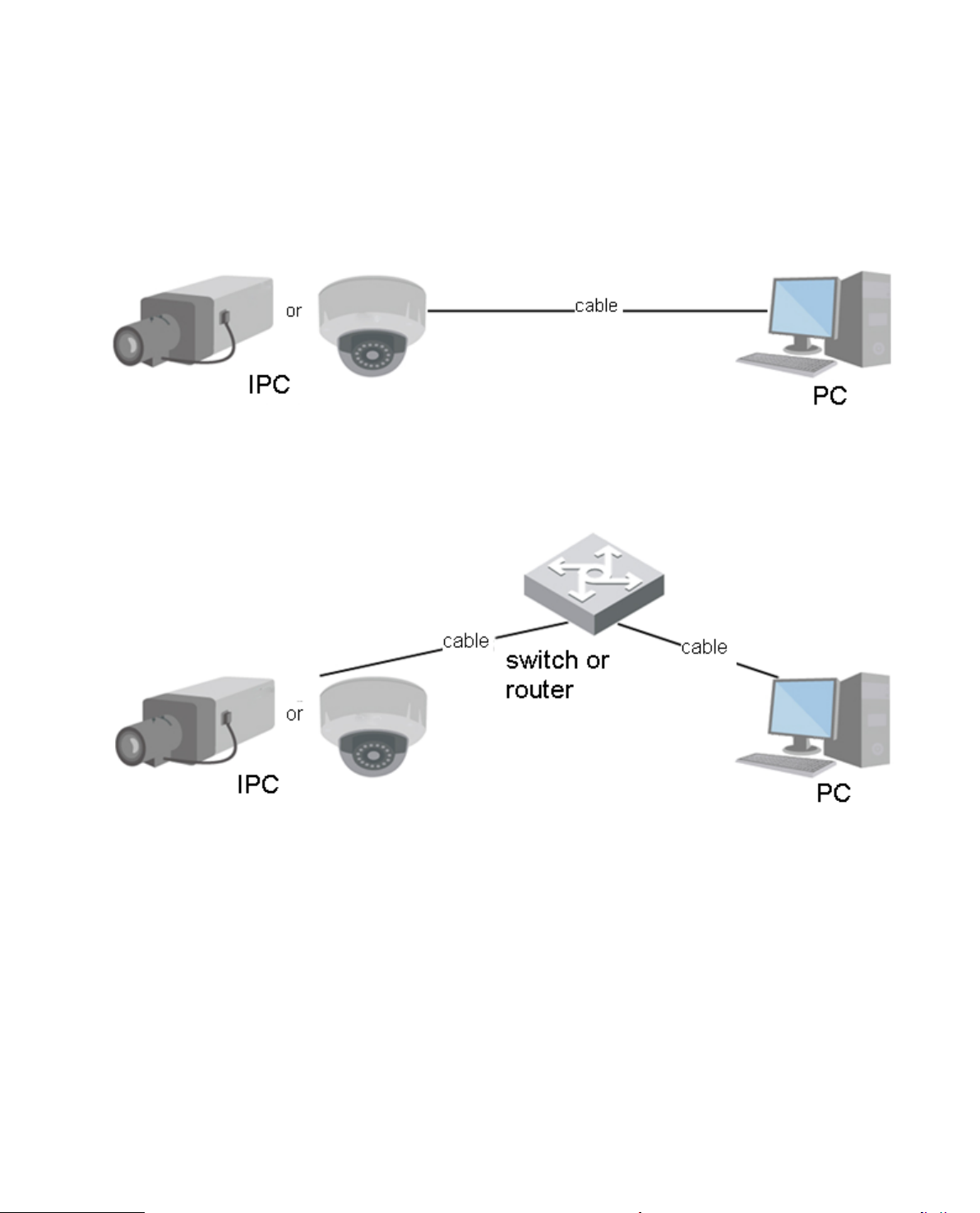
1.1 Network Connection
Network camera and PC c onnection mainly has two ways, see Figure 1- 1 and Figure 1-2.
Figure 1- 1
Figure 1-2
Before you access networ k camera via the Internet, you need to have its IP address. User can use
Config Tool to search IP of the net work camera. Please refer t o Config Tool manual.
1.2 Log in
It needs to install WEB plu g-in when you use WEB client for the first time, the exact operation st eps are
shown as follows:
Open IE and input networ k camera address in the address bar . (The factory default IP address is
192.168.1.108).
Page 7
2
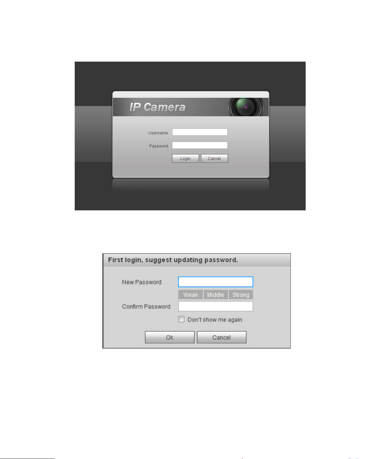
After successful connection, t he login interface is shown as in Figur e 1-3; input your user name and
password. Default factory usernam e is admin and password is admin.
Figure 1-3
The system will display “Update Password” prompt box for your firs t logi n, u ser s need to modify the
password and save it properly.
Figure 1-4
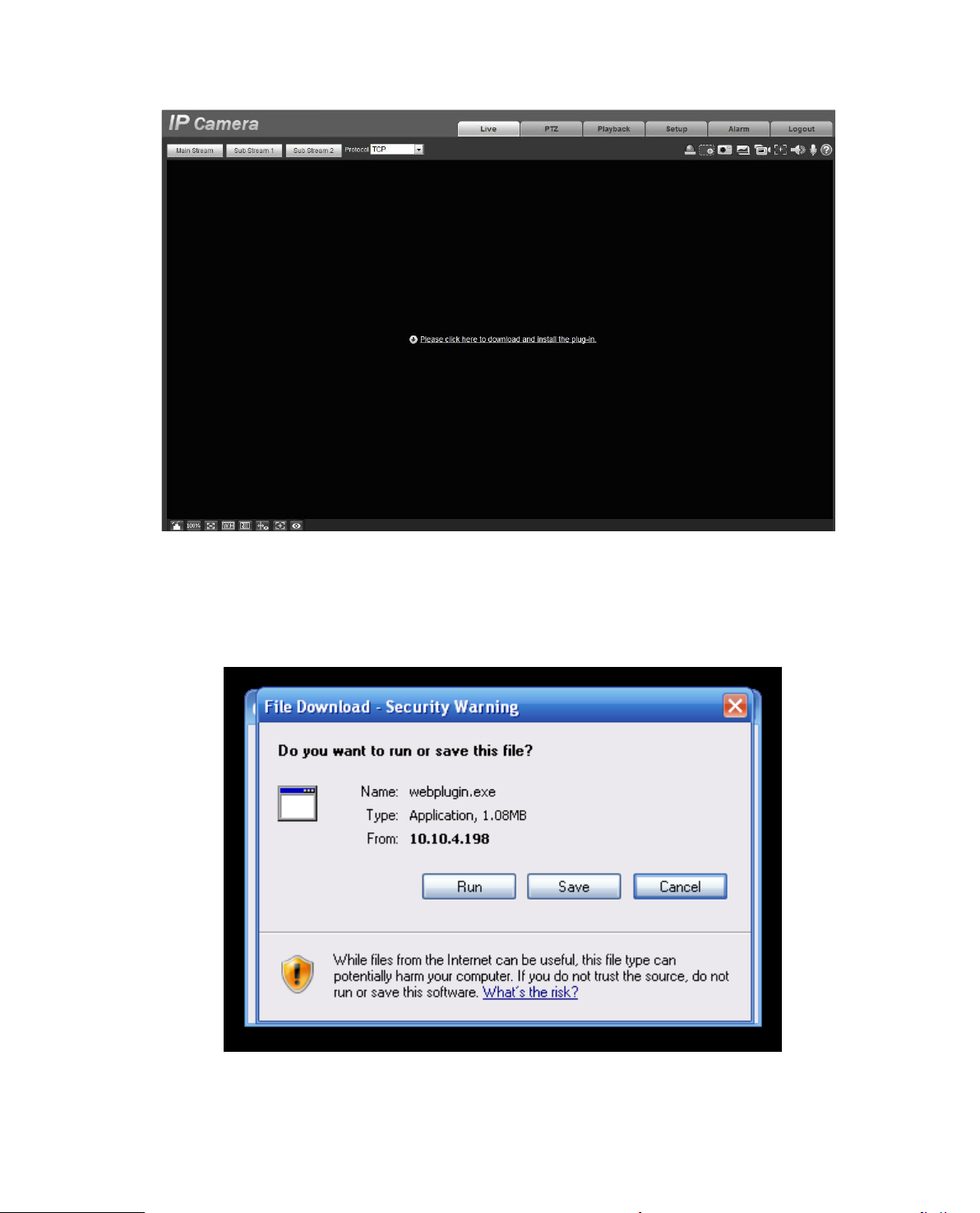
After successful login, you may see the interface s hown as in Figure 1-5.
Page 8
3
Figure 1-5
Click on “Please click here to download and install the pl ug-in”. The system pops up warning information
to ask you whether run or save t his pl ug-in. See Figure 1-6.
Figure 1-6
Page 9
4
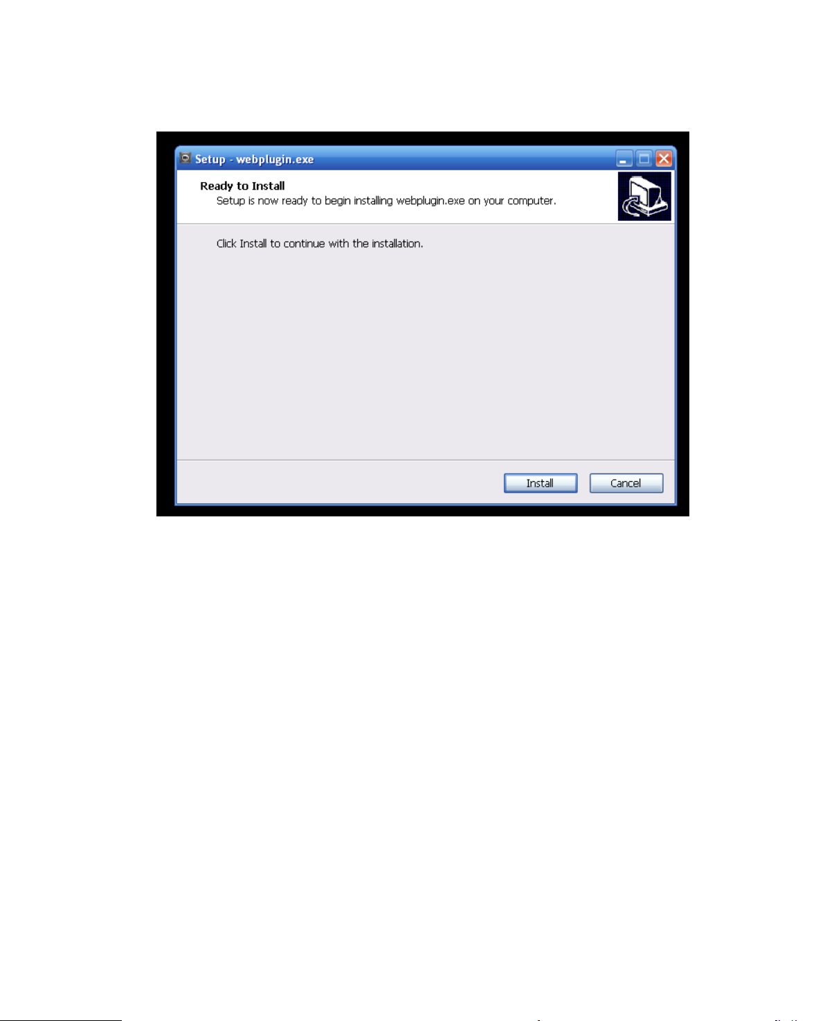
You must either run or save the file to local and install it. Follow t he f ol low i ng steps. Click on run, y ou
will see Figure 1-7and Figur e 1-8.
Figure 1-7
Page 10
5
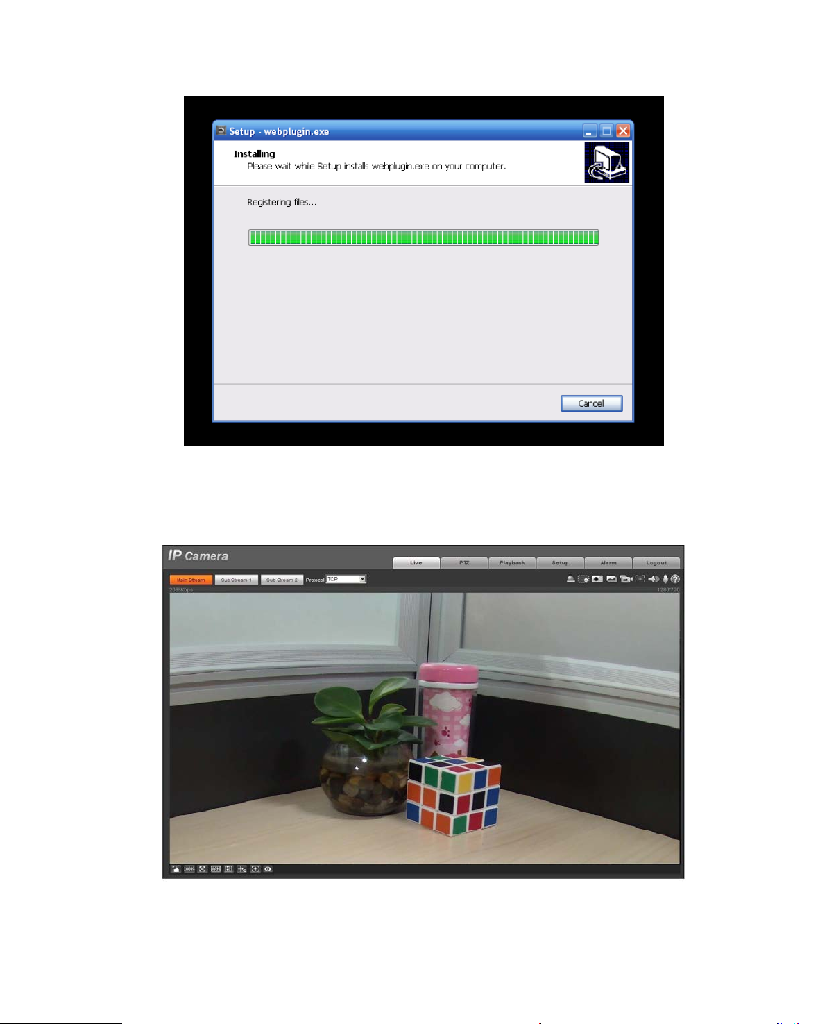
Figure 1-8
When plug-in installation complet es , t he installation page closes automatically. The web-end will refresh
automatically, and then y ou can view video captured by t he camera.
Figure 1-9
Page 11
6
2 3 1
4
2 Live
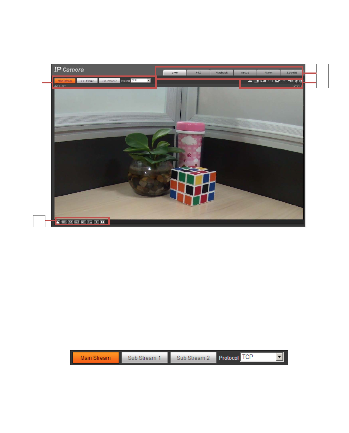
After you logged in, you c an s ee t he live monitor window. See Figure 2-1.
Figure 2-1
There are four sections:
Section 1: Encode setup bar
Section 2: System menu
Section 3: Window function option bar
Section 4: Window adjust bar
2.1 Encode Setup
Note: Some series don’t suppor t sub stream 2.
The encode setup interfac e is shown as in Figure 2-2.
Figure 2-2
Please refer to the following sheet for detailed information.
Page 12
7
Click it to enable main strea m v ideo monitoring and click again
to disable it. Generally for storage and monitor.
Click it to enable Sub Stream 1 v id eo monitoring and click again
substitutes main strea m for monitoring.
Click it to enable Sub Stre am 2 v ideo monitoring and click again
substitutes main strea m for monitoring.
You can select stream media prot ocol from the dropdown l ist.
There are three options: TCP/UDP/Multicast
It shows if there is any alarm outp ut , status description is as
Click on the button to force alarm to be on or off.
1 2 3 4 5 6 7 8 9
Parameter Function
Main stream
Sub Stream 1
Sub Stream 2
Protocol
to disable it. When network bandwidth is insufficient, it
to disable it. When network bandw idth is insufficient, it
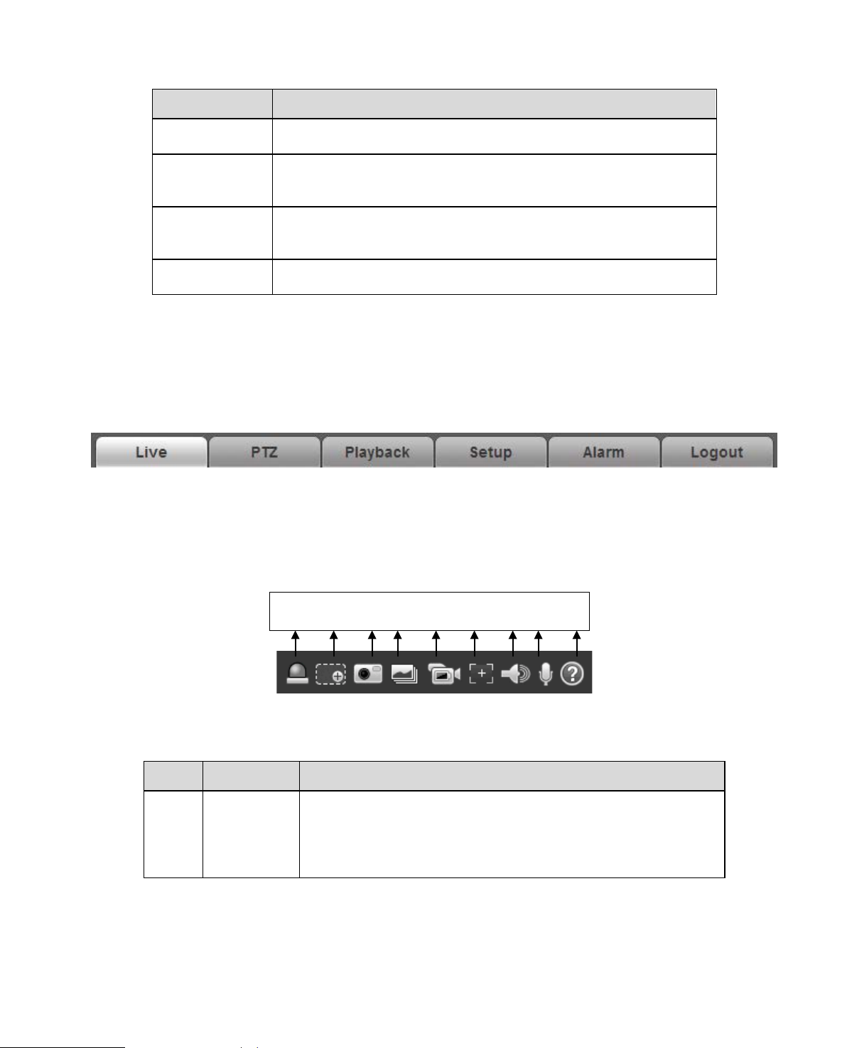
2.2 System Menu
System menu is shown as in Figure 2-3.
Please refer to chapter 2 Live, chapter 3 PTZ, ch apter 4 Playback, chapter 5 Setup, chapter 6 Alarm,
chapter 7 Log out for detailed information.
Figure 2-3
2.3 Video Window Function Opti on
The interface is shown as below . See Figure 2-4.
Figure 2-4
Please refer to the following sheet for detailed information.
SN Parameter Function
1 Relay-out
follows:
Red: means there is alarm output.
Grey: means alarm is over.
Page 13
8
When the video is in the original status, click it you can
zoom in/out the video size.
Click on the button to snapshot, save picture to path in Ch.
Click it to take snapshot upon t he video at the frequency of
5.1.2.5.
Turn on or off audio when y ou ar e mo nitoring.
2
3 Snapshot
4
5 Record
6 Easy focus
7 Audio
Digital
Zoom
Triple
snapshot
select any zone to zoom in. I n t he non-original status,
you can drag the zoom-in z one in specified range. Right
click mouse to restore previous status.
Click it; you can use the middle button of the mouse to
5.1.2.5.
one picture per second. All i ma ges ar e saved to path in Ch
Click it to record the video. All v ide os ar e saved to path in
Chapter 5.1.2.5.
Click it, you can see t her e are two parameters on the preview
video:AF Peak and AF Max.
AF Peak: It is to display the video definition during the focus
process.
AF Max: It is the most suitable value for the video definition.
The close the AF Peak and AF Ma x is, the better the focus
effect is.
8 Talk Click it to start or end bidirectional talk.
9 Help Click it to open help file.
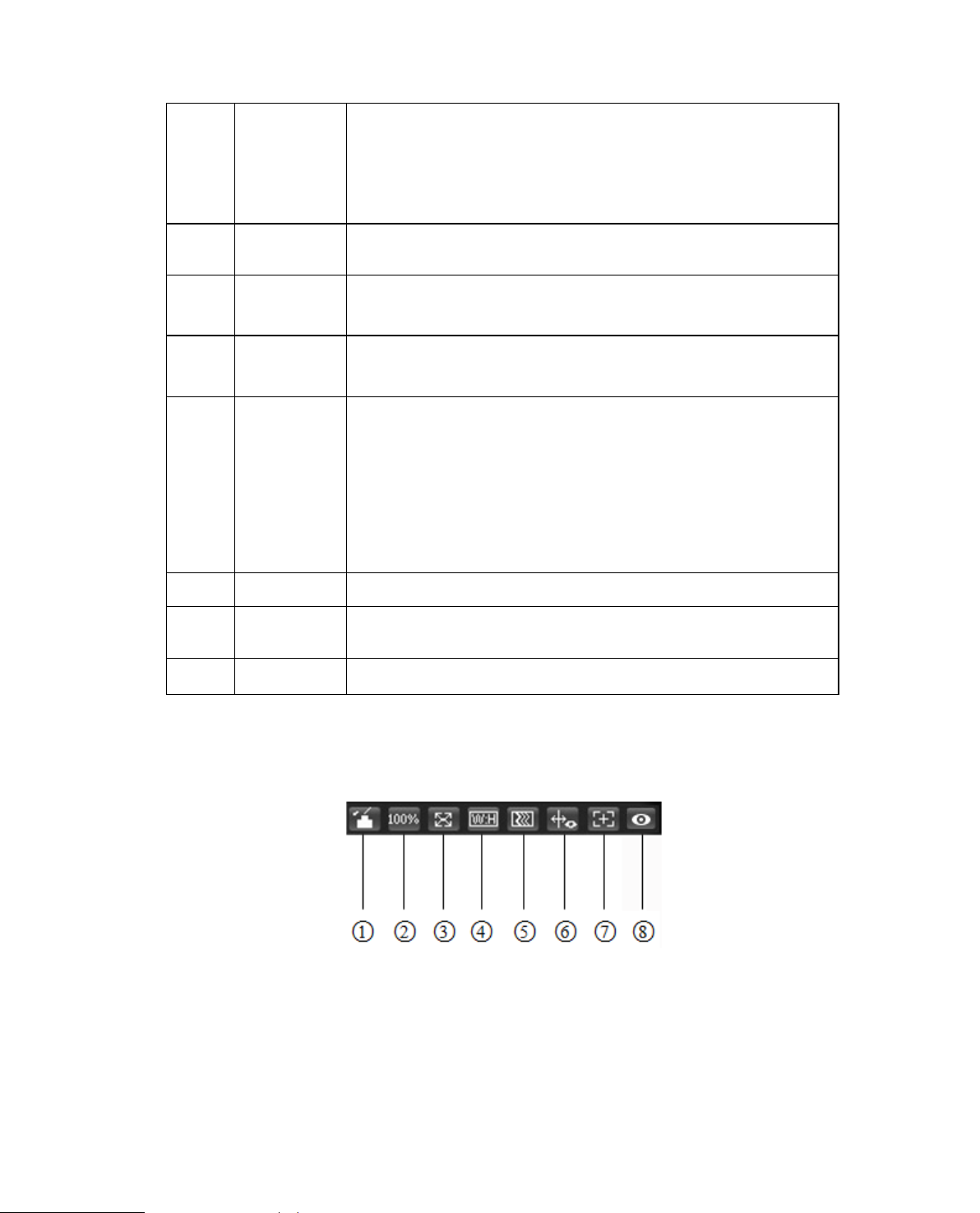
2.4 Video Window Setup
The interface is shown as in Figure 2-5.
2.4.1 Image Adjustment
See Figure 2-6 for image adjust ment.
Figure 2-5
Page 14
9
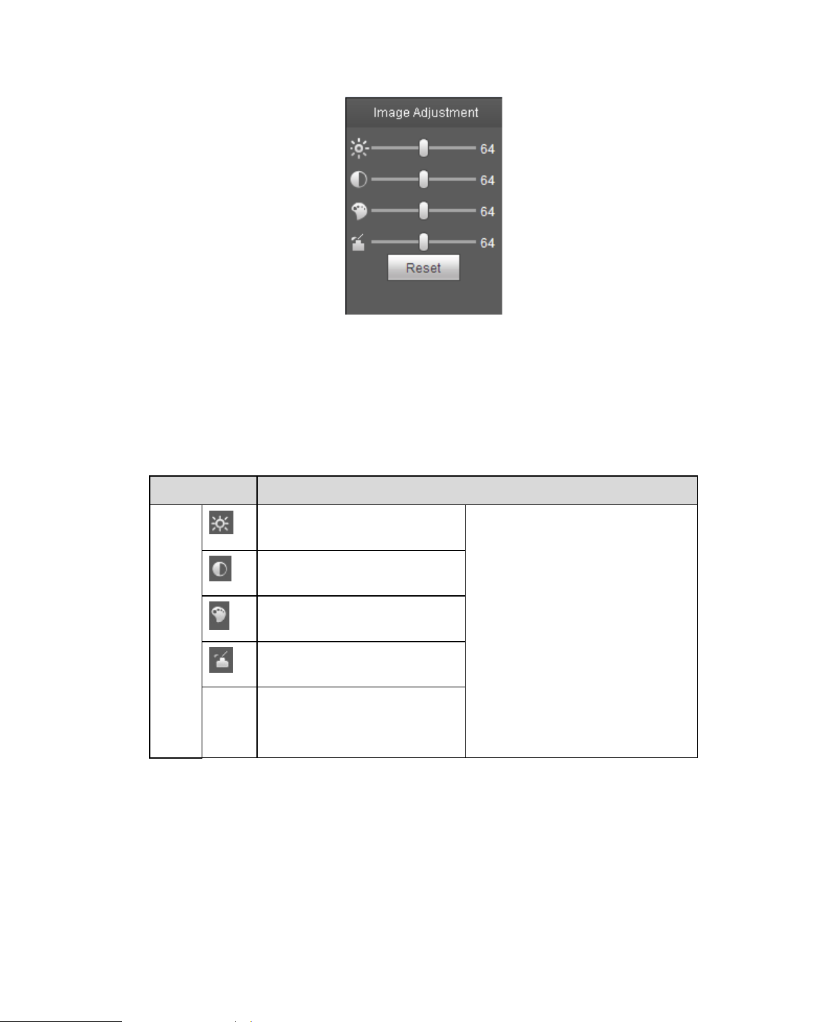
Figure 2-6
Click this button to display/hide image control interface. Click it to open picture set up int erface. This
interface is on the top right pane.
Please refer to the following sheet for detailed information.
Parameter Function
Video
setup
Reset
It is to adjust monitor video
brightness.
It is to adjust monitor video
contrastness.
It is to adjust monitor video
hue.
It is to adjust monitor video
saturation.
Restore brightness,
contrastness saturation and
hue to system default setup.
Note:
All the operations here apply
to WEB end only.
Please go to Setup-
>Camera->Conditions to
adjust corresponding items.
2.4.2 Original Size
Click this button to go to original size. It is to display the actua l siz e of t he video stream. It depends on
the resolution of the bit stream.
2.4.3 Full Screen
Click it to go to full-screen mod e. Double click the mouse or clic k the Es c button to exit the full screen.
Page 15
10
2.4.4 Width and Height Ratio
Click it to restore original ratio or suitable window.
2.4.5 Fluency Adjustment
There are three levels of fluency for you to select (Realtime, Normal, and Fluency). The default is
normal.
2.4.6 Rules Info
Click the button, preview i ma ge w i ll d isplay intelligent rules a fter enabling; it is “enable” by defa ult .
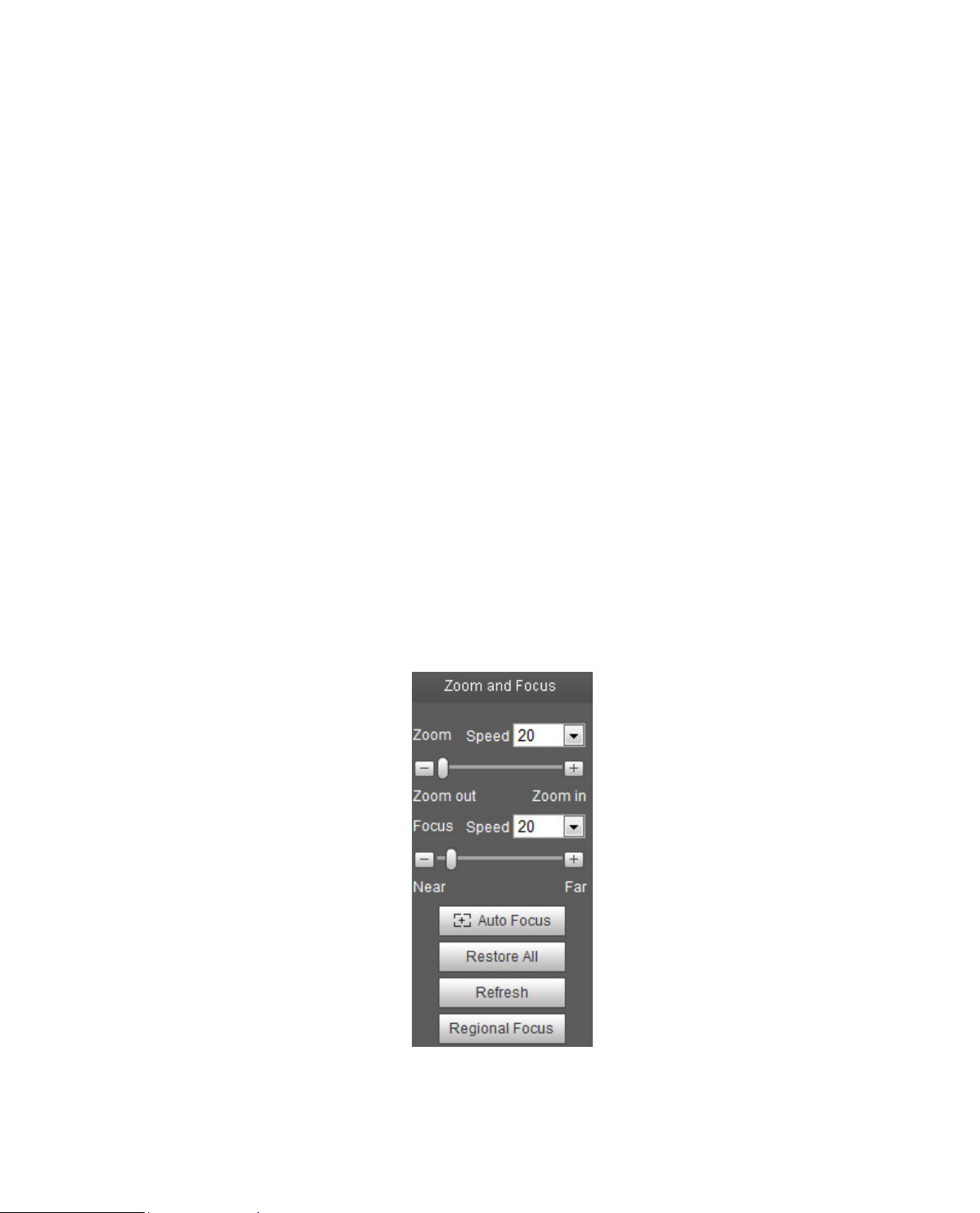
2.4.7 Zoom and Focus
Click this button and the focus z ooming interface appears on the right of preview interface, as s hown in
Figure 2-7, click left mouse button to adjust focus zooming configuration.
Note:
· The product series which support motorized zoom, synchronous focus and back focus have this
button.
· Auto-focus after zoom and focus adjustment.
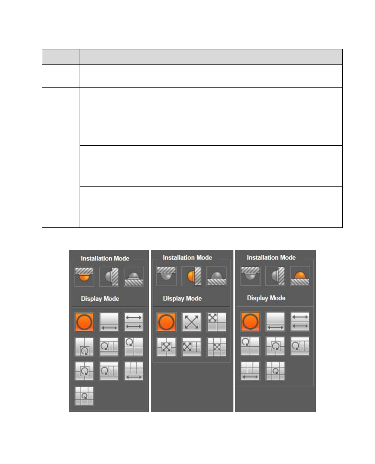
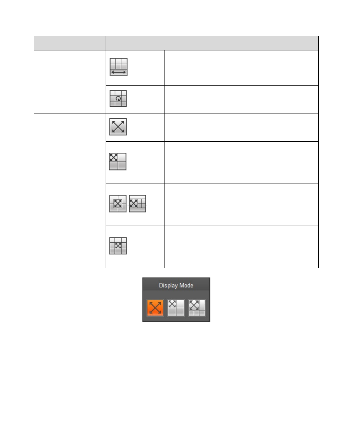
2.4.8 Fisheye/Trigger Track
Click the button, installation mode and display mode inter face will show up on the right of the pr eview
interface, see Figure 2-8 and Figure 2-9, single click t o sw it ch di fferent installation mode a nd display
mode, or different display mo des, it is enabled by default.
Note:
It is only supported by some models.
Figure 2-7
Page 16
11
Please reset when the image adjustment is not clear or operating zoom focus many
drag slider of lens and zoom focus after hardware zoom
t and use the mouse to select a zone, then the device can auto focus within the
Parameter Function
Zoom
Focus
Autofocus
Reset All
Refresh
Regional
Focus
Adjust the focal length of the lens by clicking or long pressing “ + ” “-”buttons.
Step length is used to adjust t he len gt h of one step with one click.
Adjust the sharpness of the lens by clicking or long pressing“+”、“-” buttons.
Step length is used to adjust t he len gt h of one step with one click.
Click to adjust the image definition automatically.
Note:
Other lens operations are not all ow ed during the process of auto-focus.
Reset the lens to zero position to e li m inate the accumulativ e er r or of lens.
Note:
times.
Synchronize the location of
focusing.
Click i
specific region.
In-ceiling Mount Wall Mount Ground Mount
Page 17
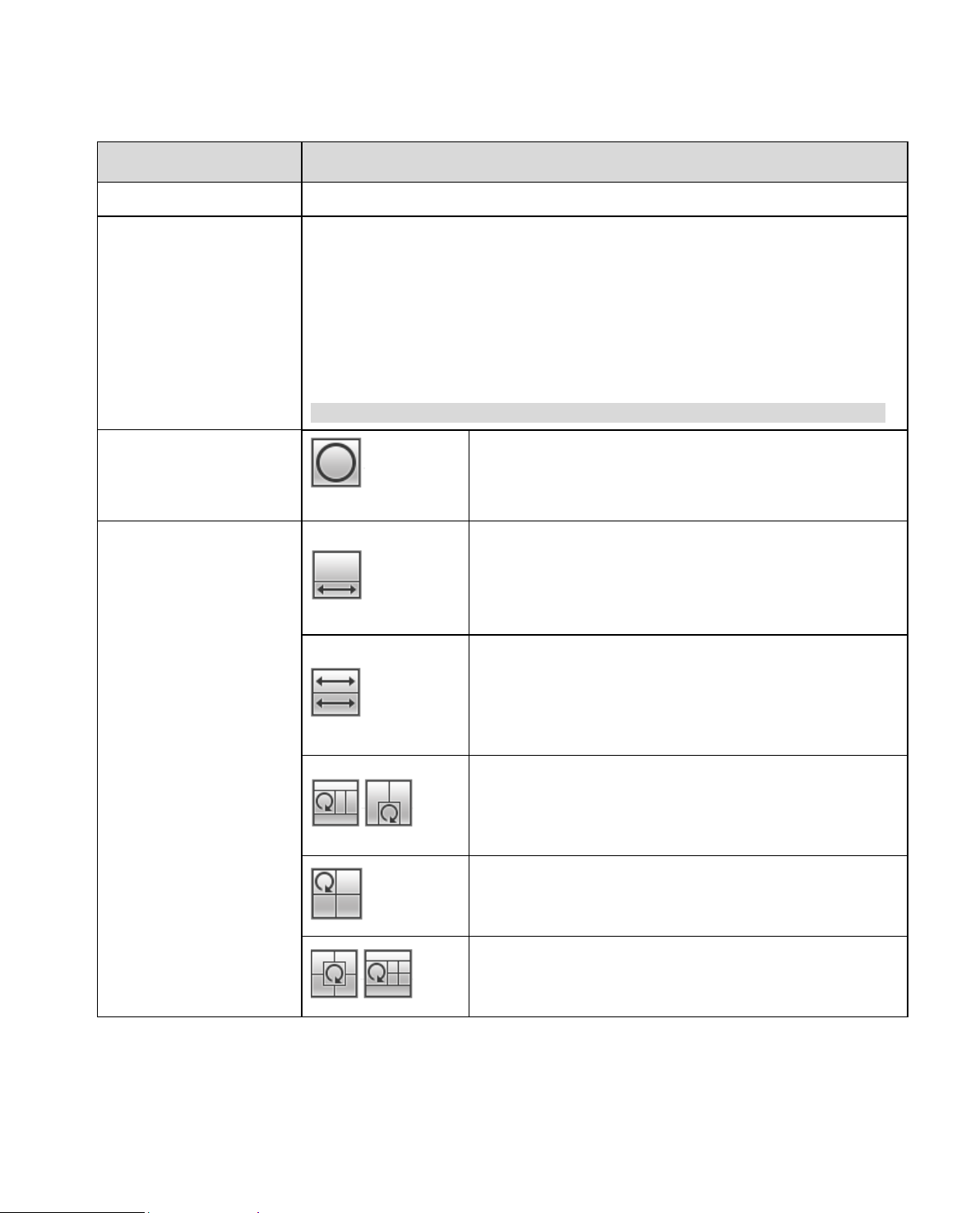
12
It represents the display mode of the current image (default supports original
image mode), the display modes may be different according to different
and the subbox in the
expanded rectangular panorama support zoom and
movement, for the expanded rectangular panorama
Two related 180° expanded rectangular pictures, two
subwindows form 360° panorama anytime, which is
also called “dual panorama”. Two expanded
rectangular pictures both support left and right
ement starting point, which are also linked by
eachother.
Original image + 2 independent sub images, both the
sub image and the subbox in the original image
support zoom and movement. The original image also
ation (no such
display mode for ground installation).
Original image + 2 independent sub images, both the
sub image and the subbox in the original image
support zoom and movement. The original image also
supports changing starting point by rotation
Original image + 4 independent sub images, both the
sub image and the subbox in the original image
support zoom and movement. The original image also
supports changing starting point by rotation
Figure 2-8
parameter Note
Installation Mode Three modes which are c eiling mount, wall mount and grou nd mount.
installation modes. It is shown as fo l lows:
Ceiling: 1P+1、2P、1+2、1+3、1+4、1P+6、1+8。
Display Mode
Wall: 1P、1P+3、1P+4、1P+8。
Ground: 1P+1、2P、1+3、1+4、1P+6、1+8。
Note:
The default displays original image mode when switc hin g installation mode.
In-ceiling/Wall/Ground
In-ceiling/Ground
image
1P+1
2P
1+3
Original
1+2
It menas the original image without de-warpping
360°expanded rectangular panorama + independent
sub image, the sub image
also supports left and righ t starting point movement.
mov
supports changing starting point by rot
1+4
Page 18
13
360°expanded rectangular panorama +6 independent
sub image, both the sub image and the subbox in the
expanded rectangular panorama support zoom and
movement, for the expanded rectangular panorama
also supports left and righ t starting point movement.
Original image + 8 independent sub images, both the
sub image and the subbox in the original image
support zoom and movement. The original image also
supports changing starting point by rotation
expanded rectangular
panorama, which supports up and down movement
180° expanded rectangular panorama+3 independent
sub images, both the sub images and the sub box in
the expanded rectangular panorama support zoom
and movement, expanded rectangular panorama
angle of view.
180° expanded rectangular panorama+4 independent
sub images, both the sub images and the sub box in
the expanded rectangular panorama support zoom
and movement, expanded rectangular panorama
nd down movement and changes vertical
angle of view.
180° expanded rectangular panorama+8 independent
sub images, both the sub images and the sub box in
the expanded rectangular panorama support zoom
and movement, expanded rectangular panorama
orts up and down movement and changes vertical
angle of view.
parameter Note
1P+6
1+8
From left to right 180°
Wall
1P
1P+3
1P+8
1P+4
and changes vertical angle of view.
supports up and down movement and changes vertical
supports up a
supp
Enable the trigger track on t he interface of tripwire or intrusi on, and draw the rule of tripwire or intr usion,
the scene of trigger track window will change according to the moving object when it t r iggers rule alarm
until the moving object dis appears from the view range of the camera. Please refer to “5.3. 4 IVS” for
more details about the rul es dr awing and parameter config o f tr ipw ire and intrusion.
Trigger track includes thr ee modes which are 1P, 1P+3 and 1P+5.
Figure 2-9
Page 19
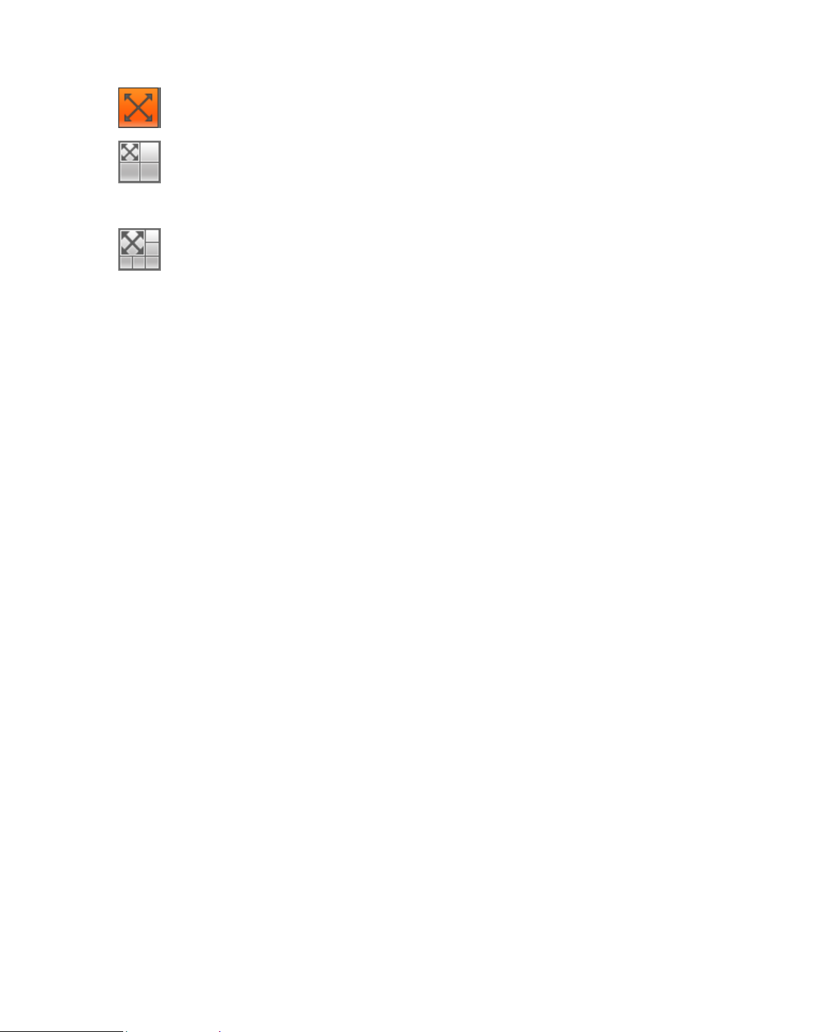
14
1P: Original picture
three trigger track window s on t he or iginal picture.
five trigger track windows on t he or iginal picture.
1P+3: Original picture and three trigger track window s, it can adj ust the location and size of
1P+5: Original picture and five trigger track window s, it c an adj ust the location and size of
Page 20
15
PTZ supports eight directions: left/right/up/down/upper left/upper
right/bottom left/bottom right.
It controls rotation speed. The longer the step length, the higher the speed.
Step length control PTZ, zoom, focus and iris.
Use mouse to draw a box in monitoring video, PTZ will rotate and focus to
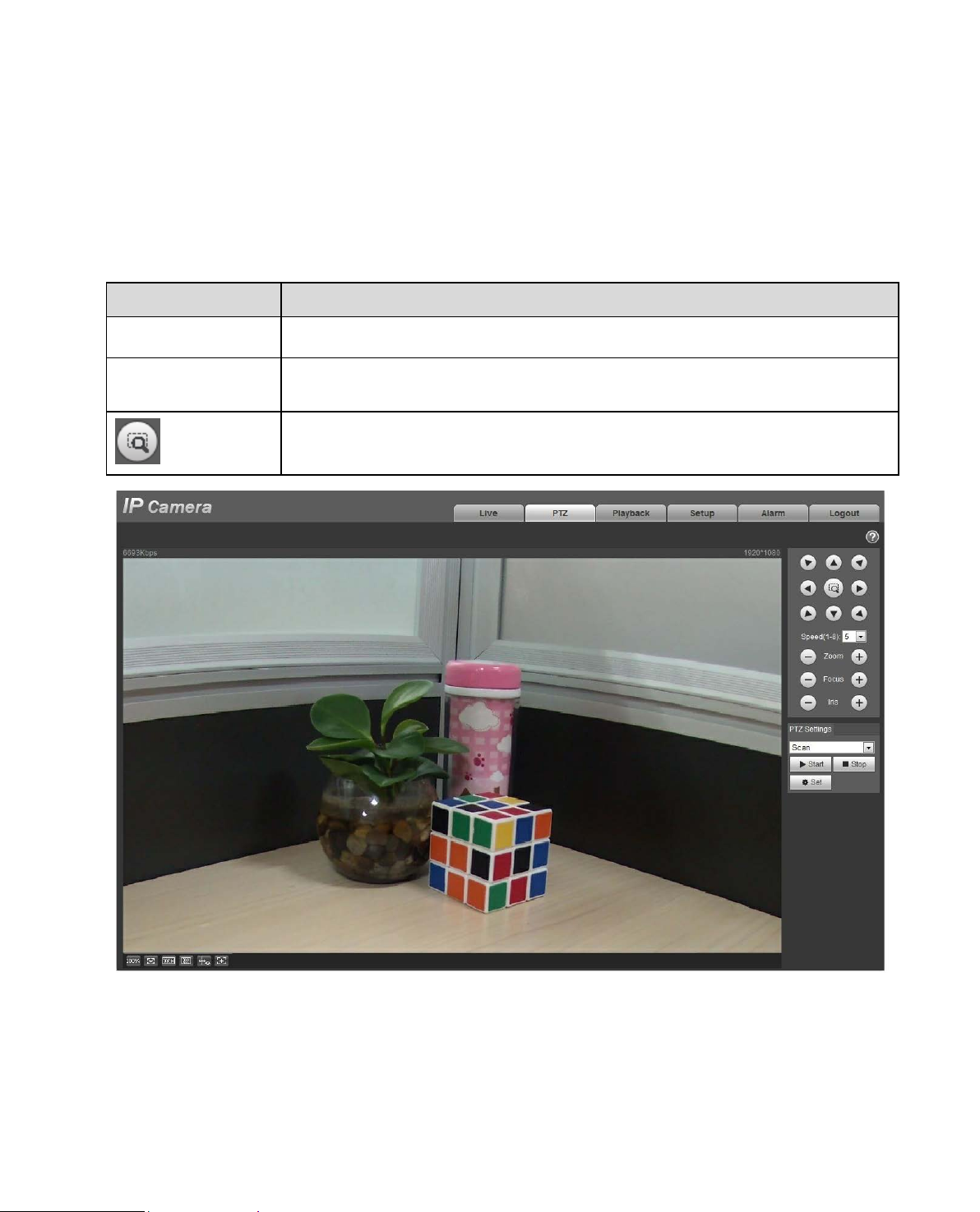
3 PTZ Control
Here you can view direction keys, speed, zoom, focus, iris, preset, tour, pan, scan, pattern, aux on, off
and PTZ setup button. See Figure 3-1.
Note:
Before PTZ operation, please make sure you have properly set PTZ protocol. (Please refer to Ch. 5.5.3).
Currently only IPC-HFXX XX series and –PT series products c an s upport PTZ function.
Parameter Note
PTZ direction
Speed
Quick Position
quickly positioning.
Figure 3-1
Page 21
16
Figure 3-2
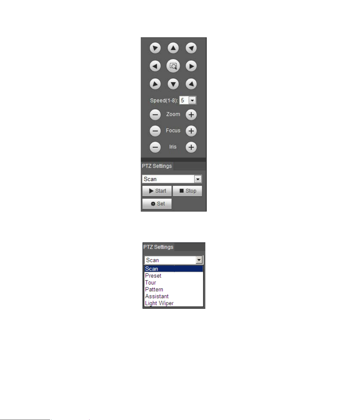
PTZ setting interface is shown as in Figure 3-3.
Here you can set scan, preset, t our , pat t er n, assistant function and light and wiper plus view coordinate.
Figure 3-3
3.1 Scan
Scan interface is shown in Figure 3-4.
Page 22
17
Steps to scan are:
Figure 3-4
Step 1. Click on Set butt on, display
Step 2. Move v ia direct ion key to select left, click on S et Lef t to set left border of camera
Step 3. Move v ia direct ion key to select right, click on Set R ight to set right border of camera.
Step 4. Complete s can path setup.
icon.
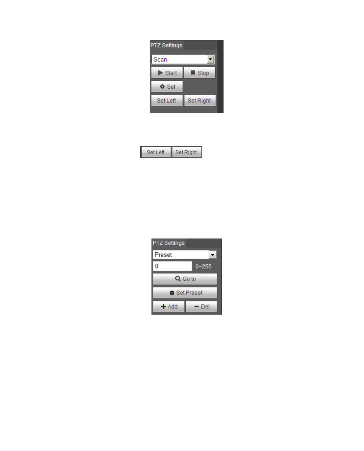
3.2 Preset
Preset interface is shown in Figure 3-5.
Figure 3-5
Steps to preset are:
Step 1. In preset box, in put pr eset value.
Step 2. Click on Go t o, cam er a r otates to preset position.
Step 3. Use direct ion key to rotate camera, and in pres et box input preset value.
Step 4. Click on Add t o add a pr eset. Range of preset relates t o PTZ protocol.
3.3 Tour
Page 23
18
Tour interface is shown in Fig ur e 3-6.
Figure 3-6
Steps to tour are:
Step 1. In tour box, input t our pat h value.
Step 2. Click on Add. Range of tour relates to PTZ pr ot ocol.
Step 3. In preset box, input preset value.
Step 4. Click on Add as to add a preset in this tour. If clic k on Del, it deletes this preset in tour.
Note:
You can add more than one preset here, or delete more than on e preset.
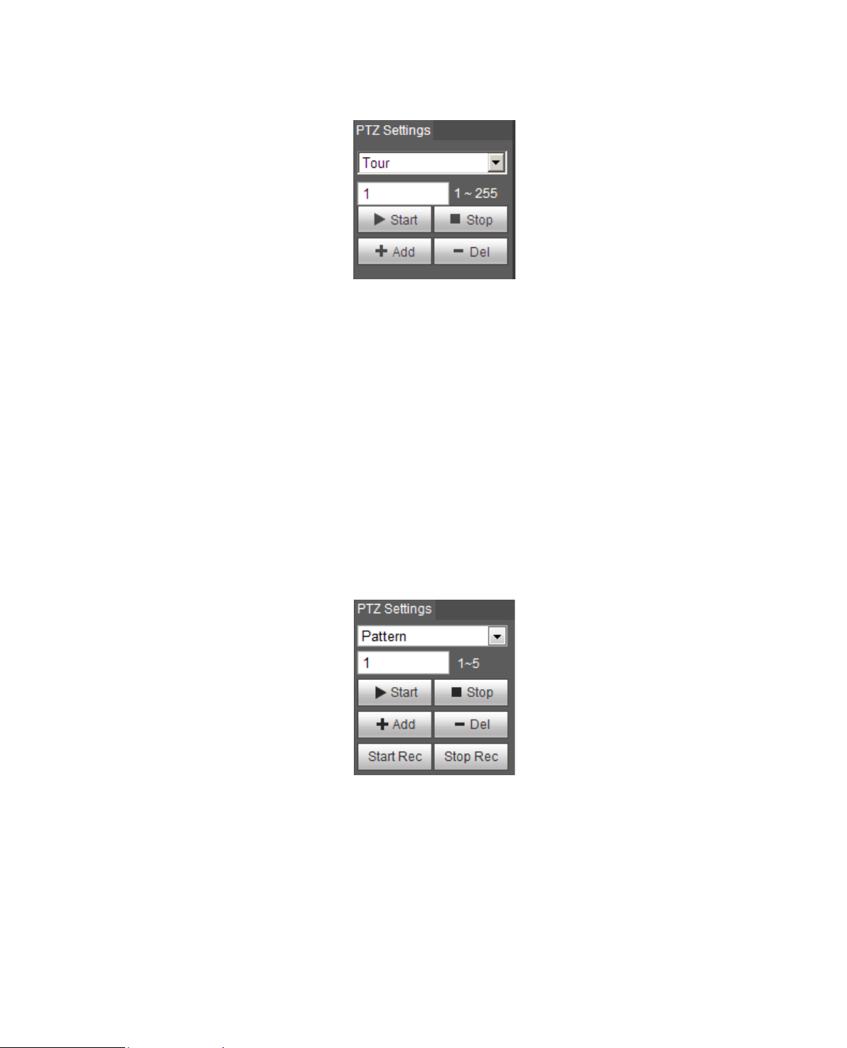
3.4 Pattern
Pattern interface is shown in Fi gure 3-7.
Figure 3-7
Steps to set pattern are shown as f ol low s:
Step 1
Input pattern serial numbe r value in the box, click “Add” and it will display “Start Rec” and “Stop R ec” .
Step 2
Click “Start Rec” to impleme nt a ser ie s of o per ations such as zoom, focus, iris, direction and so on.
Step 3
Page 24
19
Click “Stop Rec” to compl et e t he set ting of a pattern path.
Step 4
Click “Start” and it will star t pattern according to the patt er n spot which has been set; click “Stop” and
the pattern ends.
3.5 Assistant
Assistant interface is sho w n in Figure 3-8.
Figure 3-8
Steps to assistant are:
Step 1. In assistant box i nput assistant value.
Step 2. Click on Aux On to turn on aux function.
Clic k o n Aux off to turn off aux function.
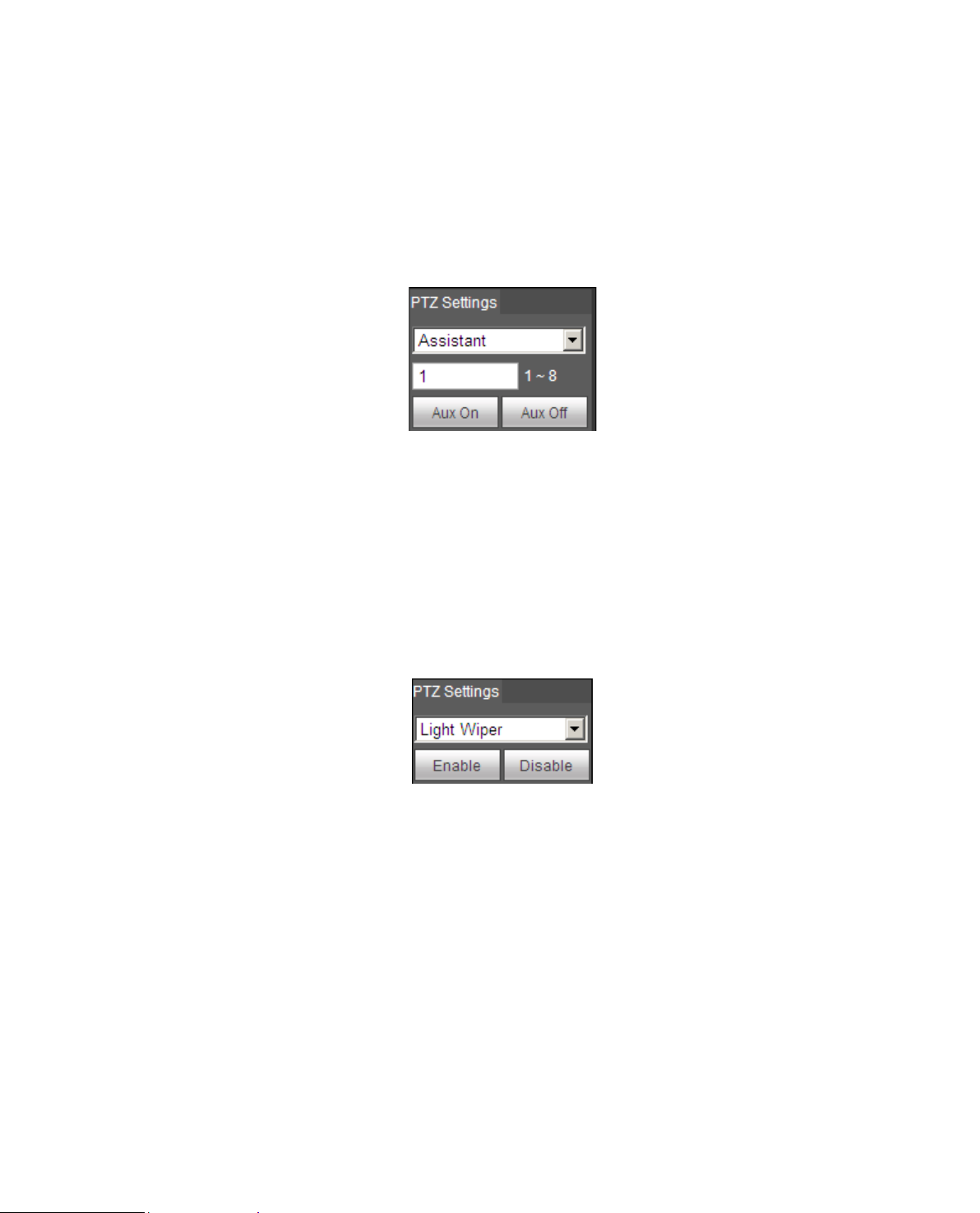
3.6 Light Wiper
Light wiper interface is shown in Figure 3-9.
Figure 3-9
Steps to light wiper are:
Click on Enable to enable light wiper function.
Click on Disable to disable light wiper function.
Page 25
20
2
3 4 1 6 5
4 Playback
Web client playback supports video pl ayback and picture playbac k.
Note:
Before playback, user sha ll set storage management as in Ch. 5.4.
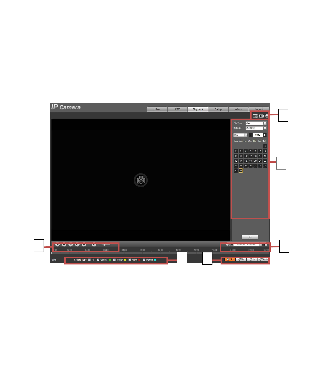
4.1 Playback
The playback interface is shown as in Figure 4-.
Figure 4-1
There are four sections:
Section 1: Function of play
Section 2: Playback file
Section 3: Play time cut
Section 4: Record type
Section 5: Progress bar
Section 6: Assistant function
Page 26
21
When you see this button, it means pause or not played record. Click on this
Play by
Click this button and fisheye device can adjust display mode according to
k the button and it will playback and display intelligent rules and object
detection box if the video is equipped with intelligent rule info after the function is
4.1.1 Function of Play
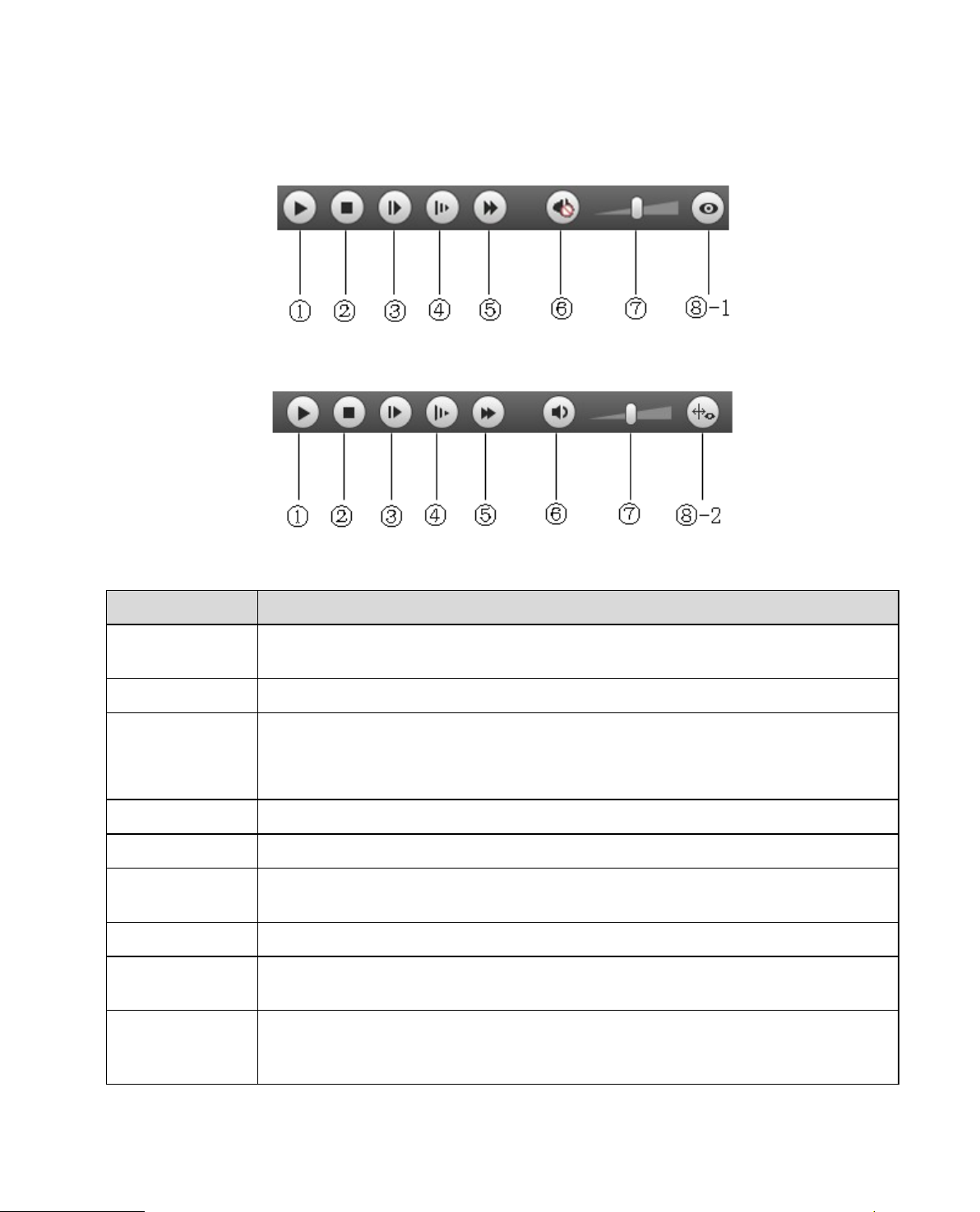
The function of play is show n as in Figure 4-2 and Figure 4-3.
Figure 4-2
Figure 4-3
Parameter Function
① Play
② Stop Click this button to stop playing.
③
frame
④ Slow Click on this button to play slowly.
⑤ Quick Click on this button to play quickly.
⑥ Silent
⑦ Volume Click on left mouse to adjust volume.
⑧ -1 Fisheye
⑧ -2 Rule Info
button, switch to normal play status.
Click on this button to go to next frame.
Note:
You shall pause record when y ou use this function.
When this button displays, it means audio is silent. Click on this button to switch
back to normal.
different installation mod e during the process of play back.
Clic
enabled, it is off by default.
Page 27
22
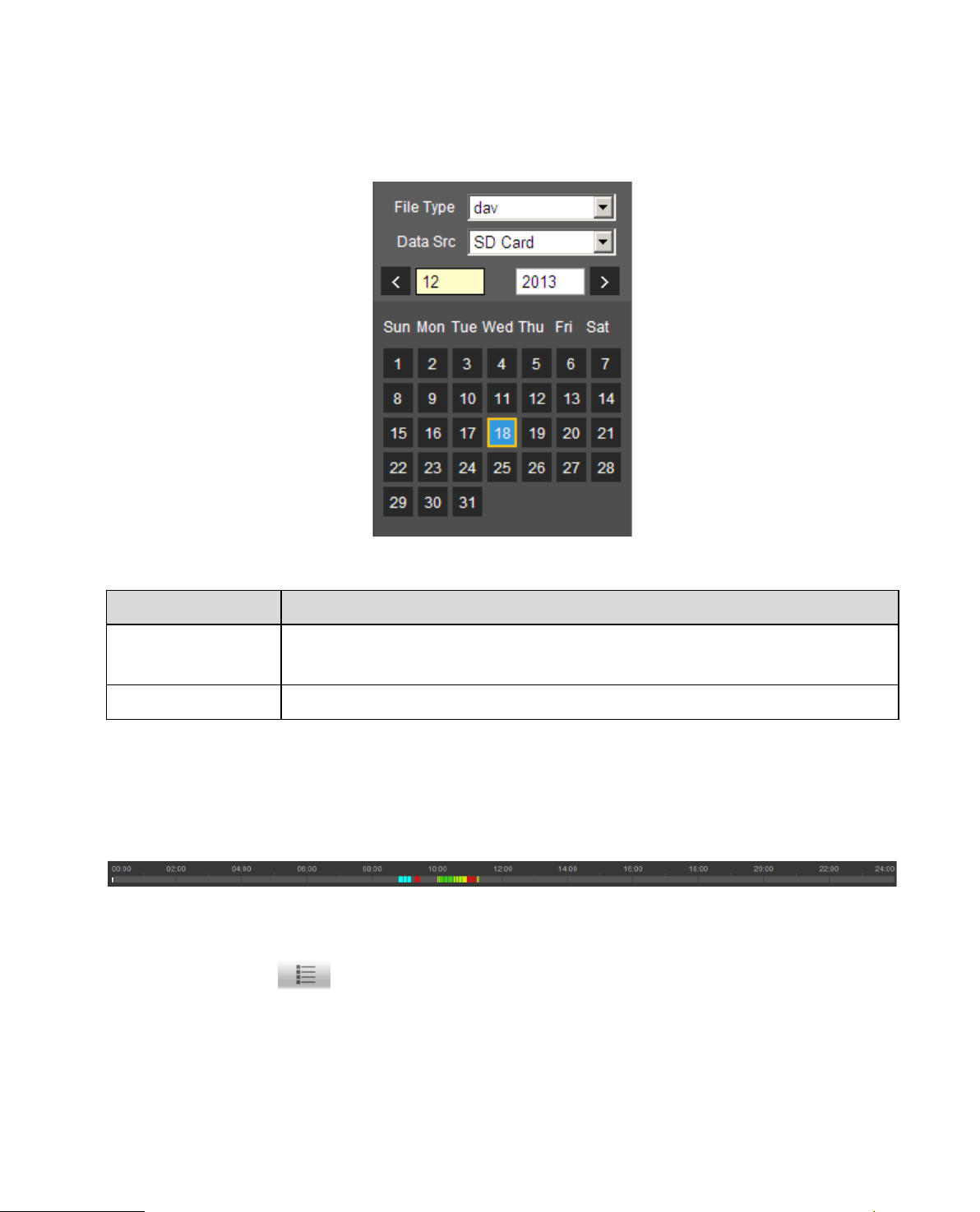
4.1.2 Playback File
In calendar, blue date represent s data currently has video record or snapshot. See Figure 4-4.
Figure 4-4
Parameter Function
File Type
Data Source Default is SD c a r d .
Step 1. Click on data in blue, time axis displays record file progress bar in color. While, green represents
normal record, yellow repr esent s motion detect record, r ed r epr esent s alarm record, and blue
represents manual recor d.
Step 2. Click on certain time on progress bar, playback starts from this time. See Figure 4-5.
Select “dav”, as video playback.
Select “jpg” as picture playback.
Figure 4-5
Step 3. Clic k on file list
Step 4. Double click on file in list, playback this file and display file size, start time and end t ime.
See Figure 4-6.
, select date file will be displayed in list.
Page 28
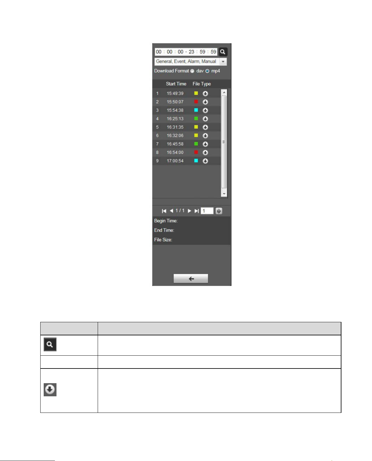
23
Figure 4-6
Parameter Function
Search
Record Format There are two formats: dav, mp4.
Download
It means records within searched start time and end time on t he dat e.
Click the download button and download fil e t o path in Ch. 5.1.2.5.
System does not support download and play back at the same time.
Page 29
24
Parameter Function
Back
Click on back button to go to c alen dar int erface.
4.1.3 Playback Cut
Note:
Playback cut function will aut omatically pause playing record as playback cut and playback cannot be at
the same time.
Step 1. Click on start time to cut on time axis. This time mu st be within progress bar range.
Step 2. Move mouse t o c ut ic on
finish cutting.
Step 3. Click on playback cut end time on time axis. This tim e mu st be within progress bar range.
Step 4. Move mouse t o c ut ic on
finish cutting.
Step 5. Click on Save but ton to save file cut to path in Ch 5. 1.2.5. See Figure 4-7.
. You will be ask to select start t ime. Clic k on c ur i con as
you will be asked to select end t i me. Click on cut icon as
Figure 4-7
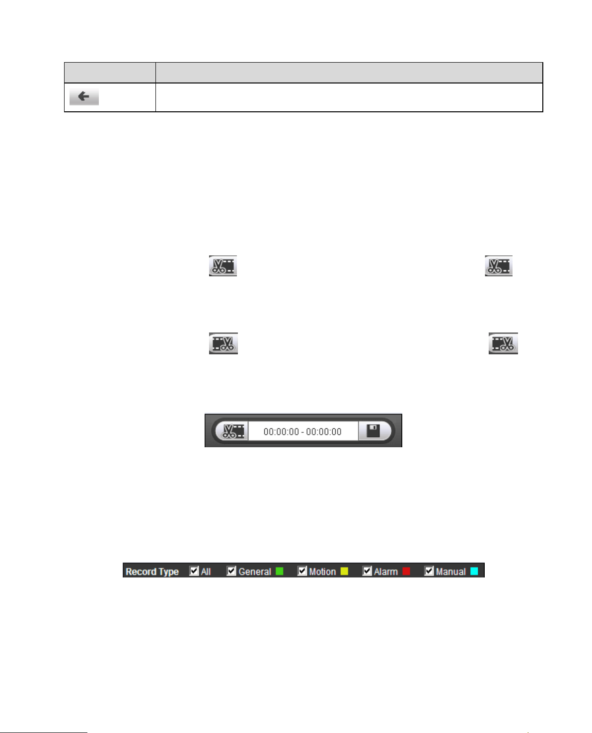
4.1.4 Record Type
After checking record file type, only selected file w i ll be displayed in progress bar and file list. Users can
also select the record type to be displayed via the dropdown box which is above the file list. See Figure
4-8.
Figure 4-8
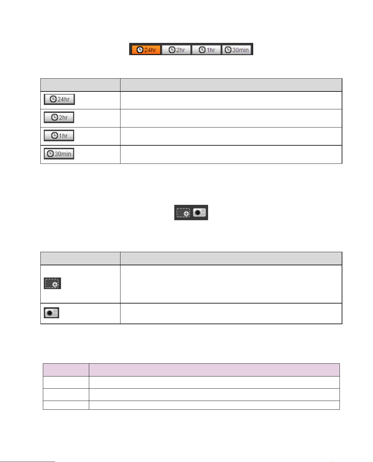
4.1.5 Progress Bar
Page 30
25
if is in original size, user can
ick on this button, you can snapshot video under playback status.
3
Snapshot type bar
Parameter Function
Figure 4-9
24 hours
2 hours
1 hour
30 min
Click on it, m eans video in past 24 hours.
Click on it, means video in past 2 hours.
Click on it, means video in past 1 hour.
Click on it, means video in past 30 min.
4.1.6 Assistant Function
Video playback assistant f unction is shown in Figure 4-10.
Figure 4-10
Parameter Function
Click on it, video in playback status
zoom in any area, If it is not in its original size, right c lick mous e to
Digital Zoom
restore its original size.
Click on this button, you can scr oll to zoom in.
Snapshot
Cl
Snapshot will be saved to path in Ch. 5.1.2.5.
4.2 Picture Playback
Web client picture playba ck interface has the following thr ee functions:
Parameter Function
1 Play function bar
2 Playback file bar
See Figure 4-11.
Page 31

26
Figure 4-11
4.2.1 Play
Figure 4-12
Default ico n is and it means pause or not p layed picture. Click on play butt on t o s w itc h t o
normal play status. Icon b ecome
Click on it to pause.
4.2.2 Playback File
Page 32

27
Figure 4-13
Step 1. Clic k on file list , select snapshot file of th e dat e.
Step 2. Double click on file in list, to play this snapsh ot .
Parameter Function
Search
It means all snapshot files within the start time and end time o f selected date.
Page 33

28
Click the download button to open snapshot file or directly download to local
Parameter Function
Download
Back
according to the browser types.
Click on back button to return t o calendar interface and re-select time.
Figure 4-14
4.2.3 Snapshot Type
Page 34

29
After checking snapshot file type, in file list only display file of selected type. Users can also select the
snapshot type to be displayed via the dropdown box above the f ile list. See Figure 4-.
Figure 4-15
Page 35

30
5 Setup
Web client setup support c amera, network, time, stor age, system and system info v iew.
5.1 Camera
The camera setting includ es c onditions, profile management, zoom and focus.
5.1.1 Conditions
Note:
The camera parameter m ay be different according to differ ent models, please refer to the act ual product
for more details.
5.1.1.1 Picture
Note:
The device which supports true WDR fails to support long exposure when true WDR is enab led.
Step 1
Select “Setup > Camera > Cond iti ons > Picture” and the system will di splay the “Picture” image whic h is
shown in Figure 5-1.
Figure 5-1
Step 2
Set picture parameters; please refer to the following s heet for more details about para meter s et t i ng.
Parameter
Style
Note
It is to set the picture style, w hich inc lu des s t andard, soft and vivid.
Page 36

31
It is to adjust the picture contrast. The bigger the value is, the bigger the
bright contrast becomes, and on the contrary it is smaller. The dark area
bright area becomes overexposed easily when
the value is set too big. The picture becomes blurry when the value is set
It is to adjust the color darkness and lightness. The color becomes darker
rary it becomes lighter. The value
It is to adjust the sharpness level of the picture edge. The bigger the
sharpness value is, the more obvious the image edge becomes, the image
It is to change image brightness and improve the dynamic display range of
the image via nonlinear adjustment mode. The bigger the value is, the
Flip mode 1: The monitoring picture is displayed with clockwise
Flip mode 2: The monitoring picture is displayed with anticlockwise
resolution as 1080P or lower when applying flip mode
flicker function via comparison algorithm of
image difference, which can effectively solve the problem of image jittering
Parameter
Note
It is to adjust the image overall brightness via linear adjustment mode.
Brightness
The larger the number is, the brighter the picture is, and on the contrary it
is opposite. The picture get blur ry easily when the value is set too b ig.
Contrast
becomes darker and the
too small.
Saturation
when the value is bigger; on the cont
causes no influence to the overall brightness of the image.
Sharpness
is likely to generate noise more easily when the value is set too big.
Gamma
brighter the picture becom es, and on the contrary it is opposite.
Mirror After mirror is enabled, the monitoring image will be displayed invertedly.
It is to change the display direction of the monitoring image.
It includes following option s :
Normal: The monitoring picture is normally displayed.
rotation 90°
Flip
rotation 90°
180°: The monitor ing p ict ure is displayed upside down.
Note:
Please set the video
for some devices.
It can realize electronic anti-
EIS
during application and it can make the image cleare r.
Step 3
Click “Save” and complete the image parameter con f ig of the camera.
Page 37

32
5.1.1.2 Exposure Step 1 Select “Setup > Camera > Cond it i ons > Exposure”. The system will display the “Exposure” inter f ace which is shown in Figure 5-2.
Figure 5-2
Step 2
It is to set the exposure parameter , please refer to the following she et for more details.
Parameter Note
Outdoor: You can switch to exposure mode w hen it is in
50Hz: When the current is 50Hz, system can auto adjust the
Anti-flicker
60Hz: When the current is 60Hz, system can auto adjust the
outdoor mode, it can reali ze the result in the corresponding
exposure mode.
exposure according to the environment brightness in case
there is any stripe.
exposure according to the environment brightness in cas e
there is any stripe.
Page 38

33
flicker” is “Outdor”, the “exposure mode” can be
Different devices have different exposure modes; please
Auto: It can auto adjust the image brightness according to
Gain priority: The device can auto adjust according to the
range according to the different scene brightness. The device
will auto adjust shutter value if the image brightness fails to
or lower limit, which is to make the image reach the best
Shutter priority: The device can auto adjust according to the
shutter range which is set by priority during normal exposure
range according to the different scene brightness. The device
reach the effect and the shutter value has reached to upper
limit or lower limit, which is to make the image reach the best
Iris priority: Iris value is fixed, the device can auto adjust the
the shutter value has reached the upper limit or lower limit,
Manual: It is to manually set gain value and shutter value,
It can set the parameter when the camera installs auto iris.
The lens iris can auto adjust the size according to the
environment after auto iris is enabled, then the image
reaches the max when disabling auto iris, the
lens iris will not change according to the environment
can realize noise reduction of the image by using the interframe
Parameter Note
It is the camera exposure mode.
Note:
W hen “Anti-
It includes the following opt ions:
Mode
set as “gain priority” or “ shut t er pr ior ity” mode.
refer to the actual interfac e.
the environment.
gain range which is set by priority during normal exposure
reach the effect and the gain value has reached to upper limit
brightness.
will auto adjust shutter value if the image brightness fails to
brightness.
Auto Iris
3D NR
shutter value if the image brightness fails to reach effect and
the device can auto adjust the gain value to make the image
reach the best brightness.
adjust the the displayed brightness of the image.
brightness will change accordingly.
The iris value
brightness.
It is to process the image with multiframe (at least two frames), it
information between the p r evious and latter frame.
Grade
It can set the parameter when “3D NR” is enabled.
The bigger the grade is, the bett er N R ef fe ct it can realize.
Page 39

34
Step 3
Click “Save” to complete the par ameter config of camera exposure.
5.1.1.3 Backlight Backlight mode can be divided into BLC, WDR and HLS. BLC: it can avoid cucolori s phenomenon of the darker area in the backlight environment. WDR: It can suppress the overbright area and compensat e darker area by enabling WDR, w hich can make the overall image cl ear. HLC: It is to weaken the hi gh light , which can be applied in the areas such as toll gate, entrance and exit of the parking lot and etc. As for extreme light, it can snapshot the human face in the dark environment and it can realize better effect for the details of the p late number.
Step 1
Select “Setup > Camera > Cond it i on > Backlight”, the system will disp lay the interface of “Backlight”
which is shown in Figure 5-3.
Figure 5-3
Step 2
Set the backlight parameter.
When the “Mode” is set as “Scene Self-adapt at ion”, the system will auto adjust t he image
brightness according t o t he environmental brightnes s, w hich is to make the object display clearly in
the scene.
When the “Mode” is set as “BLC”, it can select de fault mode or customized mode.
When selecting “Default” mode, t he system can realize auto expos ur e according to the
environment, which is to ma ke t he i m age in the darkest area clear to be se en.
Page 40

35
When selecting “Customized” m ode, t he s ystem can realize exposure upon the selected area
after it set customized are a, w hich is to make the image of the selecte d ar ea reach
appropriate brightness.
When the “Mode” is set as “WDR”, it will lower the brightness of the area with hig h br ig htness and
enhance the brightness of the area with low brightnes s, w hich i s to make the objects in both high
brightness and low brightn ess ar ea display clearly.
Note:
There may be video loss of a few seconds when the camera is sw itched from non WDR mode to WDR
mode.
When the “Mode” is set as “HLC”, the system wil l constrain the brightness of the area w it h high
brightness and decrease t he s iz e of the halo area, which is to lower the brightness of the whole
image.
Step 3
Click “Save” to complete the config of the backlight mode.
5.1.1.4 WB WB is used to restore the white object in the scene by the camera, after WB mode is set, it can make the white object look white in different environments . Step 1 Select “Setup > Camera > Cond it i ons > WB”, the system will display t he int er f ace of “WB”, which is shown in Figure 5-4.
Figure 5-4
Step 2
Set WB mode.
Page 41

36
When the “Mode” is set as “Auto”, the system can a uto compensate white balance upon different
color temperatures, wh ich is to make the image color normal.
When the “Mode” is set as “Natural”, the system can auto compensate white balance to the scene
without artificial light, which is to make the image color nor mal.
When the “Mode” is set as “Street Lamp”, the system can auto compensate white balance to the
outdoor scene at night, which is t o m ake the image color normal.
When the “Mode” is set as “Outdoor”, the sy stem can auto compensate white bal anc e to the most
outdoor scenes with natur al l ight and artificial light, which is to m ake the image color normal.
When the “Mode” is set as “Manual”, it can manually set the value of red gain and blue g ain; t he
system can compensate t he different color temperat ur es in t he environment accord ing to t he
settings.
When the “Mode” is set as “Regional Custom”, it is to set customized area, the sy stem can
compensate white balan ce to different color temper at ur e of the images in the area, which is to
make the image color norma l.
Step 3
Click “Save” to complete the config of WB mode.
5.1.1.5 Day & Night It is to set the switch between co lor mode and blac k & white mode. Step 1 Select “Setup > Camera > Conditions > Day & Night” and the system will display the int er fac e of “Day & Night”, which is shown in Fig ur e 5-5.
Figure 5-5
Page 42

37
It is to set the camera image displ ayed as color or black & white mode.
The setting of “Day/Night Mode” is not affected by the setting of “Profile
Auto: The camera can auto select color image or black & white image
Black & white: The camera image is displayed as b l ack & white image.
The parameter can be set when the “Day/Night Mode” is “Auto” .
It is to set the sensitivity of the switch between image color display and
black & white display.
The parameter can be set when the “Day/Night Mode” is “Auto” .
color display and black & white display.
Step 2
Set day & night parameter; please refer to the following sheet for more details.
Parameter Note
Note:
Management”.
Mode
Sensitivity
It includes the following opt ions:
Color: The camera image is displayed as color im age.
to be displayed according t o t he environmental brightness.
Delay
Step 3
Click “Save” to complete the config of day/night mode.
It is to set the switch delay between image color display and white & black
display. The smaller the delay is, t he faster of the switch becomes between
5.1.1.6 Defog The image quality will becom e weak when the device is in the environment with fog or haze, you can enable defog function to a djust t he image definition. Step 1 Select “Setup > Camera > Cond it i ons > Defog” and the system will dis play the interface of “Defog” which is shown in Figure 5-6.
Page 43

38
Figure 5-6
Step 2
It is to set defog mode according to the actual scene.
When the “Mode” is set as “Manual”, it is to manua lly set intensity and air light mo de, t he s ystem
will adjust the image defin i t ion according to the intensity and air l ight mode which have been set
previously. As for air light mo de, you can set manual or auto.
When the “Mode” is set as “Auto”, the system wil l au t o adjust the image definition accor di ng t o t he
actual scene.
When the “Mode” is set as “Off”, then the defog fu nction is disabled.
Step 3
Click “Save” to complete the config of defog mode.
5.1.1.7 IR Light You can directly set the mode o f IR l ight if the device is equipped with I R light . Step 1 Select “Setup > Camera > Cond it i ons > IR Light” and the system will display the interface of “IR Light ” which is shown in Figure 5-7.
Page 44

39
Figure 5-7
Step 2
It is to set IR light mode according to the actual scene.
When the “Mode” is set as “Manual”, it can manually set the brightness of IR light ; the system will
realize light compensat ion to the image according to t he I R light int ensity.
When the “Mode” is set as “Smart IR”, the sy st em can adjust the light brightness accor ding to the
actual scene.
When the “Mode” is set as “Zoomprio”, the sy st em c an auto adjust the IR light accordin g t o the
brightness change of the act ual s cene.
The system will enable near light by pr ior ity when the actual scene beco mes dark, the system
will enable the far light when t he near l ight fails to meet the requirement of scene brightness
even if it is adjusted to the brightest .
The system will adjust far light brightnes s by priority to off and then adj ust t he br ight ness of
near light when the actual scene becomes bright. The syst em will always disable far light
when the focal length of the lens is ad just ed to a certain wide angle, w hich i s t o avoid near
overexposure. Meanwh i le, it can manually set light compensation to slightly adjust the
brightness of IR light.
When the “mode” is set as “Off”, it will not enable th e IR light.
Step 3
Click “Save” and complete the config of IR light.
5.1.1.8 Profile Management Step 1 Select “Setup > Camera > Cond it i ons > Pr ofile Management” and the system will display the interfa c e of “Profile Management”.
Page 45

40
Step 2
Set profile management.
When the “Pro file M anagement” is set as “Norma l”, t he s ystem will monitor accordin g t o the normal
config.
Figure 5-8
When the “Pro file Management” is set as “Full Time”, you can select “Always E nable” in “Day” or
“Night’, the system will monitor according to the config of “always enable”.
Figure 5-9
When the “Pro file Management” is set as “Schedule”, you can set some period as day and another
period as night, for example, i f it set s 0:00~12:00 as day, 12:00~24:00 as night , t hen the system will
monitor by adopting corresponding config in differen t periods.
Figure 5-10
Step 3
Click “Save” to complete the settings of profile manageme nt .
Note:
Click “Default” to restore t he device to default config; clic k “ Re fres h” to check the latest config file o f the
device.
Page 46

41
5.1.1.9 Zoom and Focus Note:
Only motorized vari-focal devices support focus and zoom funct i on.
Step 1
Select “Setup > Camera > Cond it i ons > Zoom and Focus” and the sy stem will display the interface of
“Zoom and Focus” which is shown in Figure 5-11.
Figure 5-11
Step 2
Adjust the focal length of the lens.
After it is zoomed, set “Speed” and press “+”, “-“or drag the sliding block directly to adjust.
Step 3
Adjust the lens definition.
After it is focused, set “Speed” and press “+”, “-“or drag the slid ing block directly to adjust.
Note:
Speed is used to set the length by pressing “+” and “-“.
After adjusting the focal length of the lens or cl ick “Auto Focus”, the device will auto adjust the
image definition, it is not allow ed to implement other lens oper ation during auto focus.
After several times of zoom and focus, the image fa ils to be adjusted clear, click “Restore All’ to
reset the lens to zero and remove the accumulative error of the lens.
Click “Refresh” and the device will automatically synchronize t he har dw ar e t o t he location of sliding
block of lens zoom and focus.
5.1.2 Video
Page 47

42
5.1.2.1 Video Step 1 Select “Setup > Camera > Video > Video” and the system will display the interface of “Video” which is shown in Figure 5-12 or Fi gur e 5-13.
Step 2
Figure 5-12 (Non fisheye)
Figure 5-13 (Fisheye)
Page 48

43
It will display the paramet er when the device is fisheye.
display the dewarped image on the third-party platform.
It will display the paramet er when the device is fisheye.
Set video bit stream, please refer to the following sheet for more details about the para meter s.
Parameter Function
Installation Mode
Record Mode
There are three installation modes for fisheye which ar e
ceiling, wall mount and gr ound installation, please
select installation mode a ccor ding to the actual
installation scene of the fisheye.
The system will begin to swit ch after switching
installation mode, it will pr om pt suc cessfully saved after
it is switched successfully.
Note:
The device end will output t he dewarped video stream
after configuring installat ion and record mode, when the
device is accessed to third-p a rty platfor m, it will direc tly
The system will begin to swit ch after r ecord mode is
switched, it will prompt sa ved successfully after it is
switched successfully.
The record mode will change ac c or ding to the different
installation modes.
1O: the original picture which is not dewarped.
1P: 360°rectangular panorama.
2P: The mode can be set when the “Installation
Mode” is set as “Ceiling” or “Ground”. It is the 2
related 180°rectangular image, t he t wo
subwindows can both for m 36 0°panorama anytime.
1O+3R: original image + 3 independent su b
images, both the sub image and s ub boxes in the
original image can support zoom and movement.
1R: Original image + independent sub image, the
sub boxes of the original i ma ge support zoom and
movement.
4R: original image + 4 independent sub images,
both the sub image and sub boxes in t he original
image support zoom and mov ement.
2R: Original image + 2 independent sub images,
the sub boxes of the original im age can support
zoom and movement, the sub i m age supports up
and down movement, whi ch can change the
vertical angle of view.
Note:
The device end will output dew ar ped video stream after
configuring installation and record mode, when the
device is accessed to the third-party platform, it will
directly display the dewarped image on the third-party
platform.
Page 49

44
Select “Enable” to enable sub s t r eam.
stream 2 at the same time.
It can enhance image compression performance a nd
please refer to the actual int er face for more details.
ACF means using differen t fps to r ec or d.
code stream setting.
There are five options: H.264 (ma in profile standard,
recommend bit to get the bet t er video output effect.
There are two options: VBR and CBR.
Under MJPEG mode, only CBR is available.
Parameter Function
Sub Stream Enable
Smart Codec
Code-Stream Type
Encode mode
The device supports enab lin g sub s t r eam 1 and sub
reduce storage space by enab li ng i nt elligent encoding.
Note:
After intelligent encodin g i s enabled, the device will not
support third stream, ROI or intelligent event detection,
There are two options: VBR and CBR.
Please note you can set video qu al ity in VBR mode.
Note:
WEB interfaces don’t support motion detect and ala r m
H.264H (high profile stand ar d) , H.264B (Baseline
Profile), H.265 (main profile standard) and MJPEG
encode.
The H.264, H.264H both are H264 bit stream.
H.264 is the Main Profile encode and you need to
enable the sub stream funct ion i n your camera and
set the resolution as CIF. Then you can monitor via
the Blackberry cell phone.
The H.265 is the main profile encode mode.
MJPEG: In this encode mode, the video needs to
large bit stream to guarantee the video definition.
You can use the max bit stream v alu e in t he
Resolution
Video Clip
Frame Rate (FPS)
Bit Rate Type
Recommended Bit
There are multiple resoluti ons. You can select from the
dropdown list.
For each resolution, the recommended bit stream v alue
is different.
Note: When video is unde r rotating status, you cannot
set resolution higher than 1080P (excluding 1080P).
The function is only suppor t ed by sub stream 2, please
refer to “Video Clip” for mor e details below the sheet.
PAL: 1~25f/s,1-50f/s NTSC: 1~30f/s or 1~60f/s.
The frame rate may vary due to different resolutions.
Please note, you can set video quality in VBR mode.
Recommended bit rate v al ue ac cording to the resolution
and frame rate you have set.
Page 50

45
In CBR, the bit rate here is the max value. In
information.
Parameter Function
Bit Rate
dynamic video, system ne eds t o low frame rate or
video quality to guarantee the value.
The value is null in VBR mode.
Please refer to recommend bit rate for the detailed
SVC
I Frame
Watermark Settings
Watermark Character
Frame rate can be encoded by layer. It is a flexible
encoding method. By defa ult , it is 1 as 1 l ayer. You also
can set 2/3/4 layers.
Here you can set the P frame amount between two I
frames. The value ranges from 1 to 150. Default value
is 50.
Recommended value is fr am e r at e * 2.
Select “Watermark Setting” and enable watermark
function. After the water m ar k fun ct ion is enabled, you
can check if the video is tampere d via verifying
watermark character.
It is the character of watermar k ver ification, it is
DigitalCCTV by default.
Video Clip
1. Select “Sub Stream 2” in the drop-down box, click “Enable”.
2. Enable “Video Clip”, clic k
The system will display t he inter f ace of “Area”, which is shown in F igure 5-14.
.
Page 51

46
Figure 5-14
3. Select the needed resolution and clip the needed image on the interface, which is shown in Figure
5-15.
4. Click “Save”. You can che ck the clipped video in the prev iew inter f ace ( t he s ub stream 2 preview
interface only displays t he c lipped area), which is shown in Fig ur e 5-15.
Page 52

47
Figure 5-15
Step 3
Click “Save” to complete v ideo stream setup.
5.1.2.2 Snapshot The snapshot interface is shown as in Figure 5-16.
Figure 5-16
Please refer to the following sheet for detailed information.
Page 53

48
There are two modes: general (schedule) and Event (activation).
It is to set the image quality. Ther e ar e six l evels.
It is to set snapshot frequency . O ptional1~7s/picture, customized.
Parameter Function
Snapshot type
Image size It is the same as the resolut ion of main stream.
Quality
Interval
5.1.2.3 Video Overlay The video overlay interfac e is shown as in Figure 5-17.
Figure 5-17
Page 54

49
Figure 5-18
Figure 5-19
Page 55

50
Figure 5-20
Figure 5-21
Page 56

51
Here you can privacy mask the specified video in the
System max supports 4 privacy mask zones.
You can enable this function so that system over l ays time
You can use the mouse to drag the time tile position.
You can enable this function so that system over l ays
You can use the mouse to drag the channel tile position.
You can enable this function to overlay text in video
position. Alignment inclu de align left and align right.
You can enable this function to display overlay picture.
You cannot enable text and pict ur e overlay at the same time.
Check “Enable” to display the counting statistics data in
type and left align and right alig n f or O SD info.
Figure 5-22
Please refer to the following sheet for detailed information.
Parameter Function
Privacy Masking
Time Title
Channel Title
Text Overlay
Picture Overlay
Counting
monitor video.
information in video windo w .
channel information in video window.
window.
You can use the mouse to drag location box to adjus t its
Click on disable to turn it off.
Click on Upload Picture to overlay local picture into
monitoring window. You c an dr ag t he yellow box to move
it.
Note:
the video monitoring window; check “Disable” not to
display.
There are enter number a nd le ave number for statistics
Page 57

52
Set privacy mask, channel title, time title, locat ion, overlay
effect.
Click it to restore default config.
Click it to complete video settings.
Refresh
Default
Save
5.1.2.4 ROI Note: Some series don’t suppor t RO I set up function.
and save the change. You can cl ick on Refresh to see
Figure 5-23
Page 58

53
Parameters Note
Figure 5-24
Enable
Image
Quality
5.1.2.5 Path The storage path interface is show n as in Figure 5-25. Here you can set snap image saved path and the recor d st or age path.
The default monitor image path is C:\Users\admin\WebDownload\LiveSnapshot.
The default monitor record path is C:\Users\admin\WebDownload\LiveRecord.
The default playback snapshot path is C:\Users\admin\WebDownload\PlaybackSnapshot.
The default playback download path is C:\Users\admin\WebDownload\PlaybackRecord.
The default playback cut pat h is: C:\Users\admin\WebDownload\VideoClips.
Note:
Admin is locally logged in PC a ccount.
Please click the Save button t o s ave current setup.
Check “Enable”, then it wi l l dis pl ay the ROI in the video monitorin g w indow;
Check “Disable”, then it won’t di splay.
Set the image quality of ROI, ranging from 1~6, default is 6.
Note:
For fisheye device, it ranges from 1~6 (best), default is 6 (best)
Able to set area block, max 4 areas .
Figure 5-25
5.1.3 Audio
Please note some series devices do not sup port a udi o function.
5.1.3.1 Audio The audio interface is sho w n as below. See Figure 5-26.
Page 59

54
Figure 5-26
Please refer to the following sheet for detailed information.
Parameter Function
Enable You can enable audio onl y when video is enabled.
After selecting the “Enabl e” of main stream or sub stream, the
network transmission stream is the audio/video composit e
stream, otherwise it only i ncludes video image.
Encode mode
Sampling
Frequency
The encode mode of the main str eam and extra stream inclu de
G.711A, G.711Mu, G.726 and ACC. The default mode is
G.711A.
The setup here is for audio encode mode and the bidirect ion al
talk encode both.
The sampling frequency of audio. It includes the following
options:
8K
16K
32K
48K
64K
Page 60

55
Speaker Volume
AudioIn Type
Noise Filter Enable t he fu nc t io n and it can filter relevant noise.
Microphone
Volume
5.1.3.2 Alarm audio
Two modes to select: LineI n, M ic. Device needs to connect
external audio input source under LineIn mode, and it does n’t
need to connect external audio input source under Mic mod e.
Adjust microphone volume from 0~100.
Note:
Supported by some devices.
Adjust speaker volume from 0~100.
Note:
Supported by some devices.
Figure 5-27
Figure 5-28
and can select an audio file for the audio alarm linkage.
Audio management currently supports PCM format to record and PCM, wav two for ms to upload,
The way to download the web alarm playback audio file into local is as follows:
Page 61

56
Step 1 Use the left mouse button to click the hollow circle in the “choice” column on the le f t,
and shows
Step 2 Use the r ight mouse button to click
,which means effec t iv e c hoice of alarm audio.
,select “save t arget as” to download.
5.2 Network
5.2.1 TCP/IP
The TCP/IP interface is shown as in Figure 5-29. It supports IPv4 and IPv6. IPv4 supports stat ic IP and
DHCP. IPv6 supports static IP only. When users manually modify IP address, WEB will automatica l ly
jump to the new IP address.
Figure 5-29
Please refer to the following sheet for detailed information.
Parameter Function
Host Name
Ethernet Card Please select the Ethernet por t . Defa ult i s w ired.
Mode
Mac Address It is to display hose Mac address.
It is to set current host device name. It max supports 15
characters.
Please note you can modify the default Ethernet card if ther e is
more than one card.
There are two modes: static mode and the DHCP mode. Select
DHCP mode, it auto searc hes I P, and you cannot set IP/subnet
mask/gateway. Select st atic mode, you must manua lly set
IP/subnet mask/gateway .
Page 62

57
IP Version It is to select IP version. IPV4 or IPV6.
You can access the IP addr ess of these two versions.
IP Address
Preferred DNS DNS IP address.
Alternate DNS Alternate DNS IP address.
Enable
ARP/Ping set
device IP
address service.
Please use the keyboard to input the corresponding nu mber t o
modify the IP address and t hen set t he c orr es ponding subnet
mask and the default gate w ay.
You can use ARP/Ping com m and t o modify or set the device IP
address if you know the device MAC address.
Before the operation, please make sure the network cam er a
and the PC in the same LAN. This function is on by default.
You can refer to the steps listed below.
Step 1: Get an IP address. Set the network ca mera and the PC
in the same LAN.
Step 2: Get the physical address fro m the l abel of the network
camera.
Step 3: Go to the Run interface and t hen input the following
commands.
arp –s <IP Address> <MAC>
ping –l 480 –t <IP Address>
Such as:arp -s 192.168.0.125 11-40-8c-18-10-11
ping -l 480 -t 192.168.0.125
Step 4: Reboot the device.
Step 5: You can see the setup is OK if you ca n see there are
output information such a s “ Rep ly from 192.168.0.125 …” from
the command output lines. Now you can close the command
line.
Step 6: Open the browse and then input http://<IP address>.
Click the Enter button, you can access now.
5.2.1.1 P2P Click “Enable” to connect t he device to network, and then you can connect to the device via mobile
client of P2P after “Online” is displayed o n t he int erface (connection mode: add device serial number or
scan QR code). See Figure 5-30.
Page 63

58
Figure 5-30
5.2.2 Connection
5.2.2.1 Connection The connection interface is shown as in Figure 5-31.
Figure 5-31
Please refer to the following sheet for detailed information.
Parameter Function
Max
connection
TCP port
It is the max Web connection for the same device. The value ran ges from 1
to 20. Default connection am ount is 10.
Port range is 1025~65534. The default value is 37777. You can i nput the
actual port number if nece ssar y.
Page 64

59
UDP port
HTTP port
RTSP port
HTTPs
Port
Port range is 1025~65534. The default value is 37778. Y ou can input the
actual port number if nece ssar y.
Port range is 1025~65524. The default value is 80. You can input the
actual port number if nece ssar y.
The default value is 554. Please leave blank if use default. User uses
QuickTime or VLC can pla y the following formats. Blac kBer r y can play
too.
Real-time monitoring URL format, ple ase r equire real-time RTSP
media server, require channel no., bit stream type in URL. You may
need username and passw or d.
User uses BlackBerry need to set encode mode to H. 264B, resolution
to CIF and turn off audio.
URL format is:
rtsp://username:password@ip:port/cam/realmonitor?channel=1&subtype=0
Username/password/IP and port.
The IP is device IP and the port def ault value is 554. You can leave it in
blank if it is the default value.
Follow standard RTP protocol and when encode mode is MJ PEG , t he max
resolution only supports 2040*2040.
HTTPs communication port, range is 1025~65534, def ault is 443.
Note:
0~1024, 37780~37880, 1900, 3800, 500 0, 5050, 9999, 37776, 39999, 42323 are all special ports.
User cannot modify them.
Avoid using default port value of other ports.
5.2.2.2 ONVIF(Open Network Video I nt er face Forum),this stan dard describes network video mode,
interface, data type and data int erac tion mode. ONVIF Standard’s aim is to achieve a network video
frame agreement and makes t he net w ork video products (inclu di ng video front-end, video equipment,
etc.) from different manuf act ur er s completely compatible.
ONVIF function is on by defa ult.
ONVIF
Page 65

60
Figure 5-32
5.2.3 PPPoE
The PPPoE interface is shown as in Figure 5-33.
Enter the PPPoE username and password which ar e pr ovided by ISP (Internet Serv ice Provider), and
click “Enable”. The networ k c amera will automatically establish network connection in the mode of
PPPoE after it is enabled, after it is successful, the IP of the “ I P Address” will be automatically modified
into the dynamic IP addre ss of t he acquired WAN.
Note:
After PPPoE dial-up is successful, it needs to log in the device via the IP which is set before dial-up; in
the PPPoE setup interfac e, it will display the registered I P address, and then it can visit the I P addr ess
via client.
Please disable UPnP whe n cli cking PPPoE enable, which is t o avoid causing influence to PPPoE dialup.
Page 66

61
Figure 5-33
5.2.4 DDNS
The DDNS interface is sh ow n as in Figure 5-34.
The DDNS is to set to connect the various servers so that you can ac cess the system via the server.
Please go to the correspo ndi ng ser vice website to apply a doma in n ame and then access the syste m
via the domain. It works even your IP address has changed. When the device connects to WLAN, you
should disable UPnP.
Figure 5-34
Please refer to the following sheet for detailed information.
Parameter Function
Server Type
Server Address DDNS server IP address
Mode Default is auto, it can select manual
Domain Name
Click it to select DDNS pr ot ocol type, which includes: ICDDNS,
NO-IP DDNS, Dyndns DDNS, the default is ICDDNS.
ICDDNS
Server address: www. icddns.com
NO-IP DDNS
Server address: dynupdate.no-ip.com
Dyndns DDNS
Server address: members .dyndns.org
Both auto and manual are “M AC addresss.icddns.com” by
default, it is able to set prefix m anually.
Page 67

62
Parameter Function
Username The user name you input to log in the ser ver, optional.
The ICDDNS interface is shown as in Figure 5-35.
Figure 5-35
Parameter Function
Server Type You can select ICDDNS protocol
Server Address Under ICDDNS the default server address is “ www.icddns.com”
Mode Default is auto, manual is opt ional.
Domain Name
Test
Username The user name you input to log in the ser ver, optional.
The default is “MAC address. icd dns. com” for both auto and manua l, for manual
users can set prefix by the ms elv es .
It is to test if the domain name can be used or not. The param et er exists only when
selecting “manual” in “Mode”.
5.2.5 IP filter
The IP filter interface is show n as in Figure 5-36.
You can enable IP filter funct ion so that some specified IP/MAC user can access the network camera.
You can add IP address or I P segment.
If you do not check the box here, it m eans t here is on access limit.
Page 68

63
Here you can add IP address and MAC address. You must add t hese addresses before enabling the
trusted sites.
Please note: You must set MAC address in the same network segment.
Figure 5-36
5.2.6 SMTP (e-mail)
The SMTP interface is sh own as in Figure 5-37.
Figure 5-37
Please refer to the following sheet for detailed information.
Page 69

64
Input server address and then enable this function.
The user name of the sender email account.
The password of sender e ma il account.
Sender email address.
You can select SSL, TLS or none.
Input email subject here.
System can send out the email of the snapshot picture once
Input receiver email addre ss here. Max three addresses.
The send interval ranges fr om 0 to 3600 seconds. 0 means
load for the email server.
Please check the box here to ena b le this functio n.
The system will automatic ally sent out a email once to test the
the email setup information.
Parameter Function
SMTP Server
Port Default value is 25. You can m odify it if necessary.
Anonymity
User Name
Password
Sender
Authentication
(Encryption
mode)
Title (Subject)
Attachment
Mail receiver
Interval
For the server which support s t he anonymity email function, it
won’t display the informati on of the sender.
you check the box here.
there is no interval.
Please note system will n ot send out the email immediately
when the alarm occurs. When the alarm, motion detection or
the abnormity event act ivates the email, system sends out the
email according to the interval you specified here. This
function is very useful when t her e ar e t oo many emails
activated by the abnormity events, which may result in he avy
Health mail
enable
Email test
connection is OK or not .Befor e the email test, please save
5.2.7 UPnP
It allows you to establish the mapping relationship bet w een the LAN and the public network.
Here you can also add, modify or remove UPnP item. For UPnP on different routers, you must disable
UPnP function. See Figure 5-38.
In the Windows OS, From Start->Control Panel->Add or remove programs. Click the “Add/Remove
Windows Components” and then select the “Network Services” from the Windows Co m ponents Wizard.
Click the Details button and t hen check the “Internet Gateway Device Discovery and Contro l cl ient” and
“UPnP User Interface”. P l eas e click OK to begin installation.
Page 70

65
Enable UPnP from the Web. If your UPnP is enabled in the Window s OS, the network camera can aut o
detect it via the “My Networ k Pl aces ” .
Under manual mode, you can modify external port. Under auto mode, select idle por t for aut o por t
mapping without user modification.
Figure 5-38
5.2.8 SNMP
The SNMP interface is sh ow n as in Figure 5-39 and Figure 5-40.
The SNMP allows the com m uni cat ion between the network management work station so ftw ar e and the
proxy of the managed device. Please install the softw ar e such as M G MibBrowser 8.0c software or
establish the SNMP serv ic e bef or e you use this function. You nee d t o r eboot the device to activate the
new setup.
Page 71

66
Read-only access to all SNMP targets, default is public.
Note: Only number, letter, _, and – supported.
Read/write access to all SNMP targets, default is private.
Note: Only number, letter, _, and – supported.
The destination address of the Trap information fro m the
SNMP trap is a proxy messag e sent to admin as important
event notice or status cha nge.
Address where to send Trap m essage.
Port which send Trap message, default is 162, range
1~65535.
Figure 5-39
Please refer to the following sheet for detailed information.
Parameter Function
SNMP Version Check SNMP v1, device only process v1 info.
Check SNMP v2, device only process v2 info.
Check SNMP v3, can set username, passwor d and
encryption method. Server calibrate correspondi ng
username, password and encr yption method too access
device and v1/v2 are unavailable.
SNMP port
Community
Read community
Write community
Trap address
Trap
Trap Address
The listening port of the proxy program of the device. It is a
UDP port not a TCP port. The valu e r anges from 1 to 65535.
The default value is 161
It is a string, as command bet w een management and proxy, ,
defining a proxy, and a manager ’s authentication.
proxy program of the devic e.
Trap Port
Page 72

67
Default is public.
Name only can be number , letter and underline.
Default is private.
Name only can be number , letter and underline.
Figure 5-40
Check SNMP v3 version a nd SNMP port, read community , write community, Trap address , Trap port
are same with SNMP v1 and SNMP v2 versions. Only when SNMP version is SNMP v3, users ne ed to
configure parameter in chart.
Parameter Function
SNMP Version SNMP v3
Read-only
Username
Read/Write
Username
Authentication
Authentication
Password
Encryption
Encryption
Password
Note:
Note:
You may select MD5 or SHA, default is MD5.
Password not less than 8 charac t er s.
Default is CBC-DES.
Password not less than 8 charac t er s.
Page 73

68
5.2.9 Bonjour
The Bonjour interface is shown as below. See Figure 5-41.
Bonjour is based on the multic ast D NS service from the Apple. The Bo njour device can automatically
broadcast its service information and listen to the service information from other device.
You can use the browse of the Bo nj our ser vice in the same LAN to sear ch t he network camera device
and then access if you do not know the network camera infor mation such as IP address.
You can view the server name w hen t he network camera is detected by the Bonjour. Pleas e not e t he
safari browse support this function. Click the “Dis p lay All Bookmar ks: and open the Bonjour, system can
auto detect the network camer a of the Bonjour function in th e LAN.
Figure 5-41
5.2.10 Multicast
The multicast interface is shown as in Figure 5-42.
Multicast is a transmissio n mode of data packet. When there is multiple-host to receive the same data
packet, multiple-cast is the best option to reduce the broad width and the CPU load. The source host
can just send out one data to t r ansit. This function also depends on the relationship of the grou p
member and group of the outer .
Note:
Open preview, streaming media protocol, select multicast, and monit or via multicast format.
Here you can set multicast address and port. Y ou also need to go to Live interface to set the
protocol as Multicast.
Page 74

69
Figure 5-42
Please refer to the following sheet for detailed information.
Parameter Function
Enable
Multicast address
Port
Select to enable multicast function. Main stream and sub stream cannot be
used at the same time.
Main/sub stream multicast default ad dress is 224.1.2.4 and its range is
224.0.0.0~239.255.255.255.
Multicast port. Main stre am is 40000, sub stream1 is 40016, sub stream2 is
40032 and the range is 1025~65534.
5.2.11 4G
Note: This function is only for ser i es w ith 4G module.
4G is a mobile communic at ion system which makes wir eles s c ommunication integrates w ith I nt er net
and multimedia communicat ion.
5.2.11.1 Dialing Setting
Page 75

70
Parameter Function
Figure 4-53
Wireless Net Type
Enable Check to enable 4G module.
APN
Authentication Mode
Dial-up Number
User name It shall be acquired from t he operator.
Password It shall be acquired from t he operator.
Update Period
Time Range
Auto, WCDMA, FDD-LTE optional, you can select accor ding
to the operator.
It shall be acquired from t he operator according to the setup
of operator.
Auto, PAP and CHAP, the aut hent ication algorithm is
different according to different operators.
The number is different accor di ng t o different operator, it can
be acquired from operator.
It is the period beyond the dial-up period which has been
set, it is 30s by default, which means the device can auto
acquire 4G dial-up status, cut off dial-up to save flow.
It is the time period to set dial-up. It can activate the functio n
via message to enable/dis able dial-up function if it is
beyond the time period.
IP Address
It will displ a y the acquired IP after the dial-up is successful
via 4G.
Page 76

71
5.2.11.2 Mobile Setting
Figure 4-54
Please refer to the following sheet for detailed information.
Parameter Function
Message Send In the ev ent , after t he c or r esponding message activ at ion i s
enabled, it will send mess age t o t he phone of receiver when
event happens. It needs to enab le t he function of message
activation function in the e vent interface when using the
function.
Message
Activation
Phone Activation
It can send message ON/ O FF to t he SI M car d inside the device by
the mobile phone in the list, which is to enable /disable the dial-up
function and send REBO OT to restart the device.
You can use the mobile phone in t he calling list to call the SIM card
inside the device to enable dia l-up fun ctio n.
5.2.12 WIFI
Note:
Some series devices don’t support WIFI and WPS fu nct ion.
WPS function is supported by the devices with WPS button.
5.2.12.1 WIFI WIFI info can show the name, stat us, IP information of the Curr ent Hot Spot. Usually please “Refr es h” WIFI work information after reconnection to ensur e the real-time display of the work status, because it often takes some time to connect WIFI Hot Spot, which depends on the network signal st r ength.
Page 77

72
Figure 5-45
WIFI setting method is as follows:
Step 1
Click
Step 2
Click “ Search SSID”, and shows the wireless networ k hot spot of the current network camera
environment in the list.
, show as ,means enab ling WIFI funct ion.
Figure 5-46
Page 78

73
Step 3
Click “Add SSID” when need to add a wireless net work manually,pop out an inter f ace in the figure
below, and enter network ID in the dialog b ox .
Figure 5-47
Step 4 Double click on one can pop out the signal intensity and authenticat ion of the hot spot.
· Please enter the password if necessary. Please keep the choice of password index
number same as the route r when entering password .
· Please click “connect” if it is unn ecessary to enter the password.
5.2.12.2 WPS
Figure 5-48
PIN Number and SSID are both acquired from the router, plea se “ r efresh” the work information of WIFI
to ensure the real-time display of w ork state after filling in correctly.
5.2.13 802.1x
802.1x (port based networ k ac cess control protocol) s upports manual selection of authentication
method to control if device connected to LAN can joi n the LAN. It well supports authent ication, charging,
safety and management requirement of network.
Page 79

74
Figure 5-49
Please refer to the following sheet for detailed information.
Parameter Function
Authentication PEAP (protected EAP protocol).
Username
Password Please input password here.
It needs the username to login, which is authenticated by the
server.
5.2.14 QoS
The QoS interface is show n as bel ow . See Figure 5-50.
Qos (Quality of Service) i s network security mechani sm. I t is a t echnology to fix the networ k delay and
jam problem and etc. For the netw ork service, the quality of service includes the transmission bandwidth,
delay, the packet loss and et c. We can guarantee the trans missi on bandwidth, lower the delay, and
reduce the loss of the data packet and anti-dither to enhanc e t he quality.
We can set the DSCP (Differentiated Services Code Poi nt) of the IP to distinguish the data packet so
that the router or the hub can provide different services for v ar ious dat a packets. It can select the
different queues according to the priority (64 different prior ity levels) of the packets and selec t t he
bandwidth of the each queue. Level 0 is the lowest, and level 63 is the highest. It can also discard at t he
different ratio when the br oad bandwidth is jam.
Page 80

75
Figure 5-50
Please refer to the following sheet for detailed information.
Parameter Function
Real-time
monitor
Command
Enable
Wireless QoS
The value ranges from 0 to 63. The router or the switcher can
provide different service f or various data packets.
The value ranges from 0 to 63. The router or the switcher can
provide different service f or various data packets.
Check it to enable QoS.
5.2.15 HTTPs
In the HTTPs setting inter f ace, us ers can make PC log in normally via HTTPs by creating certificate or
uploading signed certificate, which is to guarantee the security of communication data and provide
safeguard for user inform at ion and device security with r eliable and stable technica l means.
Step 1
Create certificate or uploa d the signed certificate.
Please refer to the following steps if you select “Create Certificate”.
1. Select “Setup > Networ k > HT TPs”, and the system will display the interface of HTTPs, which is
shown in Figure 5-51.
Page 81

76
Figure 5-51
2. Click “Create” and it will pop out t he dialog box of “HTTPs”, which is shown in Figure 5-52.
Figure 5-52
3. Fill in corresponding “Country”, “Province” and so m e ot her in formation, click “Create” after f il li ng i n.
It will show the prompt of “Creat e Successfully”, whic h m eans the server certificate has been
successfully created.
Page 82

77
Note:
Make sure the “IP or domain name” is the same as that of the dev ic e.
4. Click “Install” and it will ins t all the cer tificate on the device end, w hi ch is shown in Figure 5-53.
Figure 5-53
5. Click “Download”. It will pop out the dialog box of “Save as” , save the file into the computer.
Page 83

78
Figure 5-54
6. Double click the download ed icon of “RootCert.cer”. The system will display the information
interface of “Certificate” , w hich is shown in Figure 5-55.
Page 84

79
Figure 5-55
7. Click “Install Certificate” and it will pop out the interface of “Certificate Import Wiz ar d” , w hich i s
shown in Figure 5-56.
Page 85

80
Figure 5-56
8. Click “Next” . Select “Trust ed Ro ot Certification Authorities”, which is shown in Figure 5-57.
Page 86

81
Figure 5-57
9. Click “Next”. The system w ill display the interface of “Completing the Certificate Import Wizard”,
which is shown in Figure 5-58.
Page 87

82
Figure 5-58
10. Click “Finish”, and it will pop out the dialog box of “Security Warning”, which is shown in Figure 5-59.
Page 88

83
Figure 5-59
11. Click “Yes”. It will pop out the dialog box of “Imp or t Successful”, click “Ok” to complete downloading
certificate, which is shown in Figure 5-60.
Figure 5-60
Please refer to the following steps if you select “I nst all Si gned Certificate”.
1. Select “Setup > Networ k > HT TPs” . The system will display the interface of HTTPs, which is shown
in Figure 5-61.
Page 89

84
Figure 5-61
2. Select signed certificate and certificate key path res pect ively via “Browse”, click “Upload”.
3. Install root certificate, please refer to step 6~11 for more details.
4. Check “Enable HTTPs”, click “Save”. The system wi l l dis pl ay the dialog box of “Need to reboot t he
device”, and then the config is v alid.
Figure 5-62
5. Use HTTPs
Use HTTPs to log in.
Enter
https://xx.xx.xx.xx in the browser, and it will pop out normal login inter fac e; the browser will prompt
certificate error if the certificate is not installed, which is shown in Figure 5-63.
Page 90

85
Figure 5-63
Note:
“xx.xx.xx.xx” is correspo nding to your IP or domain na me.
5.3 Event
5.3.1 Video detection
5.3.1.1 Motion Detection
Step 1
Select “Setup > Event > Vide o Det ection > Motion Detection’ and the system will display the interfa ce of
“Motion Detection” which is show n in Figure 5-64.
Page 91

86
Figure 5-64
Step 2
Select “Enable” to enable motion detection function.
Step 3
Set motion detection area.
1. Click “Setup” and the syst em wi l l pop out the interface of “Setting Ar ea” , w hich is shown in Figure 565
Page 92

87
Figure 5-65
2. Set area name, it is to set valid are a of motion detection according to t he actual situation, and it can
set the value of sensitivity and t hr eshold respectively.
The bigger the sensitivity is, the easier it is to generate motion detection, the smaller the threshold is,
the easier it is to generate moti on det ection; the entire video ima ge i s the valid area of motion
detection by default.
Note:
Different colors represent different areas ; each ar ea can set different detection area.
The red line in the Oscillogram means trigger ing motion detection; green line means not triggering
motion detection.
3. Click “Save” to complete a r ea s et t ing.
Step 4
It is to set other parameter s of motion detection, please refer to the f ollowing sheet for more det ai ls.
Page 93

88
Note:
3. Click “Save” to complete the setup of working period.
System only memorizes o ne event during the anti-dither per iod. The value
ranges from 0s to 100s.
1. Click “Setup” and the syst em wi l l pop out the interface of “Set Area”.
3. Click “Save” to complete a r ea s et up.
Check it and so when alarm occur s, system will auto record. You shall set
record period in Storage> Schedule and select auto recor d i n r ec ord c ontrol
interface.
System can delay the alarm output for specified time after a larm ended. The
value ranges from 10s to 300s.
If you enabled this functio n, System can send out emai l to alert you when
alarm occurs and ends. User can set email address in N et w ork>SMTP.
Check it and the system will play alarm audio file when alarm occurs. Use
>
alarm audio”.
Parameter Function
Working Period
Anti-dither
Area
It is to set the alarm period, it can enable alarm event only durin g t he
period range which has been set .
1. Click “Setup” and the syst em wi ll pop out the interface of “ Worki ng
Period”.
2. It is to set working period according to the following methods:
You can input time numerical value or press the left mouse button to
drag on the setup interfac e t o set .
There are six periods to be set every day, select t he check box in front
of the period, and then the period is valid.
Select week number (it selects Sunday by default, if it selects the
whole week, then it mean s the setup can be applied to the w hole
week, you can also select t he check box in front of the week num ber
to implement independent setting for some days).
2. Set the area name, it is to set t he valid area of motion detection
according to the actual situation, and it can set its sensitivity and
threshold respectively. The higher the sensitivity is, t he easier it is to
trigger motion detect, t he sm al ler the area threshold is, the easi er it is
to generate motion detect, t he whole video image is the valid area of
the motion detect by default.
Note:
Different colors represent different areas; each area can set di f ferent
detection areas.
The red line in the Oscillogr am means triggering mot ion detect, the green
line means not triggering motion detect.
Record
Record Delay
Relay out
Alarm Delay
Send Email
Audio linkage
System can delay the rec ord for s pecified time after alarm ended. The
value ranges from 10s to 300s.
Enable alarm activation function. You need to select alarm output port so
that system can activate cor r esponding alarm device when alarm occurs.
can set the recorded or uploaded audio file in “camera setting > audio
Page 94

89
Check it and the flash will be on when alarm occurs, and the flash will
be off until the end of alarm after corresponding delay.
Here you can set PTZ movement when alarm o c curs. Such as go to
The event type includes: preset, tour and pattern.
You need to check the box her e so t hat system can backup moti on det ec tion
snapshot file. You shall set sna pshot period in Storage>Schedule.
Parameter Function
Flash linkage
PTZ
Snapshot
preset x when there is an alarm.
Step 5
Click “Save” to complete the set ting of motion detection.
5.3.1.2 Video Tampering Step 1 Select “Setup > Event > Vide o Det ection > Video Tampering” and the syst em will display the interface of “Video Tampering” which is shown in Figure 5-66.
Figure 5-66
Step 2
Set the parameter of video t amp er i ng; please refer to the followin g sheet for more details.
Parameter Function
Enable video
tampering
Enable defocus
detection
You need to check the box t o enable video mask detection alarm.
You need to check the box t o enable defocus detection alar m.
Page 95

90
Note:
3. Click “Save” to complete the setup of working period.
Check it and so when alarm occur s, system will auto record. You shall set
record period in Storage> Schedule and select auto recor d i n r ec ord c ontrol
interface.
System can delay the alarm output for specified time after a larm ended. The
value ranges from 10s to 300s.
If you enabled this functio n, System can send out emai l to alert you when
alarm occurs and ends. Us er can set email address in Network>SMTP.
Check it and the system will play alarm audio file when alarm occurs. Use
>
alarm audio” .
Check it and the flash will be on when alarm occurs, and the flash will
be off until the end of alarm after corresponding delay.
Here you can set PTZ movement when alarm occurs. Such as go to
The event type includes: preset, tour and pattern.
You need to check the box her e so t hat system can backup moti on det ec tion
snapshot file. You shall set sna pshot period in Storage>Sch edule.
Parameter Function
Working Period
Record
Record Delay
Relay out
Alarm Delay
It is to set the alarm period, it can enable alarm event only durin g t he
period range which has been set .
1. Click “Setup” and the syst em wi l l pop out the interface of “Working
Period”.
2. It is to set working period according to the following methods:
You can input time numerical value or press the le ft mo us e button to
drag on the setup interfac e t o set .
There are six periods to be set every day, select t he check box in front
of the period, and then the period is valid.
Select week number (it selects Sunday by default, if it selects the
whole week, then it mean s the setup can be applied to the w hole
week, you can also select t he check box in front of the week number
to implement independent setting for some days).
System can delay the rec ord for s pecified time after alarm ended. The
value ranges from 10s to 300s.
Enable alarm activation function. You need to select alarm output port so
that system can activate cor r esponding alarm device when al arm occurs.
Send Email
Audio linkage
Flash linkage
PTZ
Snapshot
Step 3
Click “Save” to complete the setup of video tampering.
5.3.1.3 Scene Changing Step 1 Select “Setup > Event > Vide o Det ection > Scene Changing” and the system will display the interface of “Scene Changing” which is shown in Figure 5-67.
can set the recorded or uploaded audio file in “camera setting > audio
preset x when there is an alarm.
Page 96

91
Note:
3. Click “Save” to complete the setup of working period.
Check it and so when alarm occur s, system will auto record. You shall set
record period in Storage> Schedule and select auto recor d i n r ec ord c ontrol
interface.
System can delay the alarm output for specified time after a larm ended. The
value ranges from 10s to 300s.
If you enabled this functio n, System can send out emai l to alert you when
alarm occurs and ends. User can s et email address in Network>SMTP.
Figure 5-67
Step 2
Check “Enable” to enable t he function of scene changing.
Step 3
It is to set the parameters of scene changing, please refer to the following sheet for more detail s.
Parameter Function
Working Period
Record
Record Delay
Relay out
Alarm Delay
It is to set the alarm period, it can enable alarm event only durin g the
period range which has been set .
1. Click “Setup” and the syst em wi l l pop out the interface of “Working
Period”.
2. It is to set working period according to the following methods:
You can input time numerical value or press the le ft mo us e button to
drag on the setup interfac e t o set .
There are six periods to be set every day, select t he check box in front
of the period, and then the period is valid.
Select week number (it selects Sunday by default, if it selects the
whole week, then it mean s the setup can be applied to the w hole
week, you can also select t he check box in front of the week number
to implement independent setting for some days).
System can delay the rec ord for s pecified time after alarm ended. The
value ranges from 10s to 300s.
Enable alarm activation function. You need to select alarm output port so
that system can activate cor r esponding alarm device when alarm occurs.
Send Email
Page 97

92
Here you can set PTZ movement when alarm occurs. Such as go to
The event type includes: preset, tour and patter n.
You need to check the box her e so t hat system can backup moti on det ec tion
snapshot file. You shall set sna pshot period in Storage>Sch edule.
Parameter Function
PTZ
Snapshot
Step 4
Click “Save” to complete the set up of scene changing.
preset x when there is an alarm.
5.3.2 Audio Detection
Step 1
Select “Setup > Event > Audi o Det ection” and the system will display the interf ace of “Audio Detection”
which is shown in Figure 5-68.
Figure 5-68
Step 2
It is to set the parameters of audio detect, please refer to the follow i ng sheet for more details.
Parameter Function
Enable input
abnormal
Enable intensity
change
Select “Enable Input Abnormal” and it will trigger alar m when it detects
audio input abnormity.
Select “Enable Intensity Change” and it will trigger al ar m when it detects
that audio intensity change exceeds the threshold.
Page 98

93
Note:
3. Click “Save” to complete the setup of working period.
System only memorizes one event during t he ant i-dither period. The value
ranges from 0s to 100s.
Check it and so when alarm occur s, system will auto record. You shall set
record period in Storage> Schedule and select auto recor d i n r ec ord c ontrol
interface.
System can delay the alarm output for specified time after a larm ended. The
value ranges from 10s to 300s.
If you enabled this functio n, System can send out emai l to alert you when
alarm occurs and ends. User can set email address in N et w ork>SMTP.
Here you can set PTZ movement when alarm occurs. Such as go to
The event type includes: preset, tour and pattern.
You need to check the box her e so t hat system can backup motion detect ion
snapshot file. You shall set sna pshot period in Storage>Sch edule.
Parameter Function
Sensitivity
Threshold
Working Period
Anti-dither
It can be judged as audio abnormity when the input volu me ch ange
exceeds continuous env ironment volume; users need to adjust according
to the actual environment test.
It is to set the filtered environment volume intensity, if the environmental
noise is too big, then the value needs to be set higher, users can adjust
according to the actual en vironment test.
It is to set the alarm period, it can enable alarm event only durin g t he
period range which has been set .
1. Click “Setup” and the syst em wi l l pop out the interface of “Working
Period”.
2. It is to set working period according to the following methods:
You can input time numerical value or press the le ft mo us e button to
drag on the setup interfac e t o set .
There are six periods to be set every day, select t he check box in front
of the period, and then the period is valid.
Select week number (it selects Sunday by default, if it selects the
whole week, then it mean s the setup can be applied to the w hole
week, you can also select t he check box in front of the week number
to implement independent setting for some days).
Record
Record Delay
Relay out
Alarm Delay
Send Email
PTZ
Snapshot
System can delay the rec ord for s pecified time after alarm ended. The
value ranges from 10s to 300s.
Enable alarm activation function. You need to select alarm output port so
that system can activate cor r esponding alarm device when al arm occurs.
preset x when there is an alarm.
Step 3
Click “Save” to complete the set up of audio detection.
Page 99

94
5.3.3 Smart Plan
Smart plan is the master s w itc h for i nt elligent analysis such as “Face Det ection”, “Heat Map”, “IVS”,
“People Counting” and so on, the corresponding intellige nt functions can be valid after smart plan is
enabled.
Step 1
Select “Setup > Event > Smart P lan”. The system will display the interface of “Smart Plan”, which is
shown in Figure 5-69.
Figure 5-69
Step 2
Click “Save” to complete the config of smart plan.
5.3.4 Intelligence Behavior Analytics
The basic requirements of scene s election
The total proportion of the target shall not exceed 10% of the image.
The target size in the image can’t be less than 1 0 pi x el ×10 pixel, the size of abandoned target can’t
be less than 15 pixel × 15 pixel (CIF image); The height and width of the target can’t exceed 1/3 o f
the image; it is recommended t hat the target height is about 10% of the i m age height.
The difference of brightness value between target and background can’t be less than 10 gray levels.
Make sure the target appears at least over 2 seconds continuously in the field; the movement
distance has to be bigger t han t he w idt h of the target itself and makes sure it is no less than 15
pixels (CIF image).
Try to lower the complexity of the monitoring scene analysis if it is possible; it i s not advised to use
IVS functions in the environm ent w her e t he targets are dense and light change is very frequent.
Try to keep away from the areas such as glass, ground reflected light, water surface, branch,
shadow, mosquito distur bance and etc.; try to keep away from the bac k light scene to avoid direct
light.
Page 100

95
5.3.4.1 IVS
5.3.4.1.1 Tripwire
It will trigger alarm when the t ar get crosses the warning line according to the movement dir ection which
has been set.
It needs some time from when t he t ar get appears to when the target is c onfirmed, so it has to leave
some space on both sides of the w ar ni ng line when setting the warn ing line, please do not set the
warning line near the obst r uct ions.
Application scene: it can be applied to the scene with sparse target and there is barely any blocks
between the targets, such as the unmanned perimeter def ense.
Step 1
Select “Setup > Event > IVS > IVS” and the system will disp lay t he int erface of “IVS”.
Step 2
Click “
Step 3
Click “Draw Rule” to draw t r ipw ire in the monitoring scene, cl ic k the right mouse button to co mp lete
tripwire setting.
Step 4
Click “Draw Target” to draw t he s iz e mod el of filtered target in the video i mag e.
Step 5
It is to set the parameters of tripwire, please refer to the followin g sheet for more details.
” to set rule name and select the rule type as “Tripwire” which is shown in Figure 5-70.
Figure 5-70
 Loading...