

Page 1

i
Network Camera Web3.0 Operation Manual
Version 1.1.0 H
Page 2

ii
Table of Contents
1 Network Config ............................................................................................................................ 1
1.1 Network Connection ..................................................................................................... 1
1.2 Log in .............................................................................................................................. 1
2 Live ................................................................................................................................................ 6
2.1 Encode Setup ................................................................................................................ 6
2.2 System Menu ................................................................................................................. 7
2.3 Video Window Function Option .................................................................................. 7
2.4 Video Window Setup .................................................................................................... 8
2.4.1 Image Adjustment ..................................................................................................... 9
2.4.2 Original Size ............................................................................................................. 9
2.4.3 Full Screen .............................................................................................................. 10
2.4.4 Width and Height Ratio .......................................................................................... 10
2.4.5 Fluency Adjustment ................................................................................................ 10
2.4.6 Rules Info ............................................................................................................... 10
2.4.7 Focus zoom ............................................................................................................. 10
2.4.8 Fisheye .................................................................................................................... 10
3 PTZ Control ................................................................................................................................ 14
3.1 Scan .............................................................................................................................. 15
3.2 Preset ............................................................................................................................ 16
3.3 Tour ............................................................................................................................... 17
3.4 Pattern .......................................................................................................................... 17
3.5 Assistant ....................................................................................................................... 18
3.6 Light Wiper ................................................................................................................... 18
4 Playback ..................................................................................................................................... 19
4.1 Playback ....................................................................................................................... 19
4.1.1 Function of Play ...................................................................................................... 20
4.1.2 Playback File .......................................................................................................... 20
4.1.3 Playback Cut ........................................................................................................... 23
4.1.4 Record Type ........................................................................................................... 23
4.1.5 Progress Bar ............................................................................................................ 23
4.1.6 Assistant Function .................................................................................................. 24
4.2 Picture Playback ......................................................................................................... 24
4.2.1 Play ......................................................................................................................... 25
4.2.2 Playback File .......................................................................................................... 25
4.2.3 Snapshot Type ........................................................................................................ 27
5 Setup ........................................................................................................................................... 29
5.1 Camera ......................................................................................................................... 29
Page 3

iii
5.1.1 Conditions ............................................................................................................... 29
5.1.2 Zoom and Focus ........................................................................................................ 35
5.1.2 Video ...................................................................................................................... 36
5.1.3 Audio ...................................................................................................................... 45
5.2 Network ......................................................................................................................... 47
5.2.1 TCP/IP .................................................................................................................... 47
5.2.2 Connection .............................................................................................................. 48
5.2.3 PPPoE ..................................................................................................................... 51
5.2.4 DDNS ..................................................................................................................... 52
5.2.5 IP filter .................................................................................................................... 53
5.2.6 SMTP (e-mail) ..................................................................................................... 54
5.2.7 UPnP ....................................................................................................................... 56
5.2.8 SNMP ..................................................................................................................... 57
5.2.9 Bonjour ................................................................................................................... 60
5.2.10 Multicast ................................................................................................................. 60
5.2.11 3G ........................................................................................................................... 61
5.2.12 WIFI ........................................................................................................................ 63
5.2.13 802.1x ..................................................................................................................... 66
5.2.14 QoS ......................................................................................................................... 67
5.3 Event ............................................................................................................................. 68
5.3.1 Video detect ............................................................................................................ 68
5.3.2 Audio Detect ........................................................................................................... 73
5.3.3 IVS Analyse ............................................................................................................ 74
5.3.4 Face Detect ............................................................................................................. 76
5.3.5 People Counting ..................................................................................................... 77
5.3.6 Heat Map ................................................................................................................ 78
5.3.7 Alarm ...................................................................................................................... 79
5.3.8 Abnormity ............................................................................................................... 83
5.4 Storage Management ................................................................................................. 86
5.4.1 Schedule .................................................................................................................. 86
5.4.2 Destination .............................................................................................................. 90
5.4.3 Record control ........................................................................................................ 92
5.5 System .......................................................................................................................... 93
5.5.1 General .................................................................................................................... 93
5.5.2 Account ................................................................................................................... 95
5.5.3 PTZ ......................................................................................................................... 99
5.5.4 Default .................................................................................................................. 100
5.5.5 Import/Export ....................................................................................................... 101
5.5.6 Remote control ........................................................................................................ 101
Page 4

iv
5.5.6 Auto Maintenance ................................................................................................. 102
5.5.7 Upgrade ................................................................................................................ 103
5.6 Information ................................................................................................................. 103
5.6.1 Version .................................................................................................................. 103
5.6.2 Log ........................................................................................................................ 104
5.6.3 Online User ........................................................................................................... 104
6 Alarm ......................................................................................................................................... 106
7 Log out ...................................................................................................................................... 108
Important
The following functions are for reference only. Some series products may not
support all the functions listed below.
Page 5
1
1 Network Config
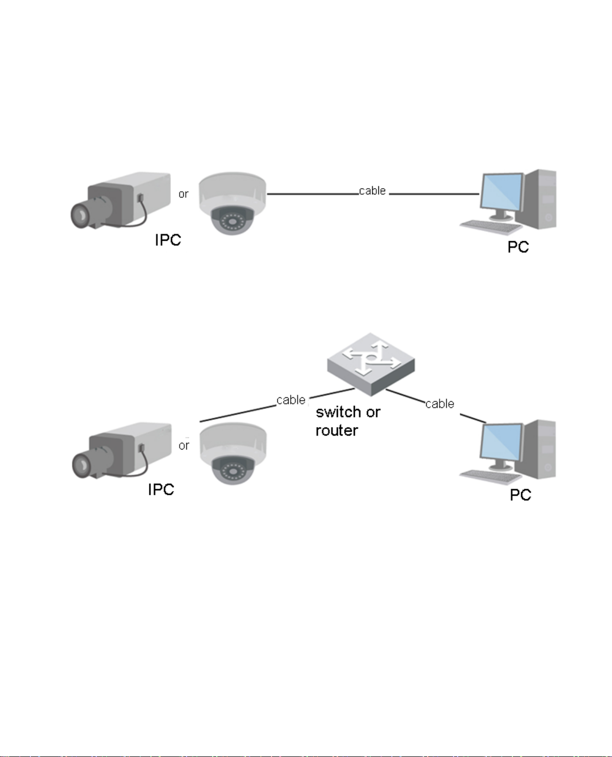
1.1 Network Connection
Network camera and PC c onnection mainly has two ways, see Figure 1- 1 and Figur e 1-2.
Figure 1- 1
Figure 1-2
Before you access networ k camera via the Internet, you need t o have its IP address. User can use
quick config tool to search IP of the network camera. Please refer t o Q uick Configuration Tool man ual.
1.2 Log in
It needs to install WEB plu g-in when you use WEB client for t he first time, the exact operation steps are
shown as follows:
Open IE and input networ k camera address in the address bar. (The factory default IP address is DHCP
mode).
Page 6
2
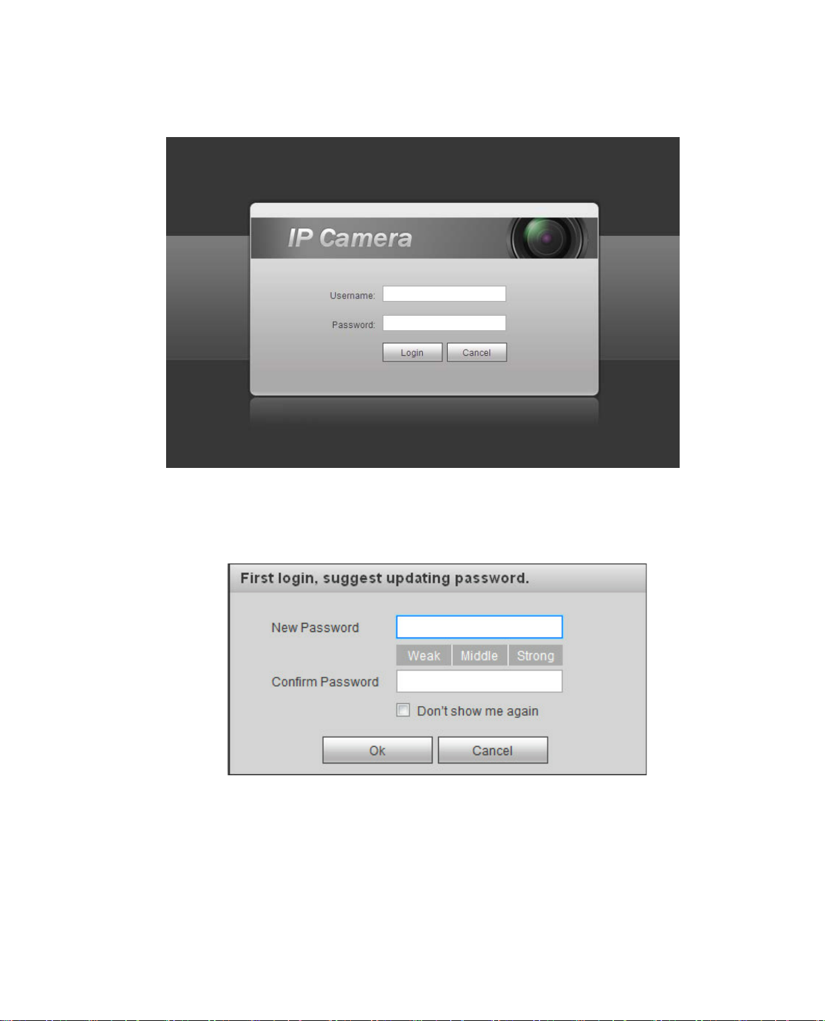
After successful connection, the log in interface is shown as in Fig ur e 1-3; input your user name and
password. Default factory usernam e is admin and password is admin.
Figure 1-3
The system will display “Modify Pas swo rd” prompt box for your first login, users need to modify the
password and save it properly.
Figure 1-4
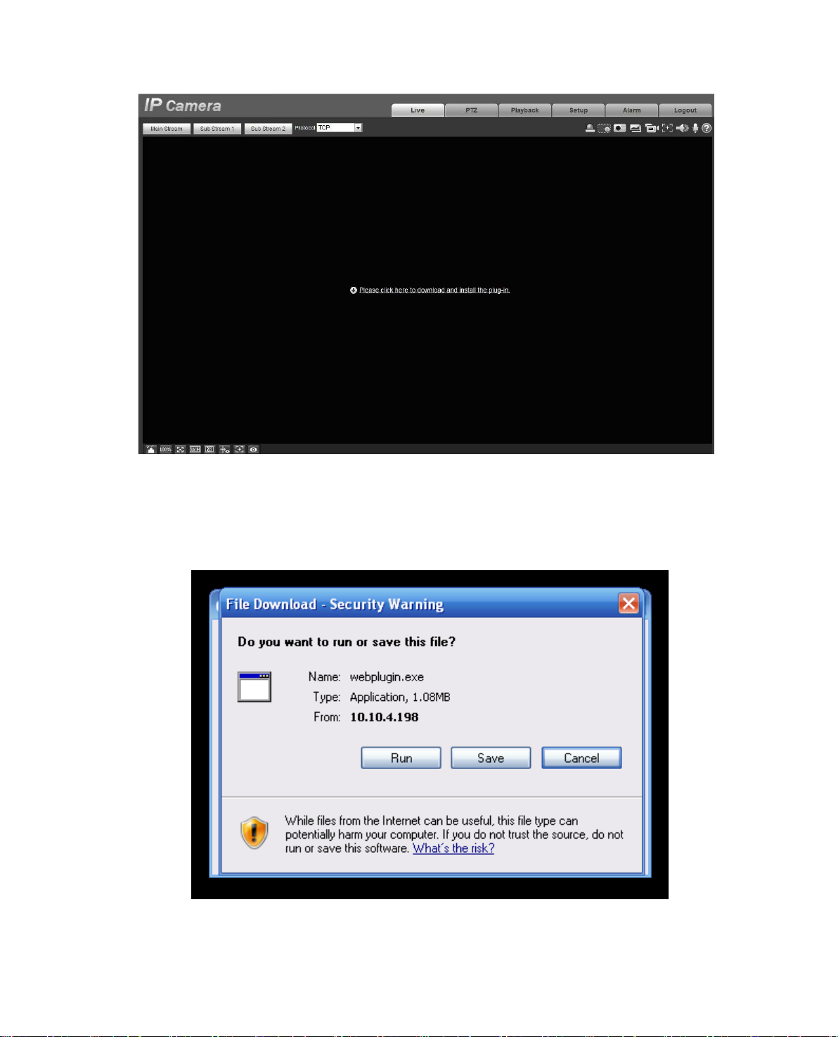
After successful login, you may see the interface s hown as in Figure 1-5.
Page 7
3
Figure 1-5
Click on “Please click here to download and install the pl ug-in”. The system pops up warning information
to ask you whether run or save t his pl ug-in. See Figure 1-6.
Figure 1-6
Page 8
4
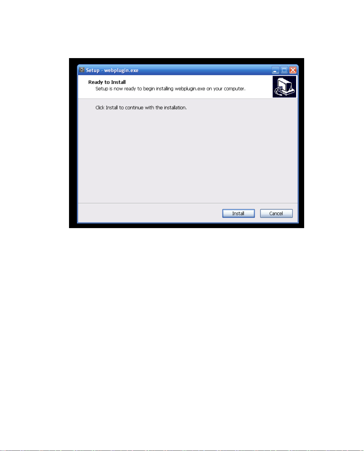
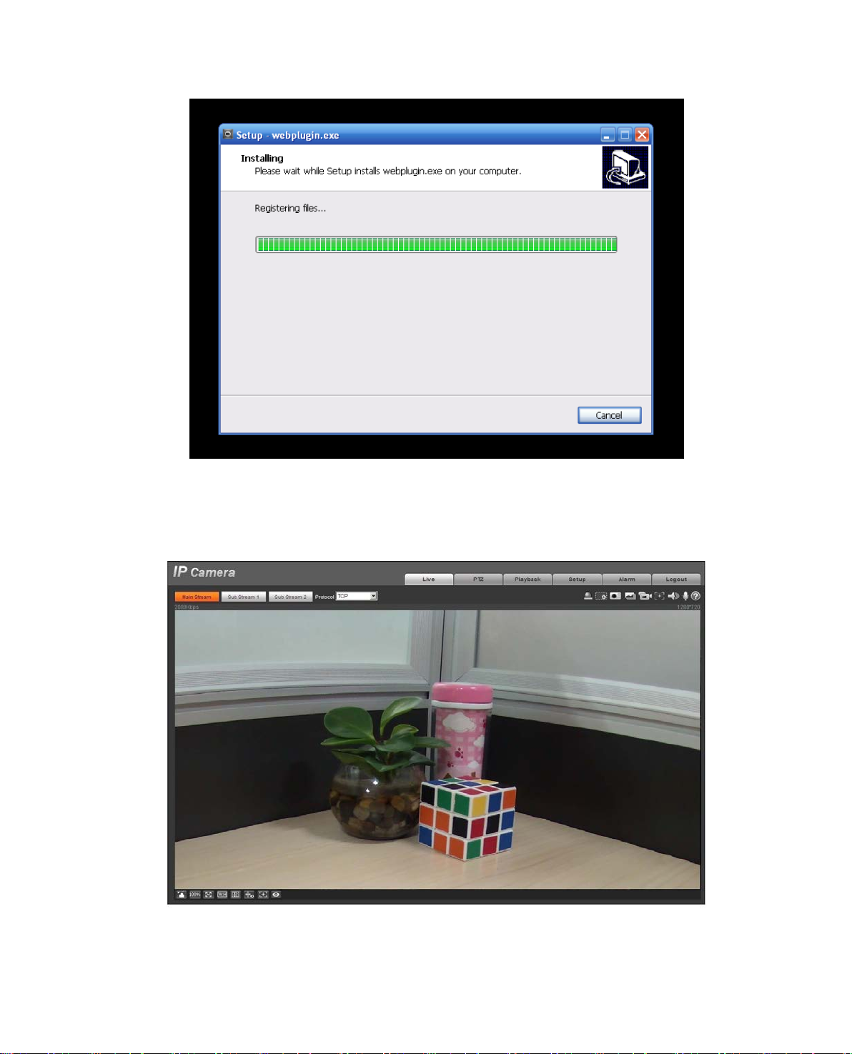
You must either run or save the file to local and install it. Fol low t he following steps. Click on run, you
will see Figure 1-7and Figur e 1-8.
Figure 1-7
Page 9
5
Figure 1-8
When plug-in installation complet es , t he installation page closes aut omatically. The web-en d will refresh
automatically, and then y ou can view video captured by the camera.
Figure 1-9
Page 10
6
2 3 1
4
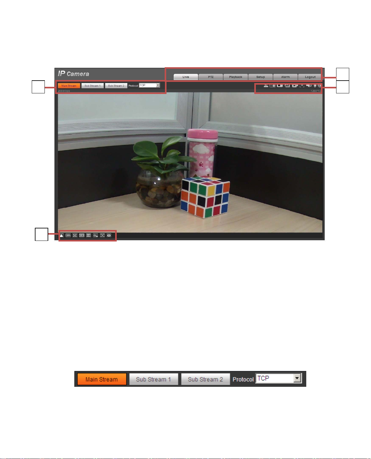
2 Live
After you logged in, you c an s ee t he live monitor window. See Figure 2-1.
Figure 2-1
There are four sections:
Section 1: Encode setup bar
Section 2: System menu
Section 3: Window function option bar
Section 4: Window adjust bar
2.1 Encode Setup
Note: Some series don’t suppor t triple code stream.
The encode setup interfac e is shown as in Figure 2-2.
Figure 2-2
Please refer to the following sheet for detailed information.
Page 11
7
Streaming media protocol connection, under ma in stream config,
monitor video or not. Generally for storage and monitor.
Streaming media protocol connection, under sub st r eam 1
insufficient, it substitute s ma in st r eam for monitoring.
Streaming media protocol connection, under sub st r eam 2
insufficient, it substitutes main stream for monitoring.
You can select stream media prot ocol from the dropdown l ist .
There are three options: TCP/UDP/Multicast
It shows if there is any alarm outp ut , status description is as
Click on the button to force alarm to be on or off.
1 2 3 4 5 6 7 8 9
Parameter Function
Main stream
Sub (Extra)
stream 1
Sub (Extra)
stream 2
Protocol
config, monitor video or not. When networ k ba ndw idth is
config, monitor video or not . When network bandwidth is
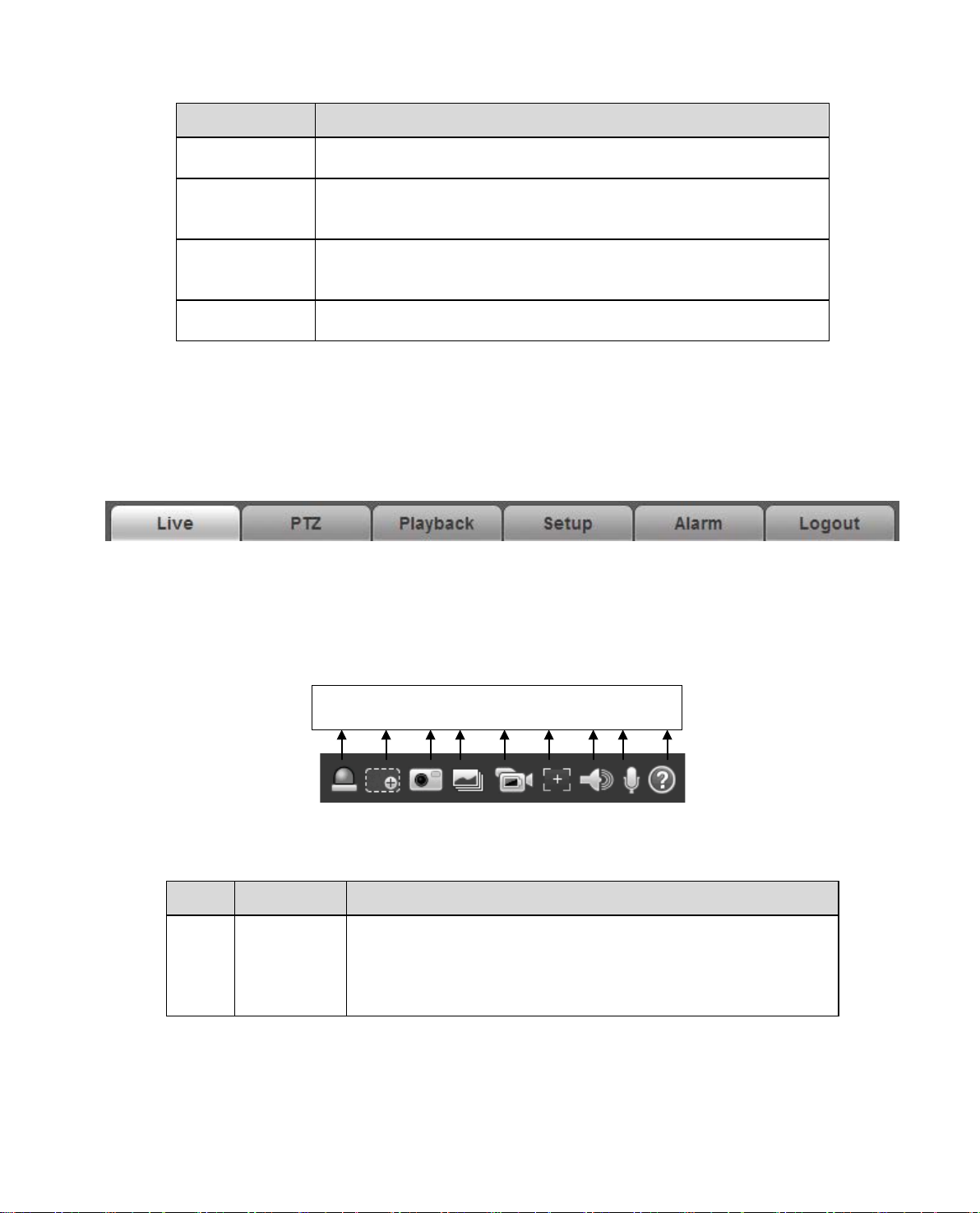
2.2 System Menu
System menu is shown as in Figure 2-3.
Please refer to chapter 2 Live, chapter 3 PTZ, ch apter 4 Playback, chapter 5 Setup, chapter 6 Alar m,
chapter 7 Log out for detailed information.
Figure 2-3
2.3 Video Window Function Opti on
The interface is shown as below . See Figure 2-4.
Figure 2-4
Please refer to the following sheet for detailed information.
SN Parameter Function
1
Alarm
output
follows:
Red: means there is alarm output.
Grey: means alarm is over.
Page 12
8
When the video is in the or iginal status, click it you can
zoom in/out the video size.
Click on the button to snapshot, save picture to path in Ch
Click it, system can snap at 1f/s. All images are saved to path
in Ch 5.1.2.5.
Turn on or off audio when y ou ar e mo nitoring.
2 Zoom in
3 Snapshot
4 Triple snap
5 Record
6 Easy focus
select any zone to zoom in. I n t he non-original status,
you can drag the zoom-in z one in specified range. Right
click mouse to restore previous status.
Click it; you can use the midd le butt on of the mouse to
5.1.2.5.
Click it, system can record. All images are saved to path in Ch
5.1.2.5.
Click it, you can see there are two parameters on the preview
video:AF Peak and AF Max.
AF Peak: It is to display the video definition during the focus
process.
AF Max: It is the most suitable value for the video definition.
The close the AF Peak and AF Ma x is, t he bet ter the focus
effect is.
7
8
9 Help Click it to open help file.
Audio
output
Bidirectional
talk
Click it to start or end bidirectional talk.
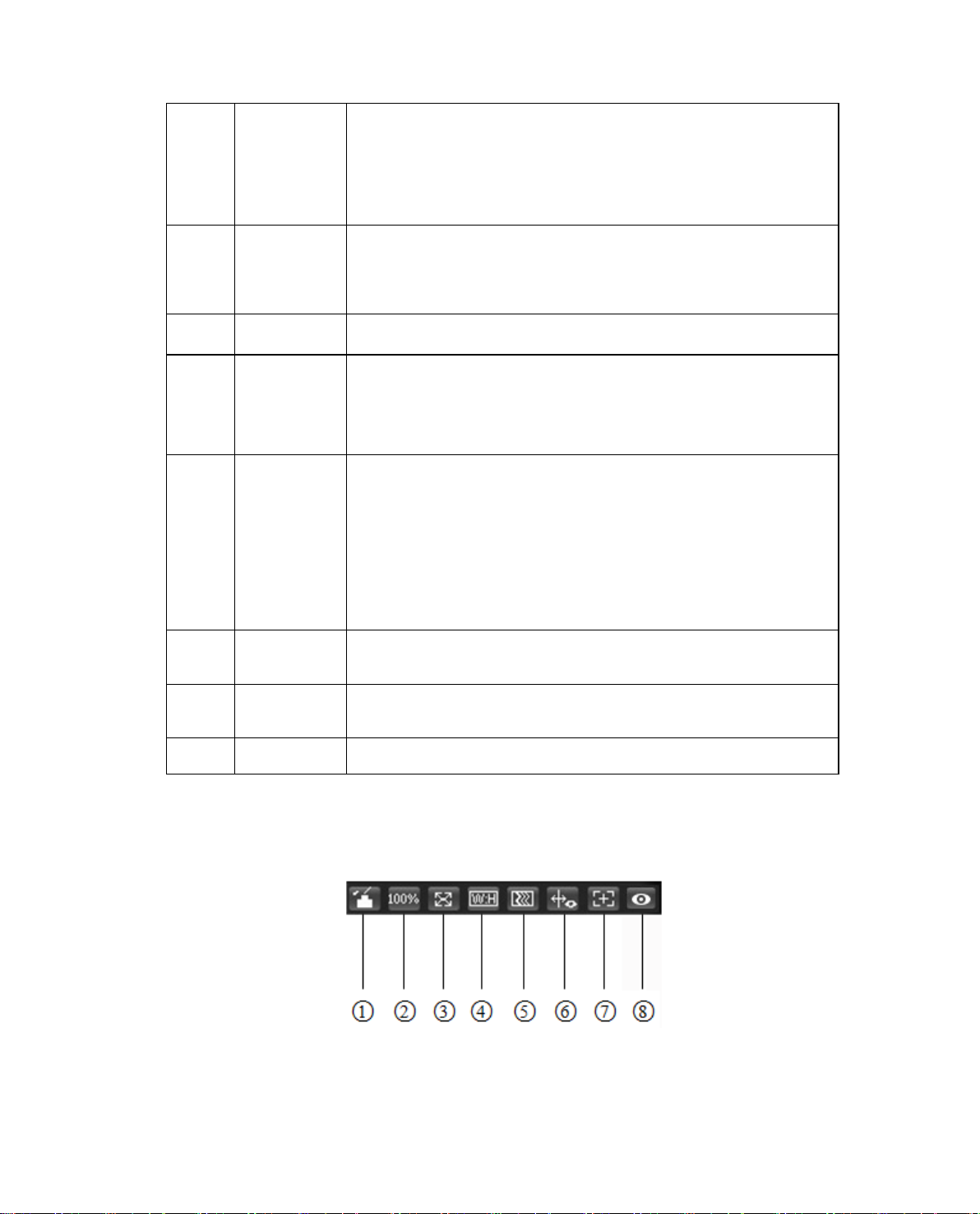
2.4 Video Window Setup
The interface is shown as in Figure 2-5.
Figure 2-5
Page 13
9
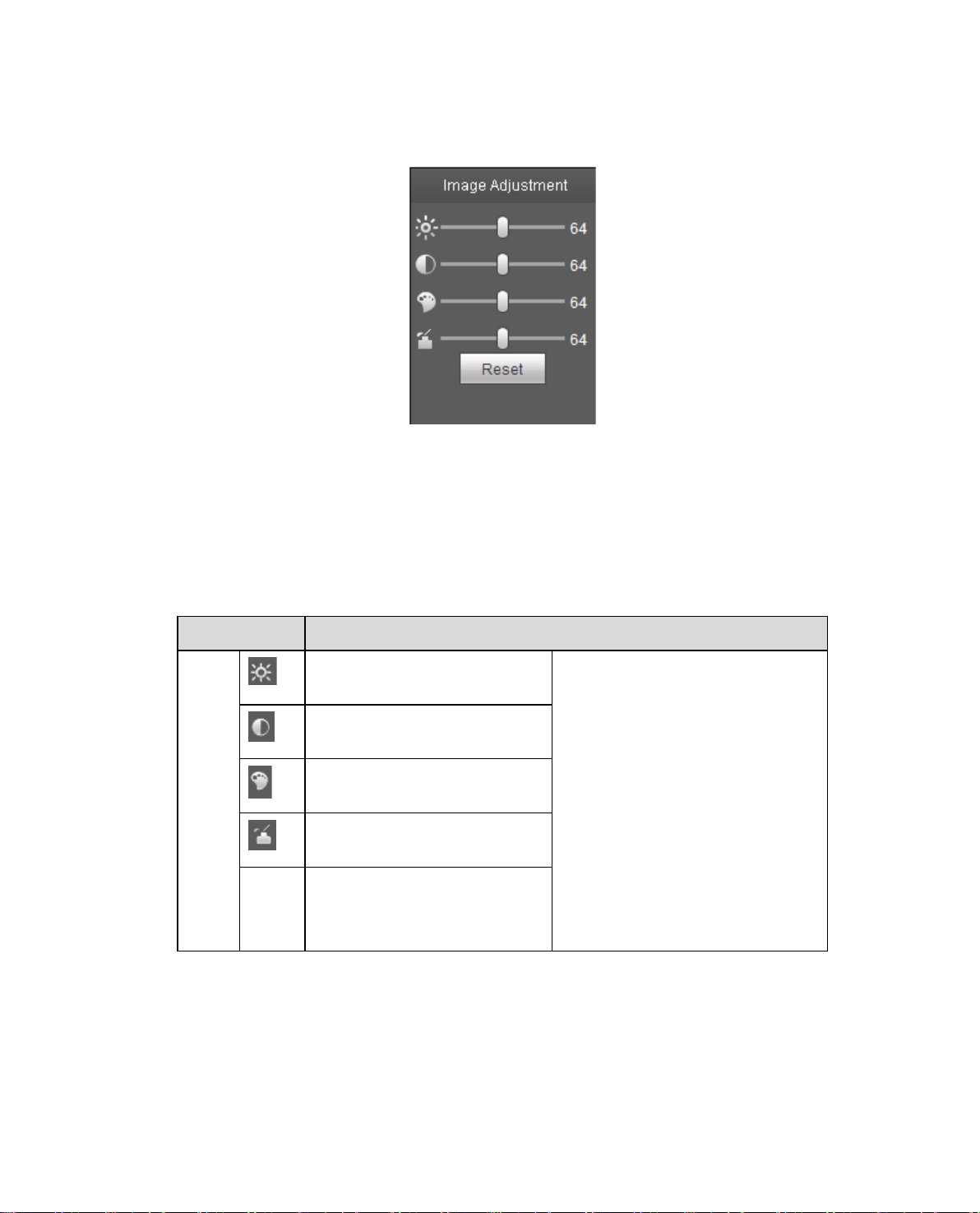
2.4.1 Image Adjustment
See Figure 2-6 for image adjust ment.
Figure 2-6
Click this button to display/hide image control interfa ce. Cl ic k it to open p ict ur e setup interface. This
interface is on the top right pane.
Please refer to the following sheet for detailed information.
Parameter Function
Video
setup
Reset
It is to adjust monitor video
brightness.
It is to adjust monitor video
contrastness.
It is to adjust monitor video
hue.
It is to adjust monitor video
saturation.
Restore brightness,
contrastness saturation and
hue to system default setup.
Note:
All the operations here apply
to WEB end only.
Please go to Setup-
>Camera->Conditions to
adjust corresponding items.
2.4.2 Original Size
Click this button to go to original size. It is to display the actual size of the video strea m. I t depends on
the resolution of the bit str eam.
Page 14
10
2.4.3 Full Screen
Click it to go to full-screen mod e. Double click the mouse or click the Esc button to exit the full scr een.
2.4.4 Width and Height Ratio
Click it to restore original ratio or suitable window.
2.4.5 Fluency Adjustment
There are three levels of fluency for you to select (real-time, nor m al, f luent). The default is normal.
2.4.6 Rules Info
Click the button, preview i ma ge w i ll d isplay intelligent rules a ft er enabling; it is “enable” by default.
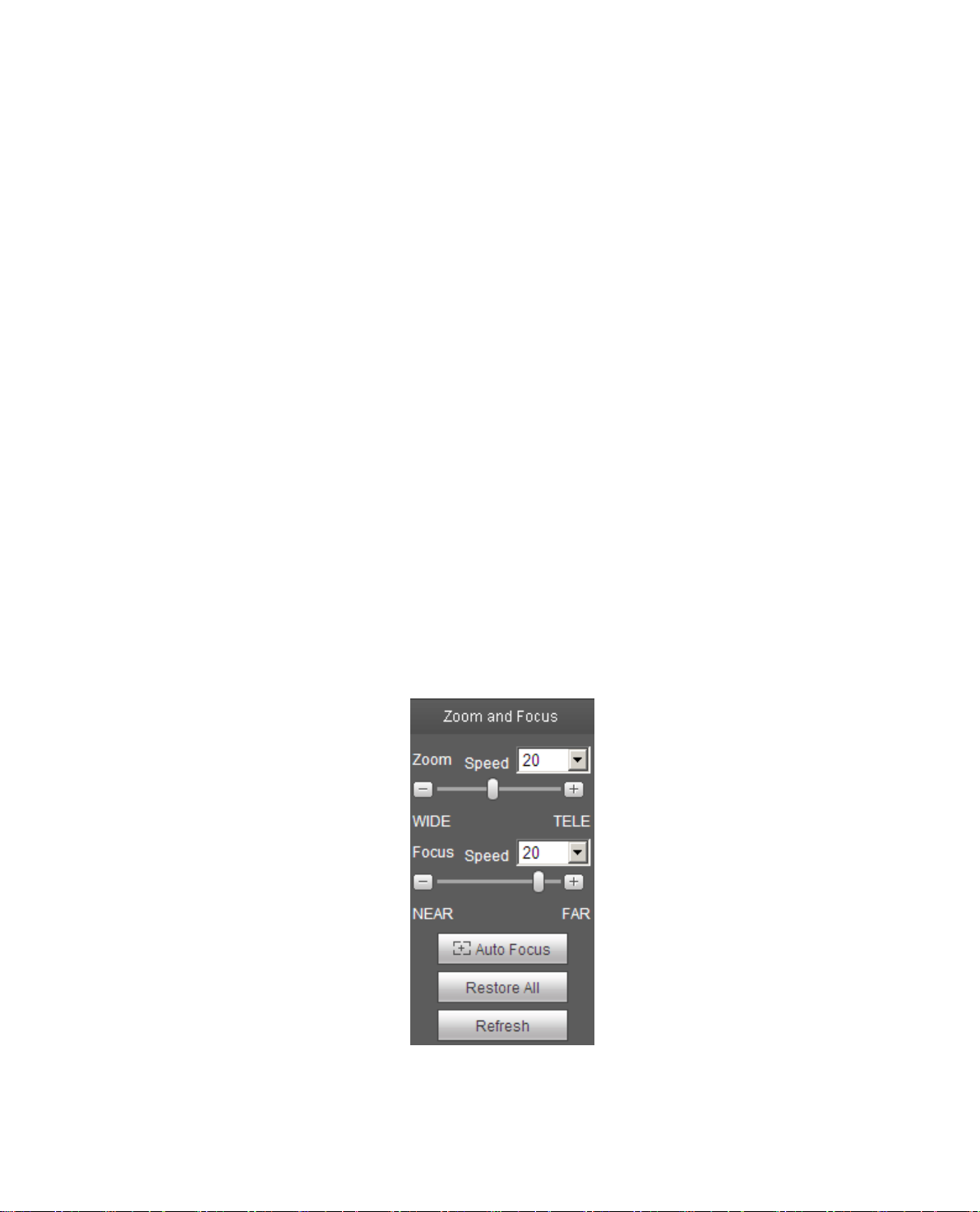
2.4.7 Focus zoom
Click this button and the focus z ooming interface appears on t he right of preview interface, as shown in
Figure 2-7, click left mouse button to adjust focus zooming configuration.
Note:
· The product series which support motorized zoom, synchronous focus and back foc us have this
button.
· Auto-focus after zoom and focus adjustment.
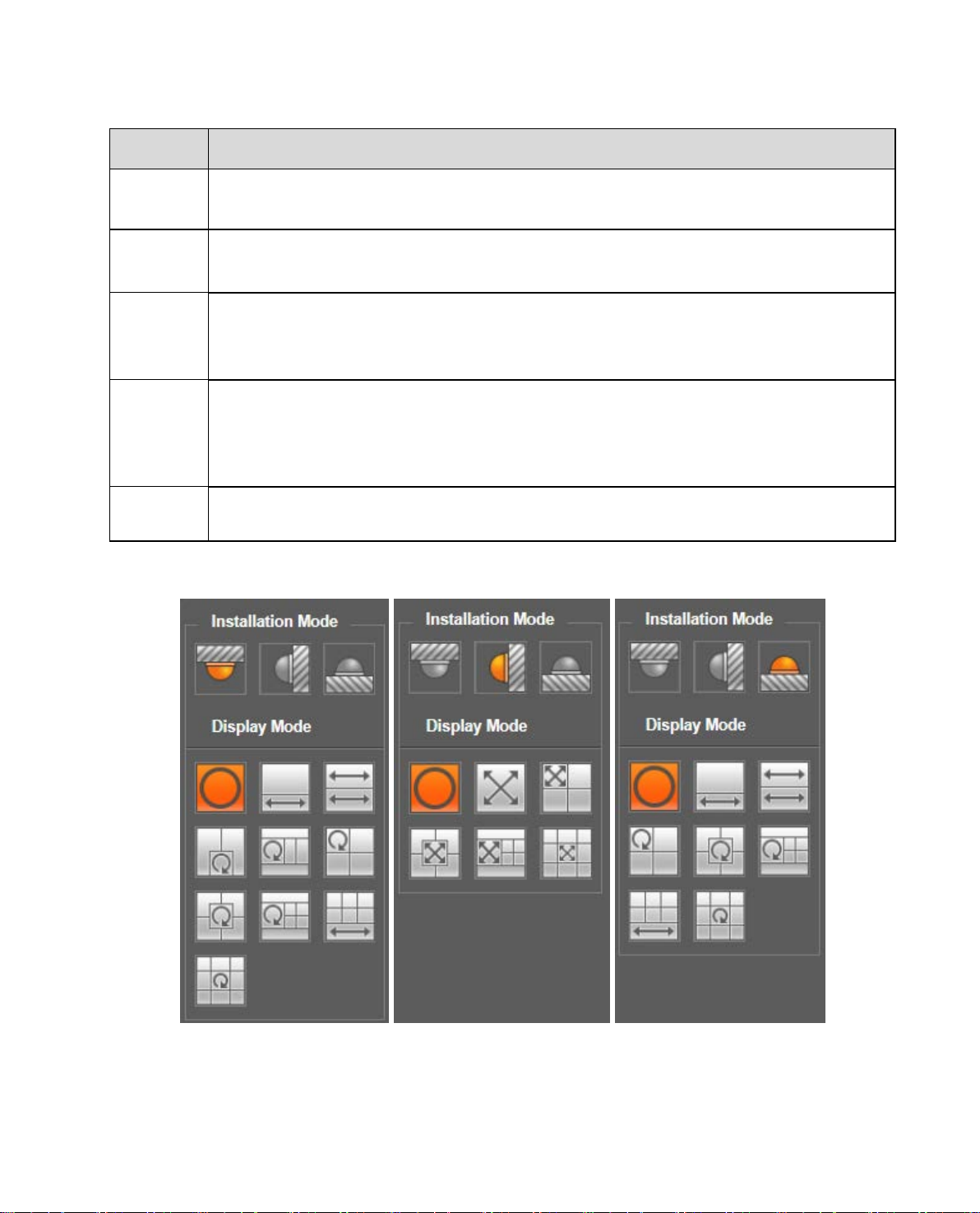
2.4.8 Fisheye
Click the button, installation mode and display mode int er fa ce will show up on the right of the pr eview
interface, see Figure 2-8, single click to switch different inst allation mode and display mode, default is
enable.
Note: Only supported by fisheye devices.
Figure 2-7
Page 15
11
drag slider of lens and zoom focus after hardware zoom
Parameter Function
Zoom
Focus
Autofocus
Reset
Refresh
Adjust the focal length of the lens by clicking or long pressi ng “ + ” “ -”buttons.
Step length is used to adjust the length of o ne st ep with one click.
Adjust the sharpness of the lens by clicking or long pressing“+ ” 、“-” buttons.
Step length is used to adjust t he len gt h of one step with one click.
Click to adjust the image definition automatically.
Note:
Other lens operations are not all ow ed during the process of auto-focus.
Reset the lens to zero position to e li m inate the accumulativ e er r or of le ns.
Note:
Please reset when the image adjustment is not clear or operating zoom focus many
times.
Synchronize the location of
focusing.
In-ceiling Mount Wall Mount Ground Mount
Figure 2-8
Page 16

12
It represents the display mode of the current image (default supports original
g to different
and the subbox in the
expanded rectangular panorama support zoom and
movement, for the expanded rectangular panorama
Two related 180° expanded rectangular pictures, two
subwindows form 360° panorama anytime, which is
also called “dual panorama”. Two expanded
rectangular pictures both support left and right
linked by
eachother.
Original image + 2 independent sub images, both the
sub image and the subbox in the original image
support zoom and movement. The original image also
supports changing starting point by rotation (no such
display mode for ground inst al lation).
Original image + 2 independent sub images, both the
sub image and the subbox in the original image
support zoom and movement. The original image also
supports changing starting point by rotation
Original image + 4 independent sub images, both the
sub image and the subbox in the original image
support zoom and movement. The original image also
supports changing starting point by rotation
360°expanded rectangular panorama +6 independent
expanded rectangular panorama support zoom and
movement, for the expanded rectangular panorama
also supports left and righ t starting point movement.
parameter Note
Installation Mode Three modes which are c eiling mount, wall mount and grou nd mount.
image mode), the display modes may be different accordin
installation modes. It is shown as fo l lows:
Ceiling: 1P+1、2P、1+2、1+3、1+4、1P+6、1+8。
Display Mode
Wall: 1P、1P+3、1P+4、1P+8。
Ground: 1P+1、2P、1+3、1+4、1P+6、1+8。
Note:
The default displays original image mode when swit ching installation mode.
In-ceiling/Wall/Ground
In-ceiling/Ground
image
1P+1
2P
1+3
Original
1+2
It menas the original imag e w ithout de-warpping
360°expanded rectangular panorama + independent
sub image, the sub image
also supports left and righ t starting point movement.
movement starting point, which are also
1+4
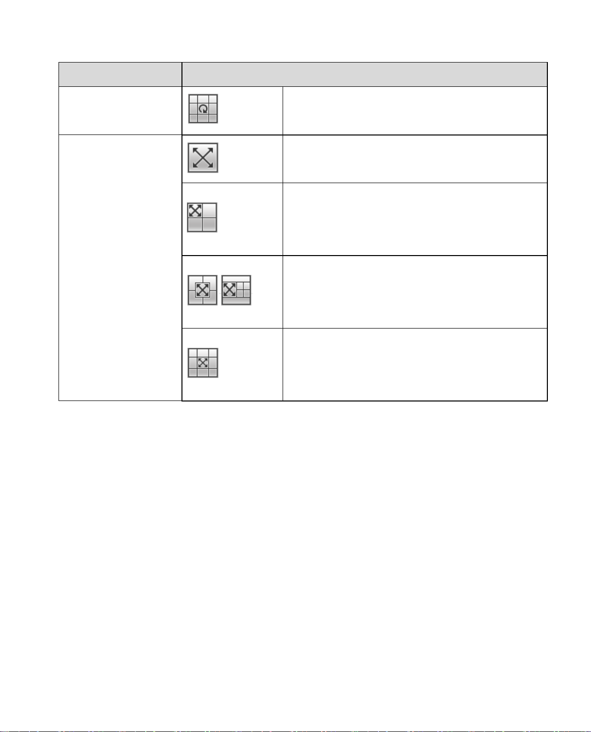
1P+6
sub image, both the sub image and t he subbox in the
Page 17
13
Original image + 8 independent sub images, both the
he original image
support zoom and movement. The original image also
supports changing starting point by rotation
expanded rectangular
panorama, which supports up and down movement
180° expanded rectangular panorama+3 independent
sub images, both the sub images and the sub box in
the expanded rectangular panorama support zoom
and movement, expanded rectangular panorama
supports up and down movement and changes vertical
angle of view.
180° expanded rectangular panorama+4 independent
sub images, both the sub images and the sub box in
the expanded rectangular panorama support zoom
and movement, expanded rectangular panorama
angle of view.
180° expanded rectangular panorama+8 independent
sub images, both the sub images and the sub box in
the expanded rectangular panorama support zoom
and movement, expanded rectangular panorama
angle of view.
parameter Note
sub image and the subbox in t
1+8
From left to right 180°
Wall
1P
1P+3
1P+8
1P+4
and changes vertical ang l e of view.
supports up and down movement and changes vertical
supports up and down movement and changes vertical
Page 18
14
PTZ supports eight directions: left/right/up/d own/upper left/upper
right/bottom left/bottom right.
It controls rotation speed. The longer the step length, the higher the speed.
Step length control PTZ, zoom, focus and iris.
Use mouse to draw a box in monitoring video, PTZ will rotate and focus to
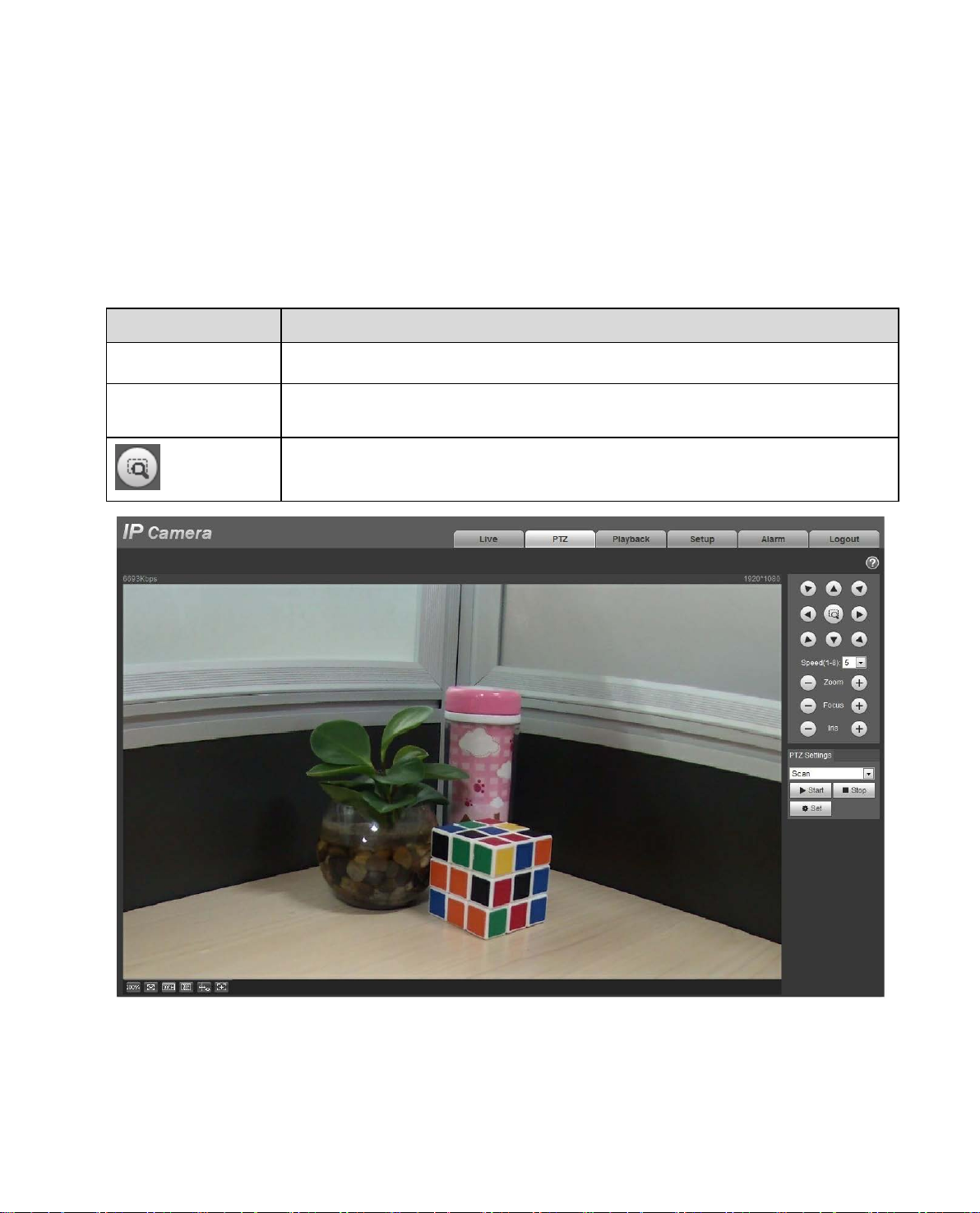
3 PTZ Control
Here you can view direction keys, speed, zoom, focus, iris, preset, tour, pan, scan, pattern, aux on, off
and PTZ setup button. See
Figure 3-1.
Note:
Before PTZ operation, please make sur e you have properly set PTZ proto col. (Please refer to Ch 5.5.3) .
Currently only ICIP Pxxx series product ca n support PTZ function.
Parameter Note
PTZ direction
Speed
Quick Position
quickly positioning.
Figure 3-1
Page 19
15
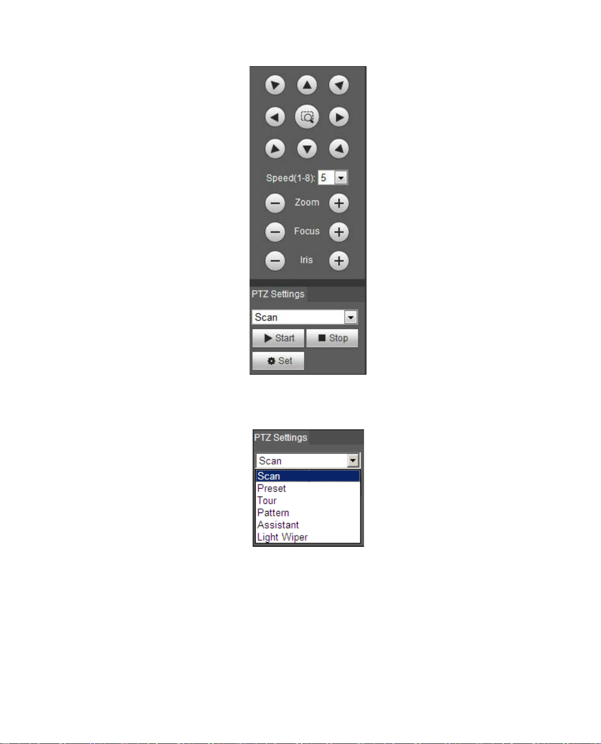
Figure 3-2
PTZ setting interface is shown as in Figure 3-3.
Here you can set scan, preset , t our , pat tern, assistant function and light and wiper plus view coordinate.
Figure 3-3
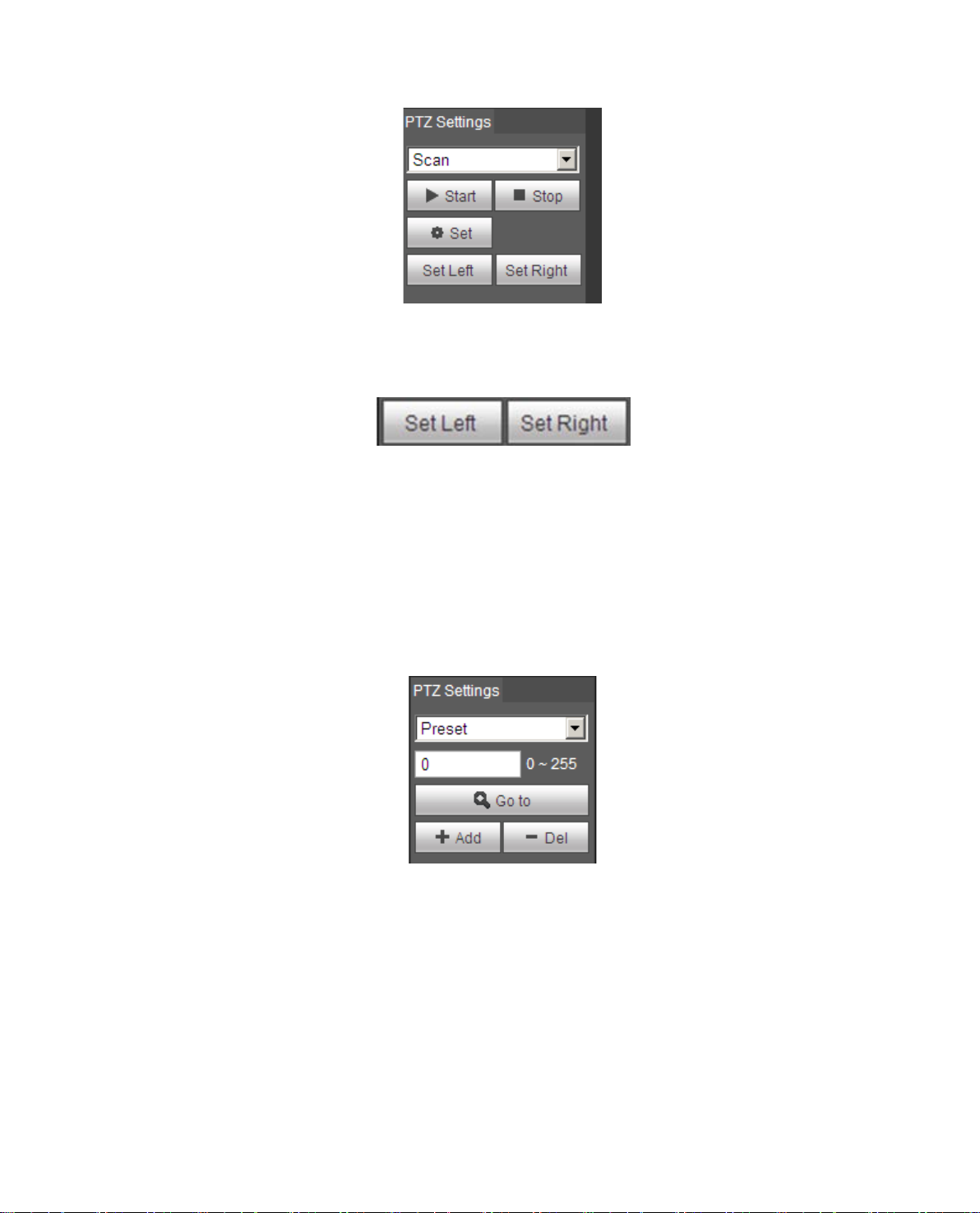
3.1 Scan
Scan interface is shown in Figure 3-4.
Page 20
16
Figure 3-4
Steps to scan are:
Step 1. Click on Set button, display icon.
Step 2. Move v ia direct ion key to select left, click on S et Left to set left border of camera
Step 3. Move v ia direct ion key to select right, clic k on Set Right to set right border of camera.
Step 4. Complete s can path setup.
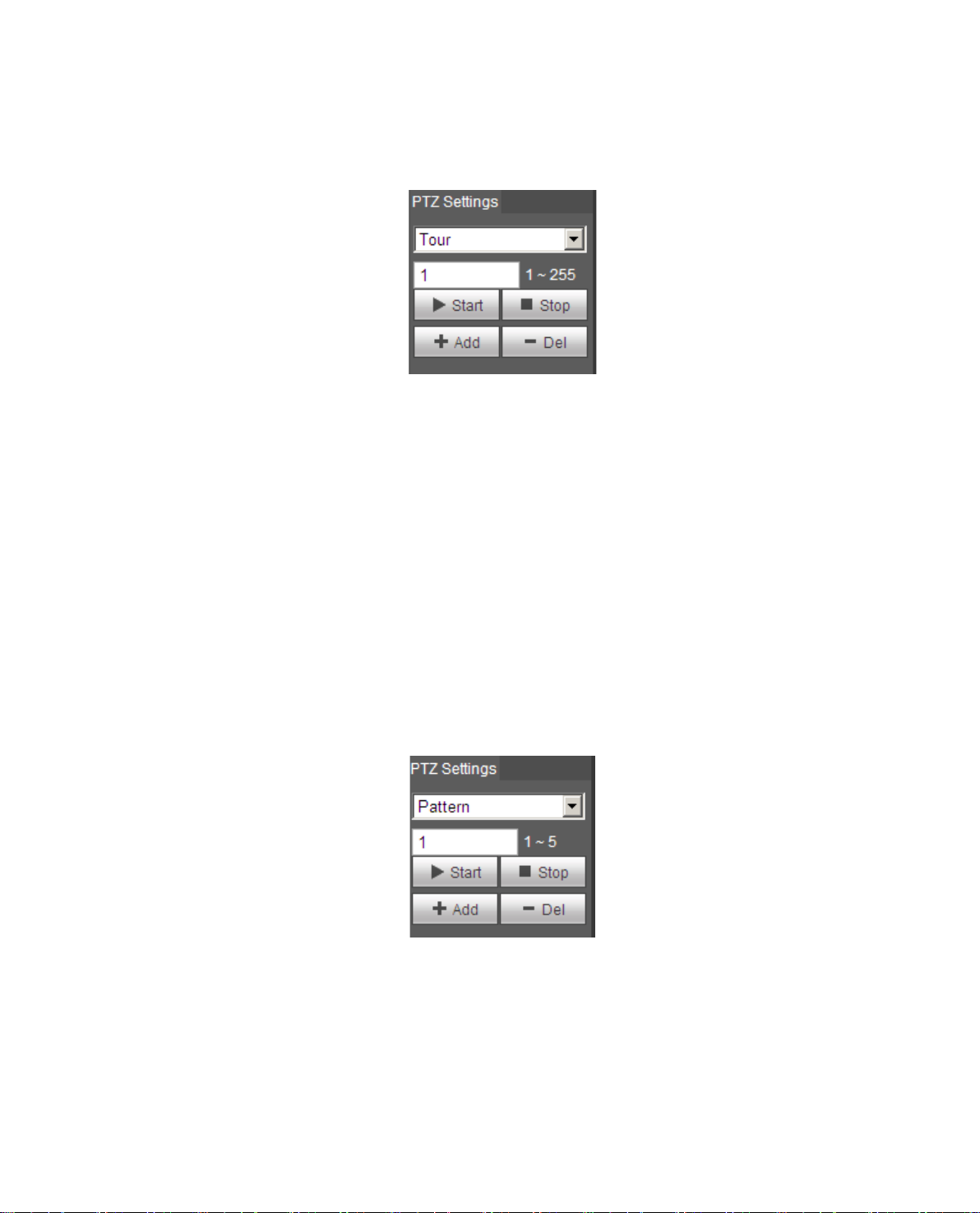
3.2 Preset
Preset interface is shown in Figure 3-5.
Figure 3-5
Steps to preset are:
Step 1. In preset box, in put pr eset value.
Step 2. Click on Go to, camera rotates t o pr eset position.
Step 3. Use direct ion key to rotate camera, and in pres et box input preset value.
Step 4. Click on Add t o add a pr eset. Range of preset relates t o PT Z pr ot ocol.
Page 21
17
3.3 Tour
Tour interface is shown in Fig ur e 3-6.
Figure 3-6
Steps to tour are:
Step 1. In tour box, input t our pat h value.
Step 2. Click on Add. Range of tour relates to PTZ pr ot oc ol.
Step 3. In preset box, input preset value.
Step 4. Click on Add as to add a preset in this tour. If clic k o n De l, it deletes this preset in tour.
Note:
You can add more than one preset here, or delete more than on e preset.
3.4 Pattern
Pattern interface is shown in Fi gure 3-7.
Figure 3-7
Steps to pattern are:
Step 1. In pattern box input pattern value, click on Add.
Step 2. Click on Start , to zoom, focus, iris or move.
Step 3. Click on Stop to finish setup of one pattern.
Page 22
18
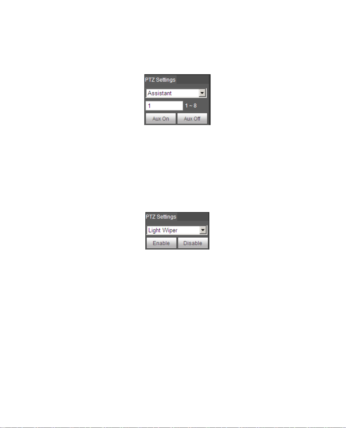
3.5 Assistant
Assistant interface is sho w n in Figure 3-8.
Figure 3-8
Steps to assistant are:
Step 1. In assistant box input assistant value.
Step 2. Click on Aux On to turn on aux function.
Click on Aux off to turn off aux function.
3.6 Light Wiper
Light wiper interface is shown in Figure 3-9.
Figure 3-9
Steps to light wiper are:
Click on Enable to enable light wiper function.
Click on Disable to disable light wiper function.
Page 23
19
2 3 4
1 6 5
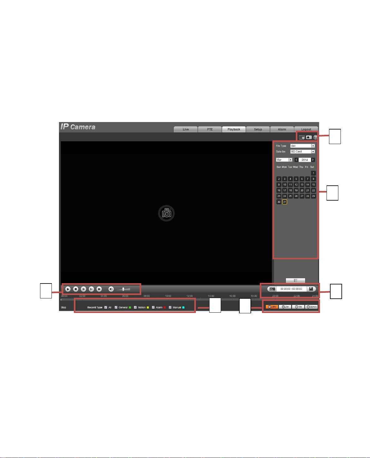
4 Playback
Web client playback supports video pl ayback and picture playback.
Note:
Before playback, user sha ll set storage management as in Ch 5.4.
4.1 Playback
The playback interface is shown as in Figure 4- 1.
Figure 4- 1
There are four sections:
Section 1: Function of play
Section 2: Playback file
Section 3: Play time cut
Section 4: Record type
Section 5: Progress bar
Section 6: Assistant function
Page 24
20
When you see this button, it means pause or not played record. Click on this
Play by
When this button displays, it means audio is silent. Click on this button to switch
Click this button and fisheye device can adjust display mode according to
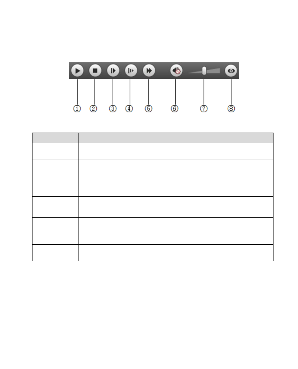
4.1.1 Function of Play
The function of play is show n as in Figure 4- 2.
Parameter Function
Figure 4- 2
① Play
② Stop Click this button to stop playing.
③
frame
④ Slow Click on this button to play slow ly .
⑤ Quick Click on this button to play quickly.
⑥ Silent
⑦ Volume Click on left mouse to adjust volume.
⑧ Fisheye
button, switch to normal play status.
Click on this button to go to next frame.
Note:
You shall pause record when y ou us e t hi s function.
back to normal.
different installation mod e during the process of play back.
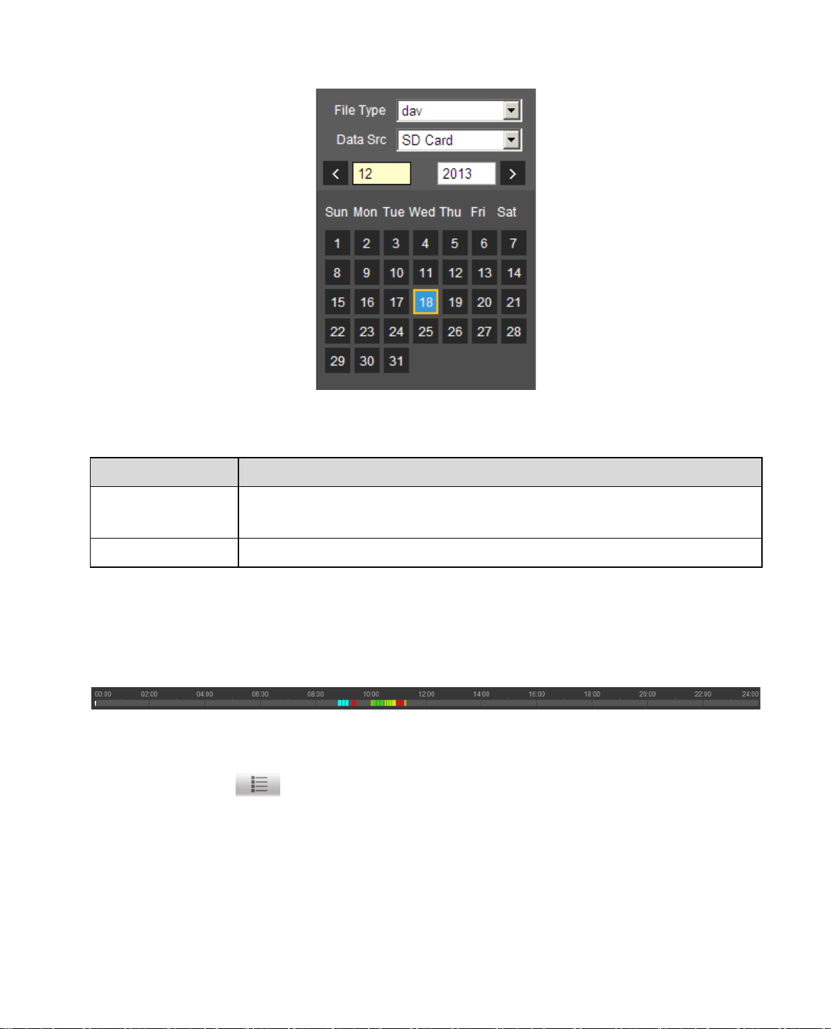
4.1.2 Playback File
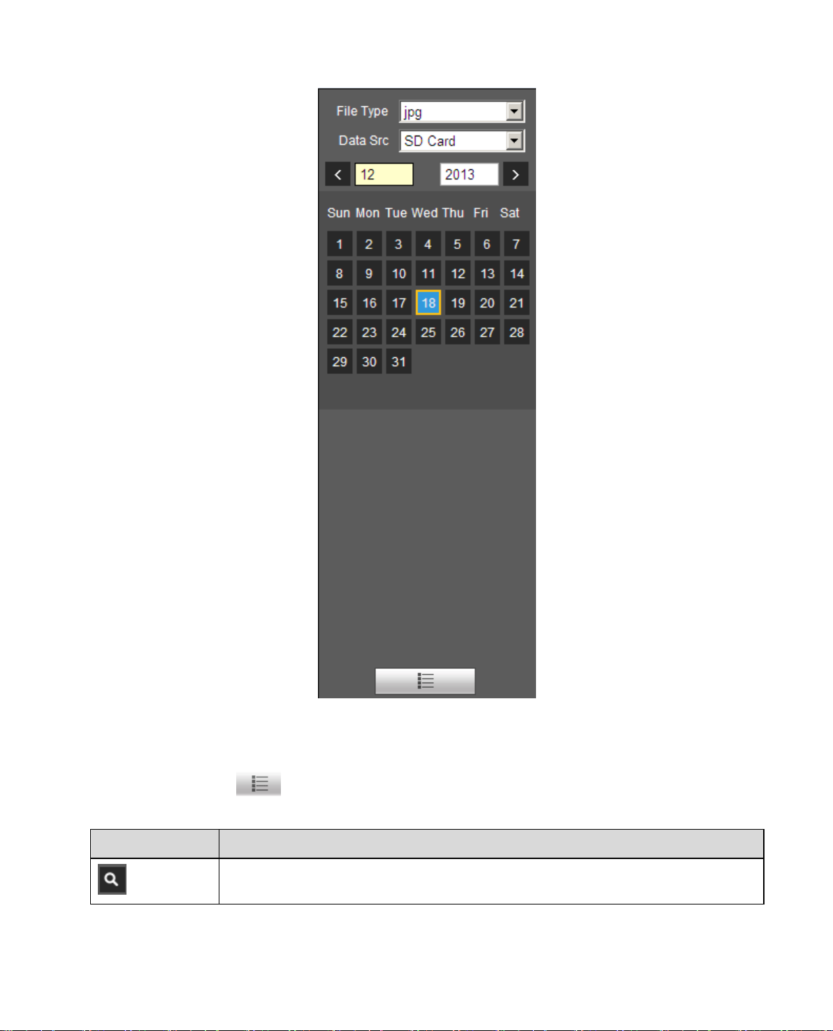
In calendar, blue date represent s data currently has video recor d or snapshot. See Figure 4-3.
Page 25
21
Parameter Function
Figure 4-3
File Type
Data Source Default is S D card.
Step 1. Click on data in blue, time axis displays record fi le p r ogr es s bar in color. While, gr een r epr esents
normal record, yellow repr esent s motion detect record, r ed r epr esents alarm record, and blu e
represents manual recor d.
Step 2. Click on certain time on progress bar, playback starts from this time. See
Select “dav”, as video playback.
Select “jpg” as picture playback.
Figure 4- 4.
Figure 4- 4
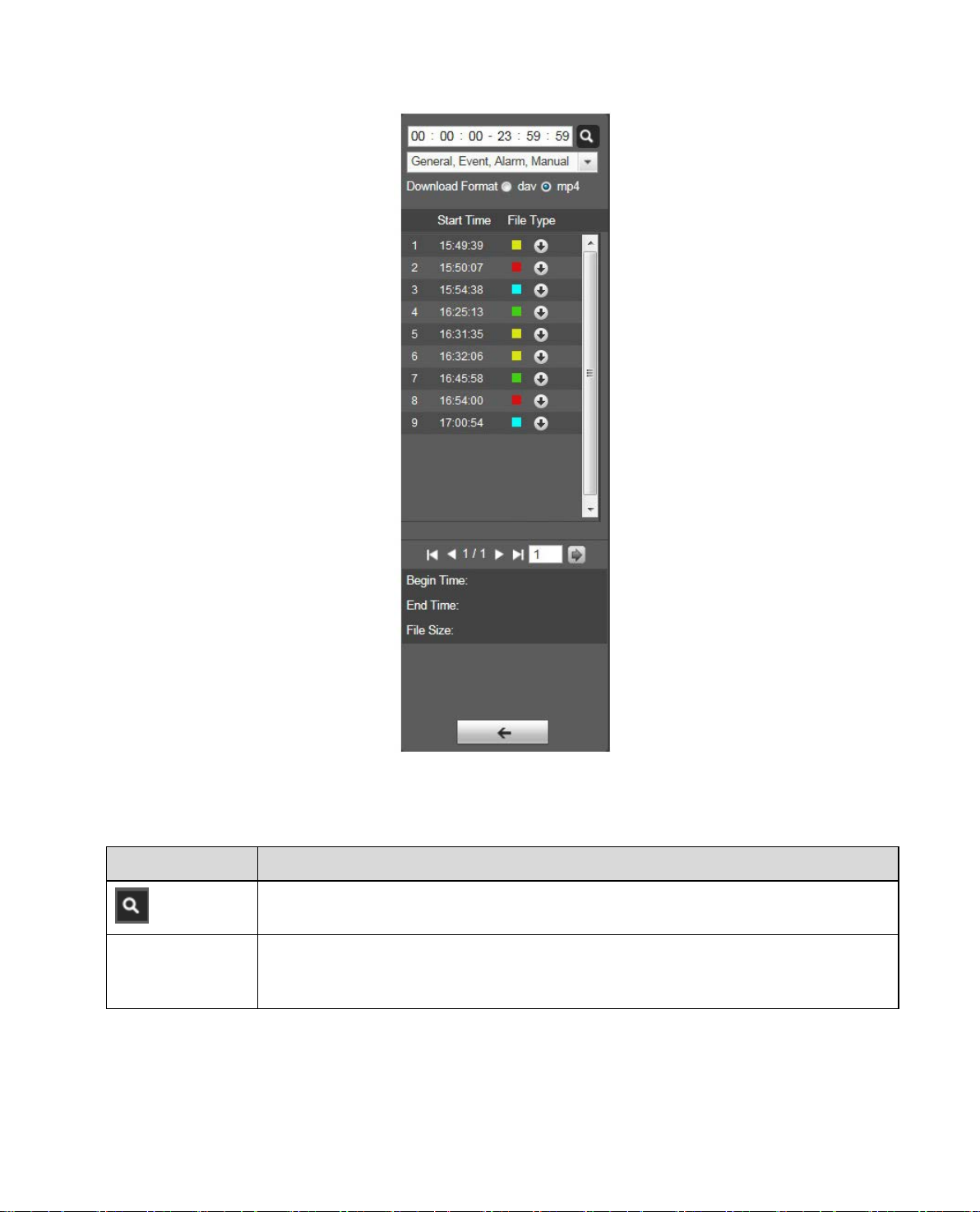
Step 3. Clic k on file list
Step 4. Double click on file in list, playback this fi le an d display file size, start time and end time.
See Figure 4-5.
, select date file will be displayed in list.
Page 26
22
Parameter Function
Search
Record
Download
Format
It means records within searched start time and end tim e on t he dat e.
There are two formats: dav , mp4.
Figure 4-5
Page 27
23
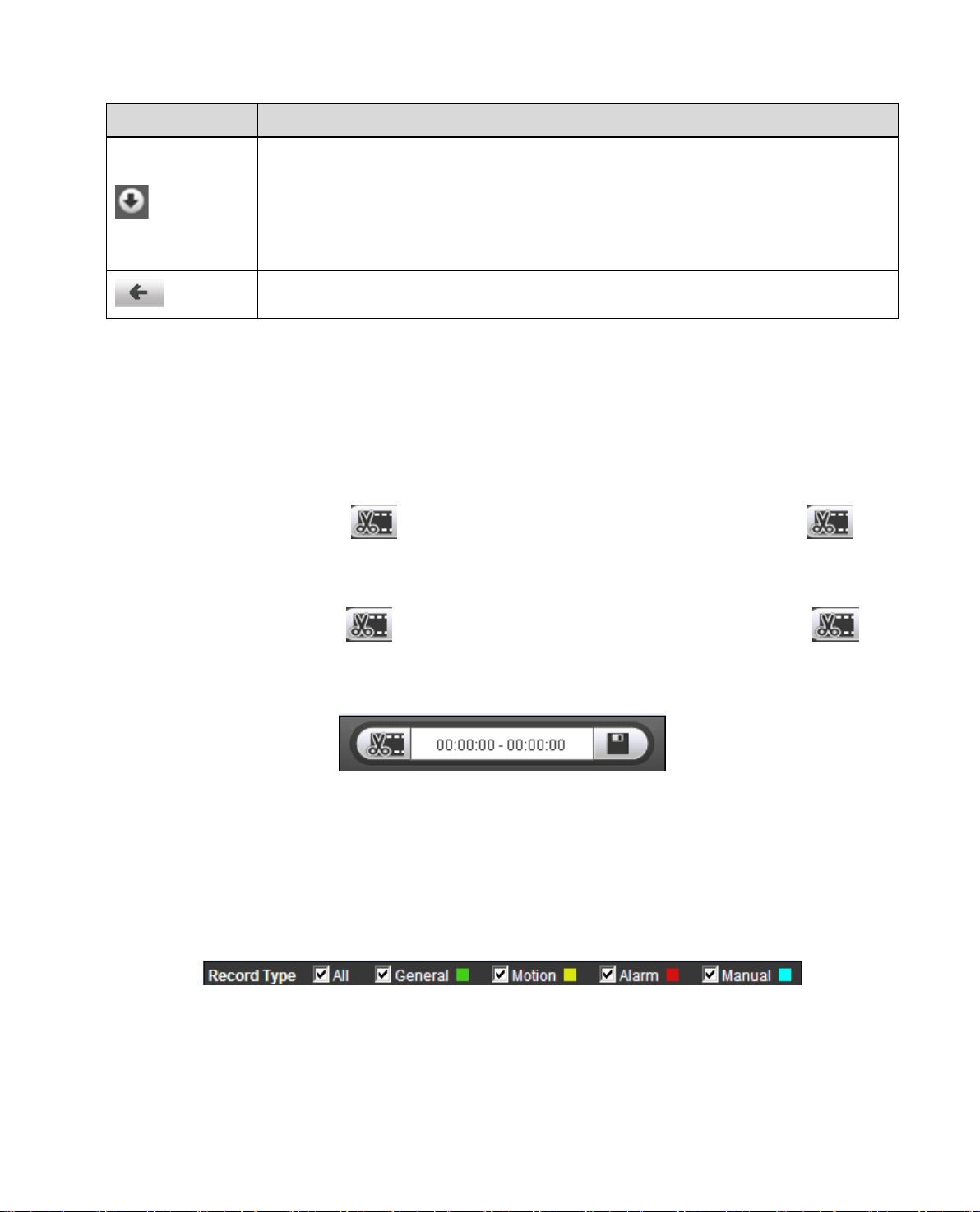
Record type is “mp4”, click on download button and download file to path in
Parameter Function
Record type is “dav”, click on dow nl oad button to download file t o local.
Download
Ch 5.1.2.5.
Note:
System does not support dow nl oad and playback of MP4 file.
Back
Click on back button to go to c alen dar int erface.
4.1.3 Playback Cut
Note:
Playback cut function will aut omatically pause playing recor d as playback cut and play back cannot be at
the same time.
Step 1. Click on start time to cut on time axis. This ti me mu st be within progress bar range.
Step 2. Move mouse t o c ut ic on
finish cutting.
Step 3. Click on playback cut end time on time axis. This time must be within progress bar range.
Step 4. Move mouse t o c ut icon
finish cutting.
Step 5. Click on Save but ton to save file cut to path in Ch 5.1.2.5. See Figure 4- 6.
. You will be ask to select start t ime. Clic k on c ur i con as
, you will be asked to select end t i me. Click on cut icon as
Figure 4- 6
4.1.4 Record Type
After checking record file type, only selected file w i ll be displayed in progress bar and file list. Users can
also select the record type to be displayed via the dropdown box which is above the file list. See Figure
4- 7.
Figure 4- 7
4.1.5 Progress Bar
Page 28
24
if is in original size, user can
zoom in any area, If it is not in its original size, click on mouse to
ck on this button, you can snapshot video under playback status.
3
Snapshot type bar
Parameter Function
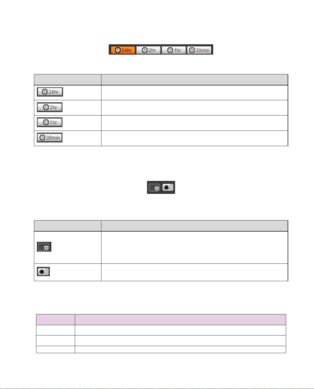
Figure 4- 8
24 hours
2 hours
1 hour
30 min
Click on it, m eans video in past 24 hours.
Click on it, means video in past 2 hours.
Click on it, means video in past 1 hour.
Click on it, means video in past 30 min.
4.1.6 Assistant Function
Video playback assistant f unction is shown in Figure 4- 9.
Figure 4- 9
Parameter Function
Click on it, video in playback status
Zoom in
Snapshot
restore its original size.
Click on this button, you can scr oll to zoom in.
Cli
Snapshot will be saved to path in Ch 5.1.2.5.
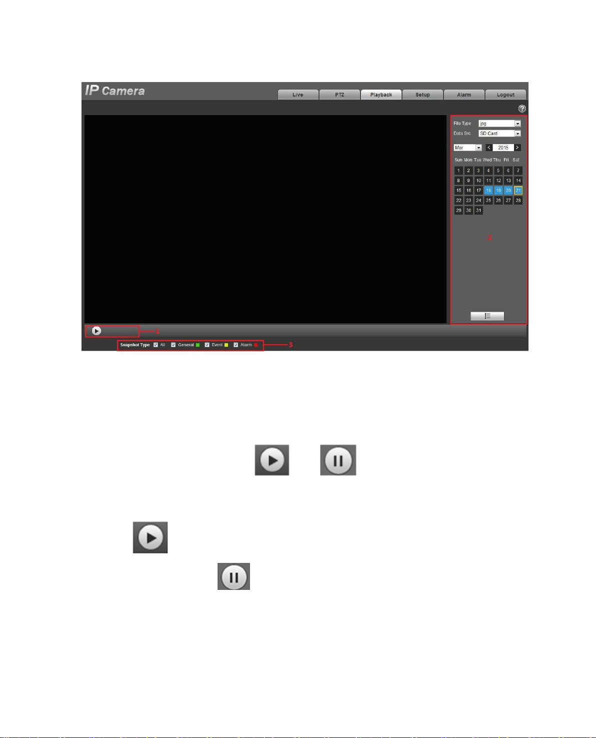
4.2 Picture Playback
Web client picture playba ck interface has the following t hr ee f unctions:
Parameter Function
1 Play function bar
2 Playback file bar
Page 29
25
See Figure 4-10.
Figure 4-10
4.2.1 Play
Figure 4-11
Default ico n is and it means pause or not p layed picture. Click on play but t on t o switch to
normal play status. Icon b ecome
Click on it to pause.
4.2.2 Playback File
Page 30
26
Figure 4-12
Step 1. Clic k on file list , select snapshot file of th e dat e.
Step 2. Double click on file in list, to play this snapshot.
Parameter Function
Search
It means all snapshot files within the start time and end ti me o f selected date.
Page 31

27
Parameter Function
Download
Back
Click on download button t o dow nload snapshot file to local.
Click on back button to return t o c ale ndar interface and re-select time.
Figure 4-13
4.2.3 Snapshot Type
Page 32

28
After checking snapshot file type, in file list only display file of selected type. Users can also select the
snapshot type to be displayed via the dropdown box above the f ile list. See Figure 4-14.
Figure 4-14
Page 33

29
5 Setup
Web client setup support c amera, network, time, stor age, s ystem and system info v iew .
5.1 Camera
5.1.1 Conditions
Here you can view device proper ty informatio n. Sligh t differe nces may be found due to different network
camera series. The setups become valid immediately after you set. See Figure 5-1.
Note: Only mot orized zoom lens device has zoom and focus function.
Figure 5-1
Please refer to the following sheet for detailed information.
Parameter Function
Profile
Brightness
You may select normal, d ay and night mode. Then y ou can set
and view config and its effect.
It is to adjust monitor window brightness. You can adjust this
value if the video is too dark or too bri ght. The larger the
number, the bright the vid eo is. When you input the value here,
the bright section and the dark section of the video w ill be
adjusted accordingly. Ple ase not e the video may become haz y
if the value is too high.
The value ranges from 0 to 100. The recommended v alue
ranges from 40 to 60. The default value is 50.
Page 34

30
Contrast
Saturation
Sharpness
It is to adjust monitor window cont r ast . The larger the number,
the higher the contrast is. You can use this function w hen t he
whole video bright is OK but t he contrast is not proper. Plea se
note the video may become h azy if the value is too low. If this
value is too high, the dark sectio n may lack brightness whil e t he
bright section may over exposure.
The value ranges from 0 to 100. The recommended v alue
ranges from 40 to 60. The default value is 50.
It is to adjust monitor window sat ur at ion. The larger the number,
the strong the color is. Thi s value has no effect on the general
brightness of the whole vi deo. The video color may become t oo
strong if the value is too high. For t he grey part of the video, the
distortion may occur if the w hite balance is not accurate. Plea se
note the video may not be att r active if the value is too low.
The value ranges from 0 to 100. The recommended v alue
ranges from 40 to 60.
The default value is 50.
The value here is to adjust t he edge of the video. The larger the
value is, the clear the edge is and vice versa. Please note there
is noise if the value here is t oo high.
The value ranges from 0 to 100. The recommended v alue
ranges from 40 to 60.
The default value is 50.
Gamma
Anti-flicker
This threshold value mainl y change image brightness via
nonlinear method and impr oves dynamic display range. The
higher this value, the bright er i mag e will be and vice versa. The
value ranges from 0 to 100. The r ecommended value ranges
from 40 to 60.
The default value is 50.
Outdoor: In this mode, you can switch exposure mode to
get the effect under the corr esponding exposure mode.
50Hz: When the current is 50Hz, system can auto a djust
the exposure according to t he environment brightness in
case there is any strip.
60Hz: When the current is 60Hz, system can auto adjust
the exposure according to t he environment brightness in
case there is any strip.
Page 35

31
For the same environments, the noise of the low motion
Exposure
Note:
Only when anti-flicker is o ut door , exposure mode is available.
Auto:
The video whole brightness can auto m atically change
within the proper exposure range according to the
different environments. The higher the gain max value
is, the lower the noise is.
Low noise:
The video whole brightness can auto m atically change
within the proper exposure r ange according to the
different environments. The higher the gain max value
is, the lower the noise is.
For the same environments, the noise of the low noise
mode shall be smaller than the noise of the auto mode.
Low motion blur
The video whole brightness can auto m atically change
within the proper exposure r ange according to the
different environments. The lower the exposure max
value is, the week the tail is.
blur mode shall be smaller than that of the auto mode.
Manual
It is to display manual exposure value.
Auto Iris
Before the setup, please ma ke s ur e you have installed the auto
iris.
You can check the box before ON to enable this function. The
auto iris may change if the light becomes different.
When you disable this fun ct ion, t he iris is at the max. System
does not add the auto iris funct ion in the exposure control.
This function is on by default.
Page 36

32
White Balance
Day&Night
It is to set the white balance mode. It has effect on the general
hue of the video. This function is on by default.
You can select the different scene mode such as auto, sunny,
cloudy, home, office, night , disable and etc to adjust the video to
the best quality.
Auto: The auto white balance is on. System can auto
compensate the color tem per at ur e t o make sure the vide
color is proper.
Sunny: The threshold of the white balance is in the s unny
mode.
Night: The threshold of the white balance is in the night
mode.
Customized: You can set the gain of the red/blue ch annel.
The value reneges from 0 t o 100.
Outdoor: White balance threshold sets to outd oor mode.
It is to set device day/night mode switch independently from
config file. Default is auto mo de.
Color: Device outputs the color video.
Auto: Device auto select to output the color or the B/W
video according to the device feature (The general bright of
the video or there is IR light or not .)
B/W: The device outputs the black and white video.
Sensor input: It is for external connection to IR light to
control day/night mode.
Note: Only some non-IR devices support sensor input function.
Sensitivity
Delay
It adjusts sensitivity of color and black/white sw it ch. There are
low, medium and high lev els. Default is medium.
Note:
Available only when day/ night is auto.
It adjusts delay value of color and black/white switc h. Its value
range is 2~10, and default is 6.
Note:
Available only when day/ night is auto.
Page 37

33
BLC Mode BLC is used for backlight situation.
SSA
BLC
WDR
HLC
Off
Note:
It is to disable the BLC function. Please note this funct ion i s
disabled by default.
For backlight scene, SSA can auto m at ically lower the
brightness of high brightn ess ar ea and increase the
brightness of low brightness area according to the
environmental brightness, and try to make it clear to
see what is in the picture.
Default BLC: auto exposure according to scene.
Custom: select area to exposure, t he objective is to
make appropriate brightness in selected area.
For the WDR scene, this function can low er t he high
bright section and enhance the brightness of the low
bright section. So that you can view these two sections
clearly at the same time. The value ranges from 1 to
100. Default is 50.
When you switch the camera from n o-WDR mode to
the WDR mode, system m ay lose several seconds
record video.
After you enabled HLC function, the device can lower
the brightness of the brigh t est sec t ion a c cor ding to the
HLC control level. It can reduce the area of the halo
and lower the brightness of the w hole video. The value
ranges from 0 to 100. The default value is 50 when
HLC is on.
3D NR
EIS
This threshold is mainly for multi-frame (at least 2) image
processing. It reduces noise with info between a frame a nd
previous frame. The highe r t he value, the better NR will be.
Default is enabled. NR lev el ranges from 0 to 100. The
recommended value to fro m 40 to 60. Default value is 50.
It can realize electronic ant i-jitt er f unc t i on via algorithm of
comparing image difference, which has efficiently solved the
problem of image dithering during use and makes the picture
much clearer. Default is o f f.
Page 38

34
Defog Mode
Mirror It is to switch video left and right limit.
Full-screen
Test
Default It is to set device default setup.
Cancel
OK Save config.
Profile management has three modes: normal, full ti me a nd schedule. If you select nor m al, t he video will
be configured as normal as in Figure 5-2.
The image quality will be lower when the device is exposed t o
the environment with fog and haze, the image can operate aut o
de-warp. It can also select different intensity manuall y according
to the fog density to adjust the image definition. The default is
off.
This function is disabled by default.
Click the
screen test.
It is to cancel the operation in cur r ent interface and restore
previously saved operation.
button on the video window, you can begin full-
Figure 5-2
If you select full time, you must select either day or night, and the video will be configured accord ingly
as in Figure 5-3 and Figur e 5-4.
Figure 5-3
Page 39

35
Figure 5-4
If you select schedule, you can decide detained day time inter val and night time interval as i n
5. You can set 0:00 ~ 12:00 as day, and 12:00 ~ 24:00 as night.
Figure 5-
Figure 5-5
Important
The setup becomes immediately effective a ft er you click on OK.
You can see WDR option only if your camera supports WDR function. System does not support
long-time exposure or low noise mode.
5.1.2 Zoom and Focus
Note: Only motorized vari-focal devices support foc us and zoom function.
Page 40

36
Speed can be used to adjust the length of one step by single
Note: After adjusting zoom, the device will focus
Speed can be used to adjust the length of one step by single
After hardware zoom, synchronize the position of lens and
Parameter Function
Adjust the focal length of the lens by clicking or long press “+”
or “-“.
Figure 5- 6
Zoom
Focus
Auto Focus Click to adjust the image definitio n automatically.
Reset
Refresh
5.1.2 Video
5.1.2.1 Video bit stream
click.
automatically.
Adjust the lens definition b y clicking or long pressing “+” “-“.
click.
Reset the lens to 0 position, which can be used t o r emov e t he
accumulative error for the lens.
Note:
Please reset when adjusting unclear image or using zoom
and focus for many times.
dragging block of zoom and fo cus.
Page 41

37
Please check the box here to enable extra stream
This function is enabled b y default.
ACF means using differen t fps to r ec or d.
code stream setting.
There are five options: H.264 (ma in profile standard,
recommend bit to get the bet t er video output effect.
The video bit stream interface is shown as below. See Figure 5-7.
Figure 5-7
Please refer to the following sheet for detailed information.
Parameter Function
Sub Stream Enable
function.
Code-Stream Type
There are two options: VBR and CBR.
Please note you can set video quality in VBR mode.
Note:
WEB interfaces don’t support motion detect and alarm
Encode mode
H.264H (high profile stand ar d) , H.264B (Baseline
Profile), H.265 (main profile standard) and MJPG
encode.
The H.264, H.264H both are H264 bit stream.
The H.265 is the main profile encode mode.
MJPEG: In this encode mode, the video needs to
H.264 is the Main Profile encode and you need to
enable the sub stream funct ion i n your camera and
set the resolution as CIF. Then you can monitor via
the Blackberry cell phone.
large bit stream to guarantee the video definition.
You can use the max bit stream v alu e in t he
Page 42

38
There are two options: VBR and CBR.
Under MJPEG mode, only CBR is available.
In CBR, the bit rate here is the max value. In
information.
Parameter Function
Resolution
Frame Rate (FPS)
Bit Rate Type
Recommended Bit
Bit Rate
SVC
There are multiple resoluti ons. You can select from the
dropdown list.
For each resolution, the recommended bit strea m v alue
is different.
Note: When video is unde r rotating status, you cannot
set resolution higher than 1080P (excluding 1080P).
PAL: 1~25f/s,1-50f/s NTSC: 1~30f/s or 1~60f/s.
The frame rate may vary due to different resolutions.
Please note, you can set video quality in VBR mode.
Recommended bit rate v al ue ac cording to the resolution
and frame rate you have set.
dynamic video, system ne eds t o low frame rate or
video quality to guarantee the value.
The value is null in VBR mode.
Please refer to recommend bit rate for the detailed
Frame rate can be encoded by layer. It is a flexible
encoding method. By defa ult , it is 1 as 1 l ayer. You also
can set 2/3/4 layers.
I Frame
Watermark Settings
5.1.2.2 Snapshot The snapshot interface is show n as in Figur e 5- 8.
Here you can set the P frame amount between two I
frames. The value ranges from 1 to 150. Default value
is 50.
Recommended value is fr am e r at e * 2.
By calibrating watermark, to see if video is modified.
Select Watermark function. Default watermark is Digital
CCTV.
Watermark character ca n only be number, letter, _, within 128 characters.
Page 43

39
There are two modes: general (schedule) and Event (activation).
It is to set the image quality. Ther e ar e six l evels.
It is to set snapshot frequency . Optional1~7s/p ict ure, customized.
Figure 5- 8
Please refer to the following sheet for detailed information.
Parameter Function
Snapshot type
Image size
Quality
Interval
5.1.2.3 Video Overlay The video overlay interfac e is shown as in Figure 5- 9.
It is the same with the resolution of snapshot (main stream or sub
stream).
Figure 5- 9
Page 44

40
Figure 5- 10
Figure 5-11
Page 45

41
Figure 5-12
Figure 5-14
Page 46

42
Here you can privacy mask the specified video in the
System max supports 4 privacy mask zones.
You can enable this function so that system overlays time
You can use the mouse to drag the time tile position.
You can enable this function so that system overlays
You can use the mouse to drag the channel tile position.
You can enable this function to overlay location inf ormation
position. Alignment inclu de align left and align right.
You can enable this function to display overlay picture.
You cannot enable location and overlay at the same time.
Figure 5-15
Please refer to the following sheet for detailed information.
Parameter Function
Privacy mask
Time Title
Channel Title
Location
Overlay
monitor video.
information in video windo w .
channel information in video window.
in video window.
You can click on setup button to set location information.
You can use the mouse to drag location box to adjust its
Click on disable to turn it off.
Click on Upload Picture to overlay local picture into
monitoring window. You c an dr ag t he yellow box to move
it.
Note:
Page 47

43
Check “Enable” to display the counting statistics data in
type and left align and right alig n f or O SD info.
Set privacy mask, channel title, time title, location, overlay
effect.
Counting
the video monitoring window; check “Disable” not to
display.
There are enter number a nd le ave number for statistics
Refresh
5.1.2.4 ROI Note: Some series don’t support ROI setup function.
and save the change. You can cl ick on Refresh to see
Figure 5-16
Page 48

44
Figure 5-17
Parameters Note
Enable
Image
Quality
5.1.2.5 Path The storage path interface is show n as in Figure 5-. Here you can set snap image saved path and the record storage path.
The default monitor image path is C:\Docum ent s and Settings\Admin\WebDownload\Snapshot.
The default monitor record path is C:\Documents and Settings\Admin\WebDownload\LiveRecord.
The default playback snapshot path is C:\Documents and
Settings\Admin\WebDownload\PlaybackSnapshot.
The default playback download path is C:\Document s and
Settings\Admin\WebDownload\PlaybackRecord.
The default playback cut path is: C:\Documents and Settings\Admin\WebDownload\VideoClips.
Note:
Check “Enable”, then it wi l l dis pl ay the ROI in the video monitoring window;
Check “Disable”, then it won’t di splay.
Set the image quality of ROI, ranging from 1~6, default is 6.
Note:
For fisheye device, it ranges from 1~6 (best), default is 6 (best)
Able to set area block, max 4 areas .
Page 49

45
Admin is locally logged in PC a ccount.
Please click the Save button t o s ave current setup.
Figure 5-18
5.1.3 Audio
Please note some series devices do not sup port audi o function.
5.1.3.1 Audio
The audio interface is sho w n as below. See Figure 5-19.
Figure 5-19
Please refer to the following sheet for detailed information.
Parameter Function
AudioIn Type
Sampling
Frequency
Two modes to select: LineI n, M ic. Device needs to connect
external audio input source under LineIn mode, and it doesn’t
need to connect external audio input source under Mic mod e.
Sampling frequency sup port two modes which are 8K and 16K.
Default is 8K.
Page 50

46
Speaker Volume
Microphone
Volume
Audio enable
Encode mode
5.1.3.2 Alarm audio
Adjust microphone volume from 0~100.
Note:
Supported by some devices.
Adjust speaker volume from 0~100.
Note:
Supported by some devices.
Check Enable: the stream is A/V composite stream, otherwise
it contains video only.
Audio is available only w hen t his function is enabled.
The encode mode of the main str eam and extra stream inclu de
G.711A, G.711Mu and ACC. The default mode is G. 711A.
The setup here is for audio encode mode and the bidirect ional
talk encode both.
Figure 5-20
Figure 5-21
and can select an audio file for the audio alarm linkage.
Audio management currently supports PCM format to record and PCM, wav two forms to upload,
Page 51

47
The way to download the web alarm playback audio file into local is as follows:
Step 1 Use the left mouse button to cli ck the hollow circle
and shows
Step 2 Use the r ight mouse button to click
,which means effec t iv e c hoice of alarm audio.
,select “save t arget as” to download.
in the “choice” column on the le f t,
5.2 Network
5.2.1 TCP/IP
The TCP/IP interface is shown as in Figure 5-. It suppor t s IPv4 and IPv6. IPv4 supports stat ic IP and
DHCP. IPv6 supports stat ic IP only. When users manually modify IP address, WEB will automatica lly
jump to the new IP address.
Figure 5-22
Please refer to the following sheet for detailed information.
Parameter Function
Host Name
Ethernet Card Please select the Ethernet por t . Defa ult i s w ired.
It is to set current host device name. It max supports 15
characters.
Please note you can mod i fy the default Ethernet card if there is
more than one card. .
Please note the device needs to reboot to activate the new
setup once you modify the defa ult set up.
Page 52

48
Mode
Mac Address It is to display hose Mac address.
IP Version It is to select IP version. IPV4 or IPV6.
IP Address
Preferred DNS DNS IP address.
Alternate DNS Alternate DNS IP address .
Enable
ARP/Ping set
device IP
address service.
There are two modes: static mode and the DHCP mode. Select
DHCP mode, it auto searc hes I P, and you cannot set IP/subnet
mask/gateway. Select st atic mode, you must manually set
IP/subnet mask/gateway .
You can access the IP addr ess of these two version.
Please use the keyboard to input the corresponding nu mber to
modify the IP address and t hen set t he c orr es ponding subnet
mask and the default gate w ay.
You can use ARP/Ping com m and t o modify or set the device IP
address if you know the device MAC address.
Before the operation, please make sure the network c am era
and the PC in the same LAN. T hi s function is on by default.
You can refer to the steps listed below.
Step 1: Get an IP address. Set the network camera and the PC
in the same LAN.
Step 2: Get the physical address fro m the l abel of the network
camera.
Step 3: Go to the Run interface and the n input the following
commands.
arp –s <IP Address> <MAC>
ping –l 480 –t <IP Address>
Such as:arp -s 192.168.0.125 11-40-8c-18-10-11
ping -l 480 -t 192.168.0.125
Step 4: Reboot the device.
Step 5: You can see the setup is OK if you can s ee there are
output information such a s “ Rep ly from 192.168.0.125 …” fro m
the command output lines. Now you can close the command
line.
Step 6: Open the browse and then input http://<IP address>.
Click the Enter button, you can access now.
5.2.2 Connection
5.2.2.1 Connection The connection interface is shown as in Figure 5-23.
Page 53

49
Figure 5-23
Please refer to the following sheet for detailed information.
Parameter Function
Max
connection
TCP port
UDP port
HTTP port
It is the max Web connection for t he s ame device. The value ranges from 1
to 20. Default connection am ount is 10.
Port range is 1025~65534. The default value is 377 77. You can input the
actual port number if nece ssar y.
Port range is 1025~65534. The default value is 37778. You c an i nput t he
actual port number if nece ssar y.
Port range is 1025~65524. The default value is 80. You can input t he
actual port number if nece ssar y.
Page 54

50
RTSP port
HTTPs
Enable
HTTPs
Port
Note:
0~1024, 37780~37880, 1900, 3800, 5000, 5050, 9999, 37776, 39999, 42323 are all special ports.
User cannot modify them.
Avoid using default port value of other ports.
The default value is 554. Please leave blank if use default. User uses
QuickTime or VLC can pla y the following formats. BlackBerry can play
too.
Real-time monitoring URL format, ple ase r equire real-time RTSP
media server, require channel no., bit stream type in U RL. You may
need username and passw or d.
User uses BlackBerry need to set encode mode to H.264B, resolution
to CIF and turn off audio.
URL format is:
rtsp://username:password@ip:port/cam/realmonitor?channel=1&subtype=0
username/password/I P and port.
The IP is device IP and the port def ault value is 554. You can leave it in
blank if it is the default value.
Follow standard RTP protocol and when encode mode is MJPEG, the max
resolution only supports 2040*2040.
Check HTTPs enable, login as https://ip:port. Protect data. Default port is
. It is disabled by default.
HTTPs communication port, range is 1025~65534, def ault is 443.
5.2.2.2
interface, data type and data int erac tion mode. ONVIF Standard’s a i m is to achieve a network video
frame agreement and makes the network video product s ( in c lu ding video front-end, v ideo equipment,
etc.) from different manuf act ur er s completely compatible.
ONVIF
ONVIF(Open Network Video I nt er face Forum),this stan dar d describes network video mode,
ONVIF function default is c los ed.
Page 55

51
Figure 5-24
5.2.3 PPPoE
The PPPoE interface is shown as in Figure 5-25.
Input the PPPoE user name a nd password you get from the I PS (internet service provider) and enable
PPPoE function. Please save current setup and the n r eboot the device to get the setup activat ed.
Device connects to the inter net via PPPoE after reboot . You can get the IP address in the WAN from
the IP address column. When PPPoE is on, please disable UPnP to avoid influence on dial-up.
When you Check PPPoE enable, please di sable UPnP.
Please note, you nee d t o go to the IP addres s item to via the device current dev ice information.
You can access the client-end via this address.
Page 56

52
Figure 5- 25
5.2.4 DDNS
The DDNS interface is sh ow n as in Figure 5-26.
The DDNS is to set to connect the var ious servers so that you can access t he system via the server.
Please go to the correspo ndi ng ser vice website to apply a doma in name and then access the syst em
via the domain. It works even your IP address has changed. When the device connects to WLAN, you
should disable UPnP.
Figure 5-26
Please refer to the following sheet for detailed information.
Parameter Function
Server Type
Server Address DDNS server IP address
Domain Name Customized domain name by users
You can select DDNS prot oc ol from the dropdown list: ICDDNS,
NO-IP DDNS, Dyndns DDNS, the ICDDNS function is realized
according to the custom iz ed pr ivate protocol.
ICDDNS
Server address: www.icddns.com
NO-IP DDNS
Server address: dynupdate.no-ip.com
Dyndns DDNS
Server address: members .dyndns.org
Page 57

53
Parameter Function
Username The user name you input to log in t he ser ver.
Password The password you input to log in the server
Refresh Period
The refresh period of the conn ect ion between the device IP and
the server, default is 10 minutes.
The ICDDNS interface is shown as in Figure 5-27.
Figure 5-27
Parameter Function
Server Type You can select ICDDNS protocol
Server Address Under ICDDNS the default server address is “ www.icddns.com”
Mode Default is auto, manual is opt ional.
Domain Name
Test
Username The user name you input to log in the ser ver, optional.
The default is “MAC address.icddns.com” for both auto and manual, for manual
users can set prefix by the ms elv es .
It is to test if the domain name can b e used or not. The parameter exi s t s only when
selecting “manual” in “Mode”.
5.2.5 IP filter
The IP filter interface is show n as in Figure 5-28.
You can enable IP filter funct ion so that some specified IP/MAC user can access the net w ork camera.
Page 58

54
You can add IP address or I P addr ess section.
If you do not check the box here, it m eans t here is on access limit.
Here you can add IP address and MAC address. You must add t hese addresses before enabling the
trusted sites.
Please note: You must set MAC address in the same net w ork segment.
Figure 5-28
5.2.6 SMTP (e-mail)
The SMTP interface is sh own as in Figure 5-29.
Page 59

55
Input server address and then enable this function.
The user name of the sender email account.
The password of sender e ma il account.
Sender email address.
You can select SSL, TLS or none.
Input email subject here.
System can send out the email of the snapshot picture onc e
Input receiver email addre ss here. Max three addresses.
Figure 5-29
Please refer to the following sheet for detailed information.
Parameter Function
SMTP Server
Port Default value is 25. You can m odify it if necessary.
Anonymity
User Name
Password
Sender
Authentication
(Encryption
mode)
Title (Subject)
Attachment
Mail receiver
For the server supports the anonymity function. You can aut o
login anonymously. Y ou do not need to input the user name,
password and the sender information.
you check the box here.
Page 60

56
The send interval ranges fr om 0 to 3600 seconds. 0 means
load for the email server.
Please check the box here t o enable this function.
The system will automatic ally sent out a email once to test the
the email setup information.
Parameter Function
Interval
Health mail
enable
Email test
there is no interval.
Please note system will n ot send out the email immediately
when the alarm occurs. When the alarm, motion detection or
the abnormity event act ivates the email, system sen ds out the
email according to the interval you specified here. This
function is very useful when t her e ar e t oo many emails
activated by the abnormity events, which may result in he avy
connection is OK or not .Befor e the email test, please save
5.2.7 UPnP
It allows you to establish the mapping relationship b et ween the LAN and the public network.
Here you can also add, modify or remove UPnP item. For UP nP on different routers, y ou must disable
UPnP function. See Figure 5-.
In the Windows OS, From Start->Control Panel->Add or remove programs. Click the “Add/Remove
Windows Components” and then select the “Networ k Ser vices” from the Windows Co m ponents Wizard.
Click the Details button and t hen check the “Internet Gateway Device Discovery and Control client” and
“UPnP User Interface”. Please click OK to begin installation.
Enable UPnP from the Web. If your UPnP is enabled in the Window s OS, the network camera can auto
detect it via the “My Networ k Pl aces ” .
Under manual mode, you can modify external port. Under auto mode, s el ect idle port for auto port
mapping without user modification.
Page 61

57
Figure 5-30
5.2.8 SNMP
The SNMP interface is sh ow n as in Figure 5-31 and Figure 5-32.
The SNMP allows the com m uni cat ion between the network management work station software and the
proxy of the managed device. Please install the softw ar e suc h as M G MibBrowser 8.0c software or
establish the SNMP serv ic e bef or e you use this function. You need to reboot the device to activate the
new setup.
Figure 5-31
Page 62

58
Read-only access to all SNMP targets, default is public.
Note: Only number, letter, _, and – supported.
Read/write access to all SNMP targets, default is priv at e.
Note: Only number, letter, _, and – supported.
The destination address of the Trap information fro m the
SNMP trap is a proxy message sent to admin as import ant
event notice or status cha nge.
Address where to send Trap m essage.
Port which send Trap message, default is 162, range
1~65535.
Please refer to the following sheet for detailed information.
Parameter Function
SNMP Version Check SNMP v1, device only process v1 in fo.
Check SNMP v2, device only process v2 info.
Check SNMP v3, can set username, password and
encryption method. Server calibrate correspondi ng
username, password and encr yption method too access
device and v1/v2 are unavailable.
SNMP port
Community
Read community
Write community
Trap address
Trap
Trap Address
Trap Port
The listening port of the proxy program of the device. It is a
UDP port not a TCP port. The value ranges from 1 to 65535.
The default value is 161
It is a string, as command bet w een management and proxy , ,
defining a proxy, and a manager ’s authentication.
proxy program of the devi ce.
Page 63

59
Default is public.
Name only can be number , letter and underline.
Default is private.
Name only can be number , letter and underline.
Figure 5-32
Check SNMP v3 version and SNMP port, read community, write community, Trap address, Trap port
are same with SNMP v1 and SNMP v2 versions. Only when SNMP version is SNMP v3, users need to
configure parameter in chart.
Parameter Function
SNMP Version SNMP v3
Read-only
Username
Read/Write
Username
Authentication
Authentication
Password
Encryption
Encryption
Password
Note:
Note:
You may select MD5 or SHA, default is MD5.
Password not less than 8 charac t er s.
Default is CBC-DES.
Password not less than 8 charac t er s.
Page 64

60
5.2.9 Bonjour
The Bonjour interface is shown as below. See Figure 5-33.
Bonjour is based on the multicast DNS service from the App le. The Bonjour device can auto matically
broadcast its service information and listen to the service information from other device.
You can use the browse of the Bo nj our ser vice in the same LAN to search the network camera device
and then access if you do not know the network camera information such as IP address.
You can view the server name w hen t he network camera is detected by the Bonjour. Please note the
safari browse support this function. Click the “Display All Bookmarks: and open t he Bonjour, system can
auto detect the network camer a of the Bonjour function in the LAN.
Figure 5-33
5.2.10 Multicast
The multicast interface is shown as in Figure 5-34.
Multicast is a transmissio n mode of data packet. When there is multiple-host to receiv e t he s ame data
packet, multiple-cast is the best option to reduce the broad width and the CPU load. The s our c e host
can just send out one data to t r ansit. This function also depends on t he relationship of the grou p
member and group of the outer.
Note:
Open preview, streaming media protocol, se lect multicast, and monitor v ia multicast format.
Here you can set multicast address and port. You als o need to go to Live interface t o set the
protocol as Multicast.
Page 65

61
Figure 5-34
Please refer to the following sheet for detailed information.
Parameter Function
Enable
Multicast address
Port
Select to enable multicast function. Main stream and sub stream cannot be
used at the same time.
Main/sub stream multicast default address is 224.1.2.4 and its range is
224.0.0.0~239.255.255.255.
Multicast port. Main stre am is 40000, sub stream is 40002 and the range is
1025~65534.
5.2.11 3G
Note: This function is only for ser i es w ith 3G module.
3G is a mobile communic at ion system which makes w ireless communication integrates with I nt er net
and multimedia communi cation. So far, the device s uppor t s t w o wireless interface standards w hich are
confirmed by ITU, which ar e Ch ina T elecom and China Unicom respectively.
5.2.11.1 Dialing Setting
Page 66

62
Parameter Function
Figure 5-35
Wireless connection
type
Enable Check to enable 3G module.
Authentication mode
Dialing mode
User name
Password
Update period
The default is auto and it supports dial-up, sms and
incoming call.
The authentication mode i s CHAP for Telecom common
card, both Mobile and Uni com have no authentication mode;
for designed network card, it is different according to
different cards.
The dialing number is #777 for Telecom comm on card, both
Mobile and Unicom are *98*1#; for desi gned network card, it
is different according to di fferent cards.
The user name is card for Telec om common card, both
Mobile and Unicom have no user name; for designed
network card, it is different according to different c ard.
The password is card for Tel ecom common card, both
Mobile and Unicom have no user name; for designed
network card, it is different according to different c ard.
It is period for device to receive 3G signal every 30s other
than scheduled period. The default is 30s. Cut off di ali ng t o
save flow.
Page 67

63
Time range
IP address It displays received IP wh en 3G dial-up succeeds.
5.2.11.2 Mobile Setting
You can set dial-up interv al. Y ou also can dial if you enable
dial-up/sms. The dial-up/sms and dial-up interval is related.
Figure 5- 36
Please refer to the following sheet for detailed information.
Parameter Function
SMS sending In event management, check corresponding sms, so when
there is event, a sms will be sent to mobile phone in
corresponding receiving list. To use this function, you shall
check sms enable in event mana gement interface.
SMS enable
Tel Activation
Mobile phone numbers in t he list can enable/disable dial-up
function and reboot devic e by sending sms to SIM card in the
device.
Mobile phone numbers in t he list can call the SIM card in the
device to enable/disable dial-up function.
5.2.12 WIFI
Note:
Page 68

64
Some series devices don’t support WIFI and WPS fu nction.
Only cube cameras suppor t WPS function.
5.2.12.1 WIFI WIFI work information column can show the name, status, IP information of the Current Hot Spot.
Usually please “refresh” WIFI work information a fter reconnection to ensure the real-time display of the
work status, because it often t akes some time to connect WIFI Hot Spot, which depends on the network
signal strength.
Figure 5- 37
WIFI setting method is as follows:
Step 1 Click
Step 2 Cl ic k “wir eless network ID search” ,and shows the wireless netw ork hot spot of the current
network camera environment in the list.
,show as ,means enabling WIFI function.
Page 69

65
Figure 5- 38
Step 3 Clic k “a dd a wireless network ID” whe n need to add a wireless network ma nually,pop out
an interface in the figure below, and enter network ID in the dialog box.
Figure 5- 39
Step 4 Click “wireless network ID sear ch”,if can search the wirele ss network hot spot, it means
the network ID is available.
Step 5 Do uble click on one can pop out the s ignal intensity and authenticat ion of the hot spot.
· Please enter the password if necessary. Please keep the choice of password index number
same as the router when ent er in g password.
Page 70

66
· Please click “connect” if it is unn ecessary to enter the password.
5.2.12.2 WPS
Figure 5- 40
PIN Number and SSID are both acquired from the router, please “refresh” the work infor m at ion of WIFI
to ensure the real-time display of w ork state after filling in correct ly .
5.2.13 802.1x
802.1x (port based networ k a ccess control protocol) supports manual selection of authentication
method to control if device connected to LAN can jo i n t he LAN. It well supports authent i cat ion, charging,
safety and management requirement of network.
Page 71

67
Figure 5-41
Please refer to the following sheet for deta il ed i nf or mation.
Parameter Function
Authentication PEAP (protected EAP protocol).
Username
Password Please input password her e.
It needs the username to login, which is authenticated by the
server.
5.2.14 QoS
The QoS interface is sho w n as bel ow . See Figure 5-42.
Qos (Quality of Service) i s network security mechani sm. I t is a technology to fix the netw ork delay and
jam problem and etc. For the netw ork service, the quality of service in cl udes the transmission bandwidth,
delay, the packet loss and et c. We can guarantee the trans miss i on bandwidth, lower the delay , r educe
the loss of the data packet and anti-dither to enhance the quality.
We can set the DSCP (Differentiated Services Code Point) of the IP to distinguish the data packet so
that the router or the hub can provide different services for various data packets. I t can sele ct t he
different queues according to the priority (64 different pr iorit y levels) of the packets and sel ect t he
bandwidth of the each queue. Level 0 is the lowest, and level 63 is t he highest. It can also discard at t he
different ratio when the br oad bandwidth is jam.
Page 72

68
Figure 5-42
Please refer to the following sheet for detailed information.
Parameter Function
Real-time
monitor
Command
Enable
Wireless QoS
The value ranges from 0 t o 63. The router or the switcher can
provide different service f or various data packets.
The value ranges from 0 to 63. The router or the switcher can
provide different service f or various data packets.
Check it to enable QoS.
5.3 Event
5.3.1 Video detect
5.3.1.1 Motion Detect The motion detect interfac e is shown as in Figure 5-43 through Figure 5- 44.
Page 73

69
Figure 5-43
Figure 5- 44
Page 74

70
Here you can set arm/disa r m period. Click on set button t o open period
mouse.
System only memorizes o ne event during the anti-dither per iod. The value
ranges from 0s to 100s.
Figure 5- 45
Please refer to the following sheet for detailed information.
Parameter Function
Enable You need to check the box t o enable motion detection funct i on.
Enable video
mask detection
Enable defocus
detection
Working Period
Anti-dither
You need to check the box t o enable video mask detection alarm.
You need to check the box t o enable defocus detection alar m.
setup menu.
There are six periods every day for setup and you must check box in front
of each period to enable it.
Note: Period setup can be done by dragging mouse while not r ele ase left
Page 75

71
Here you can set motion d et ection region and its sensitivity and area. (The
You must click on save before enabling your setup.
Check it and so when alarm occur s, system will auto record. You shall set
record period in Storage> Schedule and select auto r ecor d i n r ecor d control
interface.
System can delay the alarm output for specified time after alarm ended. The
value ranges from 10s to 300s.
If you enabled this functio n, System can send out emai l t o alert you when
alarm occurs and ends. User can set email address in N et w ork>SMTP.
Check it and the system will play alarm audio file when alarm occurs. Use
>
alarm audio”.
Check it and the flash will be on when alarm occurs, and the flash will
be off until the end of alarm after corresponding delay.
Here you can set PTZ movement when alarm occur s . Such as go to
The event type includes: pres et , t our and pat tern.
You need to check the box her e so t hat system can backup moti o n det ec tion
snapshot file. You shall set sna pshot period in Storage>Sch edule.
Parameter Function
Area
Record
Record Delay
Relay out
Alarm Delay
Send Email
Audio linkage
Flash linkage
PTZ
Snapshot
higher the sensitivity is, t he easi er to trigger motion detect; t he sm aller the
area, the easier to trigger motion detect.) The default covers all regions.
System can delay the rec ord for s pecified time after alarm en ded. The
value ranges from 10s to 300s.
Enable alarm activation function. You need to select alarm output port so
that system can activate cor r esponding alarm device when alarm occurs.
can set the recorded or uploaded audio file in “camera setting > audio
preset x when there is an alarm.
See Figure 5-46.
Page 76

72
Default area name include s Region1, Region2, Region3,
Region4 and custom.
It is sensitivity of brightness as motion detection is mor e possible
30~70.
Figure 5-46
Different colors represent different areas. Each area c an set di fferent detection zones. Det ection zone
can be irregular and disco nt inuous.
Please refer to the following sheet for detailed information.
Parameter Function
Name
Sensitivity
Area threshold
Waveform
to be trigger with higher sensitivity. You can set up different
sensitivities. The range is 0~100. The recommenced v alue is
It is to check the relationship between object and its area. The
lower the area threshold, the easier to trigger motion detect ion.
You can set up different thr eshold for each area. The range is
0~100. The recommenced value is 0~10.
Red means motion detect is triggered. Green means motion
detect is not triggered.
Delete all Clear all the detection areas with color.
Page 77

73
Delete Delete selected area.
5.3.2 Audio Detect
Figure 5-47
Parameter Note
1~100 level adjustable, only when the volume change of i nput sound surpasses the
Sensitivity
Threshold
volume of continuous envi r onment, then it can be judged as audio abnormity when
the value is smaller. User s need t o adjust according to the act ual env ir onmental
test.
1~100 level adjustable, it can be used to set the intensity of fi lter ed environmental
sound. If the environmental noise is louder, then it needs t o set t he value higher.
Users need to adjust accor ding t o t he act ual environmental test.
Note:
Please refer to chapter 5.3. 1 Vi deo Detect for other parameter s.
Page 78

74
5.3.3 IVS Analyse
Figure 5-48
Figure 5-49
Page 79

75
Parameter
Note
Can detect if there is any object crosses the set warning line in the video,
trigger alarm according to the judgment
Can detect if there is any object intrudes the set forbidden zone, trigger alarm
according to the judgment
Tripwire
Figure 5-50
Figure 5-51
Intrusion
Page 80

76
Parameter
Note
Can detect if there is any object abandoned/missing in the set forbidden zone
in the video, trigger alarm according to the judgment
Can be used to detect if there is any change to the video scene, trigger alarm
according to the judgment.
For the “Cross” in the “Intrusion”, it is to set the direction of cross, you can
Only supported by “Abandoned/Missing”, you can select object abandoned and
missing.
Check enable and click draw, and draw the rule with corresponding function in
the monitoring image. Clic k clear t o delete the rule which has be en drawn.
For the “Enter the area” in the “Detect Action List”, set the min time between
the target box appears in the area and t r igg er alarm.
Check ena ble , cl ick “Draw”, and you can draw the size model of filter target for
to delete all the target filter models which
have been drawn.
Abandoned/Missing
Scene Change
Enable Check to enable corresponding IVS function.
Action
Direction
Rule Type
Draw Rule
Min Keep Time
Target Filter
Note:
Please refer to chapter 5.3. 1 Vi deo Detect for other parameter s.
Only supported by Intr usion. There are two options for act ion: cr oss, appear.
For “Tripwire”, it is to set the direction of warning line, you can select A->B,
B->A, and A<->B.
select enter, leave and enter&leave.
the rule in the scene; click “Clear”
5.3.4 Face Detect
Figure 5-52
Page 81

77
Parameter
Note
Enable Face
Note
Enable OSD
It will trigger alarm when the enter number, leave number and stranded number
Enable Check, it will trigg er alarm when detecting face.
Enhancement
Note:
Please refer to Chapter 5.3.1 Video Detect for other par ameters.
Check, it enables face enhancement effect.
5.3.5 People Counting
5.3.5.1 Entrance / Exit
Figure 5-53
Parameter
Enable Check to draw rule b ox f or Flowrate statistics.
Overlay
Direction Able to select enter and leave.
Flowrate
Alarm
Check to display enter number and leave number in t he mo nitor i ng image.
Note:
The OSD location can be set in C hapt er 5. 1.2.3 Video Overlay .
exceed the limited amount.
Page 82

78
Parameter
Note
It can select enter, leave and display number; the data of checked item can be
Note:
Please refer to Chapter 5. 3. 1 Vi deo Detect for other parameter s.
5.3.5.2 Report Make flow statistics display as the form of report.
Figure 5-54
Report Type
Time It can set the begin /end time within the range of statistics t i m e.
Flow Directio n
Search Search flow statistics data according to the setting t o form report.
Export Export the saved report.
Can select day report, month report and year report; also can select bar chart or line
chart to display the report.
displayed in the report.
5.3.6 Heat Map
Page 83

79
Figure 5-55
Figure 5-56
Statistics of the monitoring view heat, which can for m report. The color range is from blue to red, blue
means the min heat value; red means the max heat value. O r iginal data of the heat map will be
removed if mirror, angle o f view changes.
Note:
Please refer to 5.3.1 video det ect and 5.3.5.4 Report for other par ameters.
5.3.7 Alarm
Page 84

80
This function becomes activated in the specified per iods.
mouse.
System only memorizes one event during the anti-dither period.
The value ranges from 0s to 100s.
After enabling, the system will automatically turn on the flash
when alarm occurs.
The flash will be off with a period of time delay when the
ranges from
Please note some series products do not support this function.
5.3.2.1 PIR alarm
The alarm activation interf ace PIR alarm is shown as in figure 5-57.
Figure 5-57
Please refer to the following sheet for detailed information.
Parameter Function
Enable
Working
period
After enabled, relay activation will work. Check it and enable the
PIR alarm.
There are six periods in one day. Please draw a circle to
enable corresponding per iod.
Select date. If you do not select, current setup appl ies to
today only. You can select all week column to apply to the
whole week.
Click OK button, system goes back to motion detection
interface; please click s ave button to exit.
Note: User can set via dragging mouse while not releasing l eft
Anti-dither
Flash
Flash Delay
alarm linkage is over.
Time is calculated by unit of second and
10s~300s.
Page 85

81
Enable alarm activation function. You need to select alarm output
alarm occurs.
System can delay the alarm output for specified time after alarm
ended. The value ranges fr om 1 0s t o 300s.
Parameter Function
Record
Record Delay
Relay out
Alarm delay
Send Email
Audio Linkage
Snapshot
5.3.7.1 Alarm Linkage
System auto activates mo t ion det ection channel to record on c e
alarm occurs (working with motion detection function).
System can delay the rec ord for specified time after alarm ended.
The value ranges from 10 s t o 300s.
port so that system can act ivate corresponding alarm dev ice when
After this function is enabled, sy st em can send out email to alert
you when alarm occurs an d ends .
Check it and the system wil l play alarm audio file when alarm
occurs. Users can set recor ded audio file in “Camera Setting >
Audio >Alarm Audio”.
After you enabled snapshot, the system will automa t ical ly
snapshot if alarm occurs.
Figure 5-58
Parameter Function
Enable Check it and enable the alarm lin kage.
Relay-in
The default alarm 1,som e pr oduct s can choose alarm 2.
Page 86

82
Check it and set PTZ movement w hen alarm occurs. Such as go t o pr eset x when
Parameter Function
Two types of sensor which are normally open (NO) and normally closed (NC),
Sensor Type
switch from normally open to normally closed, open the alarm. Switch f rom nor m al l y
closed to normally open, shut t he alarm.
PTZ
5.3.7.2 Flash Set
there is an alarm.
The event type includes: preset , tour and pattern and so on.
Figure 5-59
Parameter Function
ON/OFF ON means flash is on; OFF means flash is off.
Weak-strong
bar
All Check and it means the day flash works.
Period Period that flash is on.
Via dragging this bar to adjust f las h br ightness.
5.3.7.3 Audio detection Note: Audio detection won’t work when “Talk” is ena ble d on t he pr eview interface.
Page 87

83
It will trigger alarm and set up a series of linkage when volume exceeds the set
parameter Function
Figure 5-60
Enable Check it and enable audio det ect ion.
Threshold
threshold.
5.3.8 Abnormity
Abnormity includes No S D Car d, C apacity Warning, SD Card Err or , Disconnection, IP Conf lict and
Unauthorized Access.
Note:
Only device with SD card fun ct ion has these three stat uses: No SD card, capacity w ar ning, and SD card
error.
Page 88

84
Device without SD card fu nction does not have the above t hr ee st at uses. See Figure 5-61 to Figure 5-
63.
Figure 5-61
Figure 5-62
Page 89

85
Check to alarm when SD card is abnormal.
Check to enable relay-out alar m.
Figure 5-63
Please refer to the following sheet for detailed information.
Parameter Function
Enable
Relay-out
Relay out
delay
Send
email
SD Card
Capacity
Limit
When device is offline or IP conflicts, the abnormal alarm is similar with case of SD car d er r or .
The alarm output can delay for the specified time after alarm stops. The
value ranges from 10s to 300s.
Note:
No SD card, capacity war nin g, SD card error, relay-out delay all star t
from alarm occurs.
After you enabled this fun c t ion, t he s ystem can send out email to al arm
the specified user.
This function is invalid wh en net work is offline or IP conflict occurs.
User can set SD card capacity that is left free. When SD car d space left
is smaller than this limit, al ar m o ccur s.
Page 90

86
Figure 5-64
When login password keep been wrong for a few times, unaut horized access alarm occur s. This
operation is similar to SD card er r or . Al low l ogin error times as when it exceeds this limit, user acco unt
will be locked.
Figure 5-65
5.4 Storage Management
5.4.1 Schedule
Before schedule setup, us er mu st s et r ecor d mode is auto or manual.
Note:
If record mode in record cont r ol is of f, t hen device will not snapshot accor ding to schedule.
5.4.1.1 Record Schedule Record schedule steps: Step 1. Click on Recor d Schedule, see Figure 5-66.
Page 91

87
Figure 5-66
Step 2. From Monday to Sunday select record time, click on s et up on t he r i ght , see Figure 5-67.
Set period according to actual need. There are six p er iod s available each day.
By checking or unchecking, you can add or delete thr ee types of record schedul e: General, Motion,
and Alarm.
Note:
Period setup can be done by dr agging in record schedule inter fa c e w hi le not releasing left mouse.
Figure 5-67
Step 3. Click on OK, r et ur n t o r ec or d schedule interface. See Figur e 5-68.
Green color stands for the general record/snapshot .
Yellow color stands for the motion detect record/snapshot.
Red color stands for the alarm record/snapshot .
Page 92

88
Figure 5-68
Step 4. In record schedule interface, click on OK. System prompts it is successf ul ly saved.
5.4.1.2 Snapshot Schedule Snapshot setup as: Step 1. Click on Snapshot Schedule tab, see Figur e 5-69.
Figure 5-69
Step 2. From Monday to Sunday select snaps hot t i me, click on setup on the right. See Figure 5-
Page 93

89
Set snapshot period according to actual need. Ther e are six periods available each day.
By checking or unchecking, user can add or delete t hr ee t ypes of snapshot schedule: G eneral,
Motion and Alarm.
Note: Period setup can be done by dragging in snapshot schedule interface while not r el easing left
mouse.
Figure 5-70
Step 3. Click on OK, r et ur n to snapshot schedule interf ac e. See Figure 5-.
Green color stands for the general record/snapshot .
Yellow color stands for the motion detect record/s napshot.
Red color stands for the alarm record/snapshot .
Page 94

90
Figure 5-71
Step 5. In snapshot interface, click on OK. Syst em pr ompts it is successfully sav ed.
5.4.1.3 Holiday Schedule Holiday schedule can set specific date as holiday. Step 1. Click on Hol iday Schedule tab, see Figure 5-72.
Figure 5-72
Step 2. Select date t o set as holiday. The selected date w i ll be highlighted in yellow.
Step 3. Check Record/Snapshot, click on Save. System prompts it is successfully saved.
Step 4. Check Record Schedule/Snapsh ot Schedule interface, click on set up next to Holiday, refer to
setup of Monday to Sunday.
Step 5. Complete s et up of holiday, then it records/snapshots according to date in holiday schedule.
5.4.2 Destination
5.4.2.1 Path The destination interfac e i s shown as in Figure 5-73 Path can config record an d snapshot storage path. There are three options: Local, FTP and NAS. You can only select one mode. System can save according to t he event types. It is corresponding to the three modes (general/motion/alarm) in the Schedule interface. Please check the box to enable the save functions. Note: Only device support s SD c ar d has local.
Page 95

91
Figure 5-73
Please refer to the following sheet for detailed information.
Parameter Function
Event
Type
Local It saved in the SD card.
FTP It saved in the FTP server.
NAS It saved in NAS disk.
5.4.2.2 Local The local interface is shown as in Figure 5- 74. Here you can view local Micro SD card or NAS disk information. You c an al so operate the read-only, write-only, hot swap and format operation.
It includes: scheduled, motion detect and alarm.
Figure 5- 74
5.4.2.3 FTP The FTP interface is shown as in Figure 5- 75.
Page 96

92
You need to check the box t o enable the FTP function. When network disconnect occurred or there is
malfunction. Emergency storage can save the recor d/snapshot picture to the local SD card.
Figure 5- 75
5.4.2.4 NAS
You need to check the box t o enable the NAS function. Select NAS storage, fill in NA S server
address and corresponding store path, then you can st or e video file or pictorial infor mation in the NAS
server.
Select NAS storage as to same file to NAS disk. See Figure 5- 76.
Figure 5- 76
Parameter Function
Server Address Set IP address of NAS server.
Remote
Directory
Set storage directory, videos and pictures can be stored in to corresponding server
directory.
5.4.3 Record control
Page 97

93
Here you can select file size within 1min~120min. D efa ult set up is 8
There are two options: stop r ecor ding or overwrite the previous files
previous file.
There are three modes: Auto/manual/close.
There are two options: main str eam and sub stream.
The record control interfa ce is shown as in Figure 5- 77.
Figure 5- 77
Please refer to the following sheet for detailed information.
Parameter Function
Pack
Duration
Pre-record Please input pre-record value here.
Disk Full
Record
mode
Record
stream
minutes.
For example, system can rec ord the four seconds video in the buffer.
The record begins from th e fifth second.
Note:
Configure pre-record t ime, when alarm or motion det ect ion occurs, if
there is no record, system w ill rec or d t he pr eceding n seconds
record.
when HDD is full.
Stop: Current working HDD is overwriting or current HDD is full,
it will stop record.
Overwrite: Current working HDD is full; it will overwrite the
5.5 System
5.5.1 General
The General interface is shown as in Figure 5- 78.
Page 98

94
It is to set device name.
Figure 5- 78
Please refer to the following sheet for detailed information.
Parameter Function
Device
Name
Video
Standard
Language You can select the language from the dropd ow n list.
The date and time interface is shown as in Figure 5-79.
Note: Different devices have different names.
This is to display video sta ndar d such as PAL.
Page 99

95
Here you can select date form at from the dropdown list.
There are two options: 24-H and 12-H.
The time zone of the device.
It is to set system time. It becom es valid after you set.
You can set the time server addr ess.
It is to set the time server port.
It is to set the sync periods bet w een the device and the time server .
Figure 5-79
Please refer to the following sheet for detailed information.
Parameter Function
Date format
Time
Format
Time zone
System
time
Sync PC
DST
NTP You can check the box t o enable NTP function.
NTP server
Port
Update
period
You can click this button to save the system time as your PC curr ent
time.
Here you can set day night save time begin time and end time. You
can set according to the dat e format or according to the w eek
format.
5.5.2 Account
For the character in the following user name or the u ser gr oup name, system max suppor t s 15-
digits. The valid string incl udes: c haracter, number, and un derline.
Page 100

96
Password can be 0~32 characters in number and l et t er only. User can modify other user’s
password.
The user amount is 18 and the group amount is 8 when t he device is shipped out of the factor y.
The factory default setup includes two levels: user a nd admin. You can set the corresponding group
and then set the rights for the r espective user in the specifie d gr oups.
User management adopts group/user modes. T he user name and the group n am e shall be unique.
One user shall be include d in only one group.
Currently logged in user cannot change his/her own right.
5.5.2.1 Username In this interface you can enable anonymity login, add/ r em ove user and modify user name. S ee Figure 5-
80.
Figure 5-80
Enable anonymity login: Enable anonymity login, and input IP. No username or passw or d is required,
you can log in by anonymity (with limited rights). You can click logout to end your sessio n.
Add user: It is to add a name to group and set the user r ig ht s . See Figure 5Hidden user “default” is fo r system interior use only and cannot be deleted. When there i s no login user,
hidden user “default” automatically login. You can set some rights such as mo nit or for t his user so that
you can view some channel v iew w it hout l ogin.
Here you can input the user name and password and then se lect one group for current user.
Please note the user right s shall not exceed the group right set up.
For convenient setup, please make sure the general user ha s t he lower r ights setup than the admin.
.
 Loading...