

Page 1

HD Vari-focal Dome Network Camera
Quick Start Guide
Version 1.0.0
Page 2

i
Welcome
Thank you for purchasing our Network camera!
This user’s manual is designed to be a reference to ol for your system.
Please read the following saf eguard and warnings caref ully before you use this series pr oduct!
Please keep this user’s m anual well for future reference!
Important Safeguards and Warnings
1.Electrical safety
All installation and operat i on her e s hould conform to your local e lect r i cal safety codes.
Please check if the power supply is correct before operating the device.
The power shall conform to t he r equirement in the SELV (Safety Extra Low Voltage) and t he Li m ited
power source is rated 12V DC, DC5V or AC24V in the IEC60950-1. (P ow er supply requirement is
subject to the device label) .
Please install easy-to-use device for pow er off before installing wiring, which is for emergent pow er off
when necessary.
Please prevent the line cor d from being trampled or presse d, especially the plug, power socket and the
junction from the device.
Note: Do not connect these two power supplying so urces to the device at the same tim e; it may
result in device damage!
We assume no liability or responsibility for all the fires or ele ctrical shock caused by i mproper handling
or installation.
We are not liable for any pr oble m s c aused by unauthorized mod i fic at io n or attempted repair.
2.Environment
Please don’t aim the device at s t r ong light (such as lighting, sunlight and so on) to focus; otherwise it
may cause overexposure ( It is not the device malfunction), which will affect the long evity of CCD or
CMOS.
Please transport, use an d st or e t he device within the range of allowed humidity and temperatur e.
Please don’t keep the device i n a pl ac e w hich is wet, dusty, extr emely hot , and extremely cold and with
strong electromagnetic radiation or unstab le l ighting.
Please do not allow water and ot her l iquid falling into the camer a in case that the internal co mpo nent s
are damaged.
Please do not allow rain or dam p to the indoor device in case fire or l ightning may occur.
Please keep the sound vent ilation in case of heat accu mu lation.
Please pack the device wit h standard factory packaging or m at er ial with same quality w hen t r anspor t ing
the device.
Heavy stress, violent vibration or water splash are not allowed during transportat ion, st or age and
installation.
3. Operation and Daily Maintenance
Please do not touch the heat dissipation component of the device directly in order to av oid scald.
Page 3

ii
Please do not dismantle the device; there is no component which can be fixed by user s t hems elves in
the machine. It may cause water leakage or bad image for the device due to unprofessional dism antling.
It is recommended to use the device with thunder proof dev ice i n or der t o improve thunder proof effect .
The grounding holes of the product are recommend ed to be grounded to further enhance the reliability
of the camera.
Do not touch the CCD (CMOS) opt ic component directly. You can use the blower to clean the dust or
dirt on the lens surface. Please u se a dr y cloth wetted by alcohol to wipe away the dust gently if it is
necessary to clean.
Always use the dry soft clot h t o clean the device. If there is too much dust , please use the water to
dilute the mild detergent fi r st and t hen use it to clean the device. Finally use the dry cloth to clean the
device. Don’t use volatile solvent l i ke a lcohol, benzene, thinner and etc or s t r ong detergent with
abrasiveness, otherwise it will damage the surface coat in g or r educe the working performa nce of the
device.
Dome cover is an optical device, please don’t touch or wipe cover surface directly during installation
and use, please refer to the following methods to deal w ith once dirt is found:
Stained with dirt
Use oil-free soft brush or hair dries to remove it gently.
Stained with grease or fingerprint
Use soft cloth to wipe the water drop or oil gently to make it dry, then use oil-free cotton cloth or paper
soaked with alcohol or detergent to wipe from the lens center to outward. It is ok to change the cloth
and wipe several times if it is not clean enough.
Warning
Please use the standard accessories provided by manufacturer and make sure the device is installed
and fixed by professional engineers.
Please prevent the device sur face from the radiation of laser beam when using laser beam device.
Please do not provide two or more power supply modes for the device, otherwise it may cause damage
to the device.
Statement
Please refer to the actual pr oduct for more details; the m anual is just for reference.
The manual will be regularly upgraded according t o t he product update; the upgr aded content will be
added in the manual without pr ior announcement.
Please contact the supplie r or customer service if there is any problem occurred when usin g t he device.
Please contact the customer service for the latest pr oc edure and supplement ary documentation.
There may be deviation b et ween the actual value of some data and the value provided in t he manual
due to the reasons such as the r eal environment is not stable and so on. Please refer to the company’s
final explanation if there is any doubt or dispute.
The company is not liable for any loss caused by the operation which is not followed by the manua l.
Note:
Page 4

iii
Please refer to the disk for more details, check and dow nload corresponding user’s manual and tool.
Before installation, plea s e open the package and check all the components are inc lud ed.
Contact your local retailer ASAP if something is bro k en in y our package.
Accessory Name Amount
Network Camera Unit 1
Quick Start Guide 1
Inner Hex Wrench 1
Installation Screw 1 packet
Installation Position Map 1
Page 5

iv
Table of Contents
1 Structure ..................................................................................................................................... 1
1.1 Port Description ............................................................................................................ 1
1.2 Framework and Dimension ......................................................................................... 2
1.3 Bidirectional Talk .......................................................................................................... 3
1.3.1 Device-end to PC-end .......................................................................................... 3
1.3.2 PC-end to the Device-end .................................................................................... 3
1.4 Alarm Setup ................................................................................................................... 4
2 Device Installation ..................................................................................................................... 6
2.1 Installation Steps .......................................................................................................... 6
2.2 Micro SD Card Installation .......................................................................................... 8
3 Network Configuration .............................................................................................................. 9
3.1 Modify IP Address ........................................................................................................ 9
3.2 Login WEB Interface .................................................................................................. 10
Page 6
1
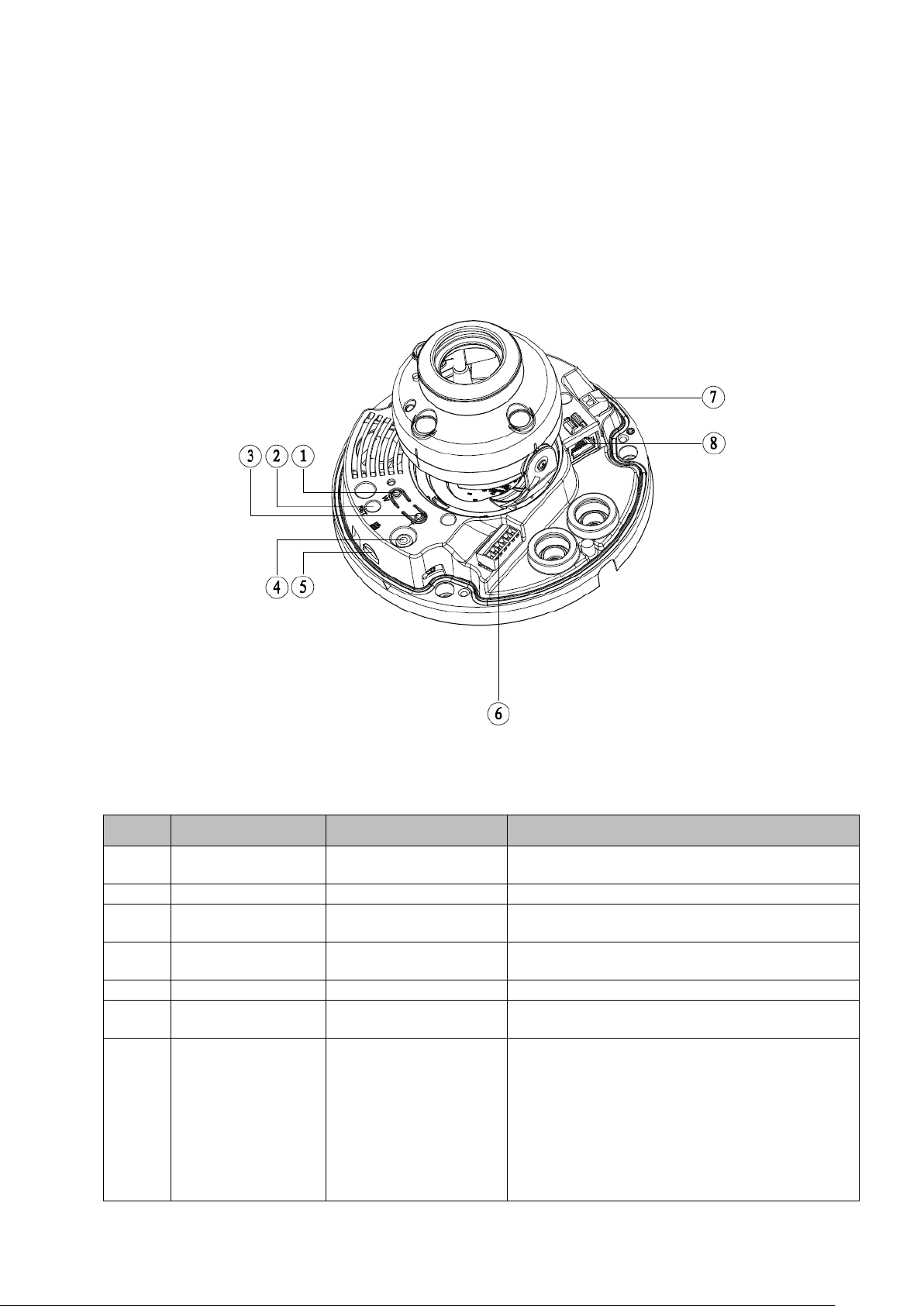
Adjust lens to wide angle end (image min
zoom)
2
RESET
Reset button
Reset button, restore devi c e fa ct or y default.
Adjust lens to telephoto end ( i ma ge max
zoom)
Output analog video signa l, able t o
connect to TV monitor to view i ma ge.
5
Micro SD
Micro SD slot
Connect Micro SD for local storage
Include alarm input, output and audio input,
output.
pin converter cable when you
se in accordance with device
1 Structure
Note:
The following figure is for reference only , which is used to know the functions of device external ports.
There are differences about external ports for so m e product models, please refer to the actual object
for more details.
1.1 Port Description
You can refer to the following fig ur e f or more details. See Figure 1-1.
Figure 1-1
Please refer to the following sheet for detailed information.
SN Port Port Name Function Description
1 Zoom W -
3 Zoom T 4 VIDEO_OUT -
6 I/O I/O port
Power port, input DC12V or AC 24V.
Note:
Please connect the default DC5.5 round
7 POWER Power input port
port to 2are using AC 24V power.
Actual u
label instruction.
Page 7

2
Connect to standard Ether net
Support POE function
8 LAN Network port
1.2 Framework and Dimension
Note: The following figures are for reference only, which ar e us ed to know the device dimensi on,
please refer to the actual produc t for more details.
Please refer to the following f igure for dimension informat io n. The unit is mm. See Figur e 1-2 and
Figure 1-3.
Figure 1-2 Dimension illustration
Page 8

3
Figure 1-3 Dimension illustration
1.3 Bidirectional Talk
Note: Some products do not suppor t bi dir ectional talk, which cannot be applied to this chapter.
1.3.1 Device-end to PC-end Device Connection
First, please connect the speaker or the MI C to t he audio input port of the device. Then c onnect the
earphone to the audio out put por t of the PC. Login the Web and then c l ick the “Talk” button to enable
the bidirectional talk funct i on. You can see the button beco m es or ange after you enabled t he
bidirectional talk functio n. Click Talk button again to st op t he bi directional talk function.
Listening Operation
At the device end, input the audio information to the speaker or M I C, and t hen you can get the audio
transmitted from device-end via the earphone or sound box at t he pc -end.
1.3.2 PC-end to the Device-end Device Connection
First connect the speaker or the MIC to the aud io in put por t of the PC. Then connect the ear phone to
the audio output port of the device. Login the Web and t hen click the “Talk” button to enable the
bidirectional talk functio n. You can see the button beco mes orange after you enabled the audio talk
function. Click Talk button again to stop the bidirecti onal talk function.
Please note the on-site listening operation is null duri ng the bidirectional talk process.
Listening Operation
Page 9

4
At the PC-end, input the audio information to t he speaker or MIC, and then you can get t he audio
transmitted from the PC-end via the earphone or sound box at the device-end.
1.4 Alarm Setup
Note:
It is only supported by some series product s.
Figure 1-4
Alarm input, output descr i pt ion:
Step 1 Connect alarm input device t o t he alarm input of I/O cable.
Step 2 Connect alarm output device to the alarm output of I/O cable, alarm out put is collector open
circuit output which connects 10K resistor to 3.3V externally.
Step 3 Open the Web, set alarm input and output correspondingly. Alarm input on WEB
corresponds to I/O cable on dev ice. When there is alarm, alarm input device will generate
signal of high and low level. Set cor r esponding NO and NC input s.
Step 4 Set the WEB alarm output. The alarm output is for the alar m output port of the device. It is the
alarm output port of the I/O cable.
Please refer to the following f igure for alarm input informat ion. See Figure 1-5.
Alarm input: When the input signal is idle or grounded, t he device can collect the different statuses of
the alarm input port. When the input signal is connect ed t o 3.3V or is idle, the device collects t he logic
“1”. When the input signal is gr ounded, the device collects t he logic “0”.
Page 10

5
Figure 1-5
Please refer to the following f igure for alarm output inform ation. See Figure 1-6 and F igure 1-7.
Figure 1-6
Figure 1-7
Mode A: Level application . Alarm output high and low level, alarm output is OC; it needs to increase
pull-up resistance externally to work normally. M ax external pull-up level is 5V, max port current is
5mA. After external pull-up resistance is increased, the default of output sig nal is high level (external
pull-up voltage), and it swit ches t o low level when there is alarm output (when the working current is
5mA, output voltage is less t han 0. 8V).
Mode B: Switch application. Alarm output is used to driv e ext er nal circuit, max current is 30 m A, max
voltage is 5V, it is advised t o add a r elay if it is beyond the value.
Page 11

6
2 Device Installation
2.1 Installation Steps
Figure 2-1
Important
Before the installation, please make sure the inst al l at i on surface can at least support 3x weight
of the camera and the br acket .
Please follow the steps lis t ed bel ow to install the device. Please ref er t o Fig ure 2-1 for reference.
Step 1
Use star-shaped wrench in the ac cessories bag to unscrew the three star-shaped screws on the dome
enclosure, and then open t he dome enclosure.
Step 2
Please take out the instal l ation position map in the access or ies bag, and then paste it on the c ei li ng or
the wall according to your monitor ar ea requirements.
Step 3
Find “cross” signs on the map, and dig three plastic expansion bolts hol es on the installation surf ace
and then insert three expansion bolts into the holes. Secure these three bolts firmly.
Step 4
Adjust the device installation pedestal to the proper position and then pull cable t hr ough the exit hole
on the installation surfac e. Line up the three screw holes in the device pedestal to the three plastic
expansion bolt holes in the installation position. Put the t hr ee installation screws into the three plastic
expansion bolts and secure them firmly . Fix the pedestal on the installatio n surface.
Page 12

7
Step 5
Adjust the lens to the needed an gl e according to the application r equirements of the location.
Hold the screw location of the rotation bracket on bot h sides, t ur n t he r ot at ion bracket horizont ally,
adjust the lens direction h or izontally to the targeted posit ion; unscrew the two locking screws on both
sides (do not remove them co m pl etely, just make them loose), hold the IR light decoration cov er t o
make the lens rotate verti cally, adjust the vertical di r ect ion of lens to a proper monitoring angle, then
tighten the locking screws on both sides ; H old the IR light decoration cover t o r otate horizontally,
adjust the image and adjust the lens horizontal direct ion t o t he t ar get ed location; Range of adj usting
lens angle: vertical (0°~+65°), horizontal (0°~+355°).
Figure 2-2
Step 6 Take up the dome enclosure; aim the location of s ide cable exit and cover the enclosure, use
inner hex wrench to secure t hr ee camera screws firmly. So far, t he installation is completed.
Side Wiring
When cable installation ad opt s s id e wiring, it needs to pull out the plast i c dec oration plug on the lateral
side of the device pedestal, and t hen the cable can be pulled out t hr ough the lateral side of the
pedestal.
Cable Connection
The device reserves two wiring holes, and supports the pin whose diameter is less than 15mm to pass.
The device is equipped wit h two waterproof sealing plugs . The w at er proof sealing plug can be us ed t o
block wiring hole and thre ading, which supports the cable whose diameter is between 4. 0mm ~ 6.0mm
to pass. It also makes it convenient for the users to operate waterproof work for leadin g wire by
themselves.
Please refer to the following st eps for the exact use:
Step 1
Take out the waterproof s ealing plug, and pull the cabl e w ith 4.0mm~6.0mm diameter t hr ough the
sealing plug according to the direction shown in the followin g f igure.
Page 13

8
Figure 2-3
Step 2
Before step 4 of device in st all at io n, install the cable with wat er pr oof sealing plug on the pedestal
through the installation hol e under t he device pedestal, and assemble the cable pin.
Step 3
Connect the pin accessed with cable to the device, and then install the device accord ing to the normal
steps.
2.2 Micro SD Card Installati on
Note:
Some series products do not support the Micro SD card storage functio n, w hich can’t be applied to the
following chapter.
Please shut down the power and t hen t ur n off the device before you install the Micro SD card.
Step 1
Open the device enclosur e ac cor ding to the step 1 in the dev ice i nst allation.
Step 2
Find the “Micro SD” sign in the device; adjust the direction of M icr o S D card according to the direct i on
shown on the device, inser t the card into the slot and install the Micro SD card well.
Figure 2-4
Page 14

9
3 Network Configuration
The IP address of all the cameras i s the same when leaving fac t or y (default IP192.168.1.108), in order
to make the camera get access t o the network smoothly, please plan the useable IP segment
reasonably according to t he act ual network environment.
3.1 Modify IP Address
IP address can be acquired and modified through quick configuration tool for the cameras which are
accessed via wired network, it needs to connect wired network to configure wireless parameters
before using wireless network cameras. In this chapter, it will introduce the approach of modifying IP
address via “Quick Configuration Tool”; also you can modify the IP address in the network parameters
of the WEB interface, please refer to the document in the disk << WEB Operation Manual>> for more
details.
Note:
Currently the quick configuration tool only supports the cameras which apply to the same network
segment with computer I P addr ess.
Step 1 Double click the “ConfigTools.exe” and open t he quick configuration tool.
Step 2 Double click the device to be configured, the system will pop out the “Login” dialog box. Enter
the IP address, user name, password and por t number of the camera, and c l i c k “Confirm”.
Note:
The default user name and password are admin and admin respectively, the default of port is
37777. See Figure 3-1 for more details.
Page 15

10
Figure 3-1
Step 3 Mo di fy the camera IP address on the “Net” interface, click “Save” to finish modification.
See Figure 3-2 for more details.
Figure 3-2
3.2 Login WEB Interface
Note:
Different devices may have different WEB interfaces, the figures below are just for reference, please
refer to the document <<WEB Operation Manual>> in the disk and the actual interf ace for more details
Step 1 Ope n I E and input the modified camera I P address in the address bar.
Step 2 The login interface is shown below, please input your user name and password (Default user
name is admin and password is admin respectively), click “login”.
See Figure 3-3 for more details.
Page 16

11
Figure 3-3
Step 3 Install controls according to the system prompt; see Figure 3-4 for the WEB main interface.
Please modify the administrator password as s oon as possible after y ou successfully logged in.
Figure 3-4
Page 17

12
Note
This user’s manual is for ref er ence only. Slight difference may be found in user interface.
All the designs and software here are subject to change without prior writ ten noti ce.
All trademarks and registered trademarks mentioned are the prope rties of their respective
owners.
If there is any uncertainty or controversy, please refer to the final explanat i on of us.
Please visit our website for more information.
 Loading...