

Page 1

INSTRUCTION MANUAL
Page 2

Page 3

Features and Specifications
a. Overview 1
b. Features 2
c. IC720 App 2
d. Specifications 3-4
e. Dimensions 5
Camera Installation
a. Ceiling Installation 6-8
b. Corner/Pole Mount 9-11
Web GUI | IC720 Management
a. Network Connection 12
b. Logging In, and Main Inter face 13-14
c. Connecting IC720 to an NVR 15-16
Appendices
a. Toxic or Hazardous Elements 17
TABLE OF CONTENTS
Page 4

IC REALTIME
1 | FEATURES AND SPECIFICATIONS
Page 5

This section outlines the primary features of the IC Realtime IC720
Cam er a. It al so outlin es b asic Ar ch it ec tu ral a nd En gi ne ering
specifications.
1a. O VER VIE W
This IC Re al ti me se ri es pr od uc t is an excel le nt si tu at io na l a wa reness
IP Camera – the camera designed to see everything with no blind
spots. It adop ts a dual lens d esign, and is p ow ered by a r ob us t
Qualcomm, Snapdragon 800 series processor, enabling it to maintain
reliable, 24/7 operation. Utilizing both H.264 video compression
and AAC audio compression technology enables the highest quality
of recor de d a ud io/v id eo , w hi le ma inta ining the lowest bi tr ate
utilization.
The IC720 series camera is an HD, dual lens 12 MegaPixel IP Camera
with an integrated microphone. The dual lens design of the camera
allows for video capture in a full 360 degree vertical and 360 degree
horizontal format. This camera is fully suited for full operation as a
standalone device.
The 12MP recording resolution and extreme wide angle lens design
makes this IPC well equipped for installation in various institutions
ranging f rom res id en tial, c om mercial , governmen tal, a nd ente rprise
environments.
1
Page 6

IC REALTIME
1b. FEATURES
IC Realtime IC720 series IP Cameras all support the following features:
HD, 360 x 360 Video Monitoring: This IP Camera uses two SONY
IMX172 (12MP) sensors.
Secure Archiving: Audio Video data is compressed and packaged
into a secure, and watermarked video format. This bolsters archived
vi deo in tegrit y, and prevents vi ci ou s da ta man ip ulation. Vi de o is
also watermarked with special data for evidentiary purposes.
Compression Format: H.264 video and AAC audio enables high
quali t y vi de o recordi ng w hi le m aint aining th e lo we st f ile si zes
possible.
SD Card Storage: As a standalone device, the IPC can hold a 32GB
micro SD card suitable for storing video direc t from the camera.
1c. I C720 A PP
Network Operation: Full system control (including live view,
playback , backup,V PTZ cont ro l, and sys te m conf ig uration) is av ai lable
with over the network. Client software is available for both Mac and
PC systems.
VPTZ Control: This IPC includes a special dewarping algorithm,
enabling users to ‘Vir tually’ Pan/Tilt /Zoom across a high resolution
image , in or de r to get the h ighest visibil it y and situational awarene ss
from the camera.
2
Page 7
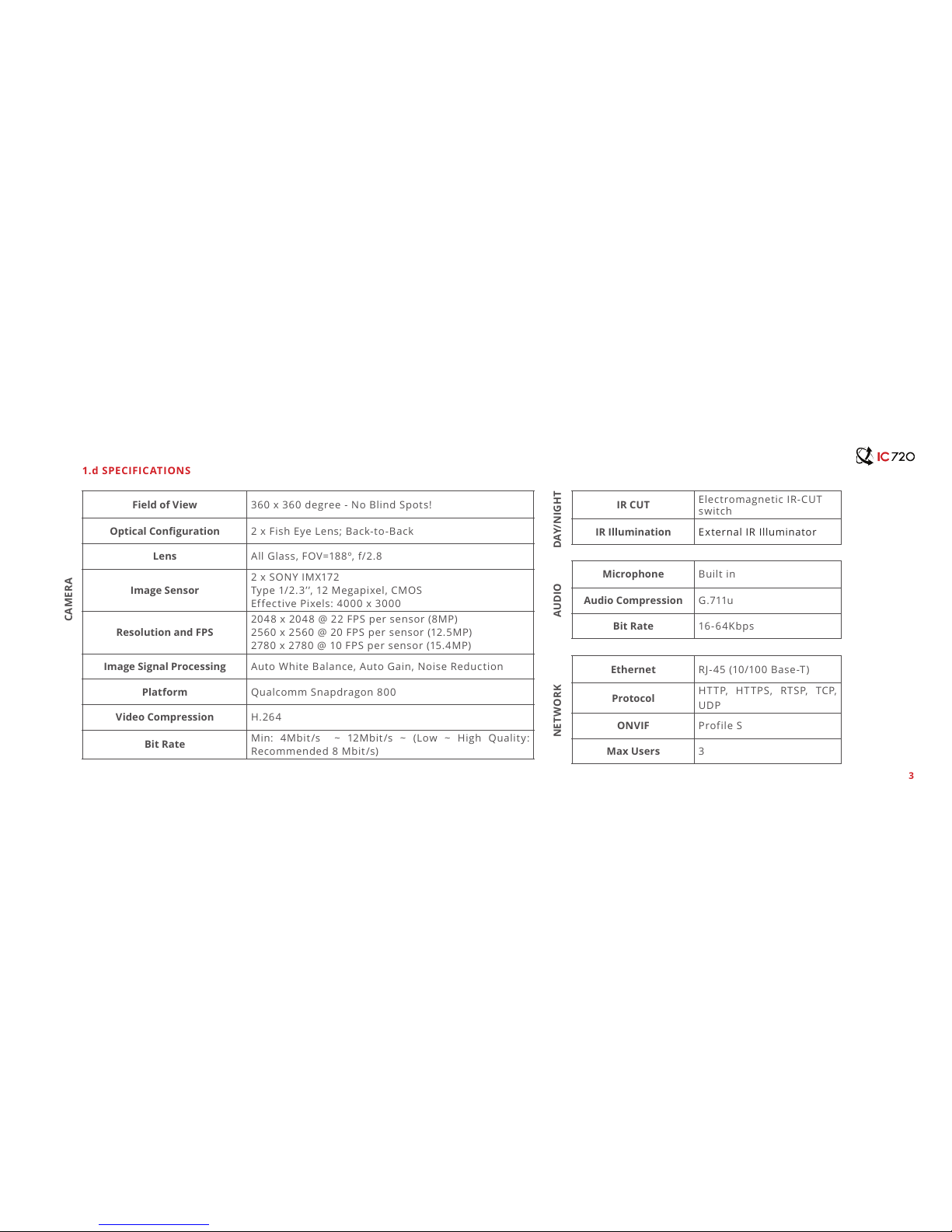
Field of View 360 x 360 degree - No Blind Spots!
Optical Conguration 2 x Fish Eye Lens; Back-to-Back
Lens All Glass, FOV=188º, f/2.8
Image Sensor
2 x SONY IMX172
Typ e 1/2.3 ’ ’, 12 M egapixe l, CM OS
Effective Pixels: 4000 x 3000
Resolution and FPS
2048 x 2048 @ 22 FPS per sensor (8MP)
2560 x 2560 @ 20 FPS per sensor (12.5MP)
2780 x 2780 @ 10 FPS per sensor (15.4MP)
Image Signal Processing Auto White Balance, Auto Gain, Noise Reduction
Platform Qualcomm Snapdragon 800
Video Compression H.264
Bit Rate
Min: 4Mbit/s ~ 12Mbit/s ~ (Low ~ High Quality:
Recommended 8 Mbit/s)
IR CUT
Electromagnetic IR-CUT
switch
IR Illumination External IR Illuminator
Microphone Built in
Audio Compression G.711u
Bit Rate 16- 64K bp s
Ethernet RJ-45 (10/100 Base-T)
Protocol
HTTP, HTTPS, RTSP, TCP,
UDP
ONVIF Profile S
Max Users 3
1.d SPECIFIC ATIONS
CAMERA
DAY/NIGHTAUDIONETWORK
3
Page 8

IC REALTIME
NVR IC Realtime NVR-8128; NVR-8256
Memory Slot Micro SD (up to 32GB
Power Supply 12VD C, PoE
Power Consumption ~8 Watts
Mount Wall, Ceiling, Corner, Pole
Size 4.2’’ x 11.7’’ x 2.9’’ (108mm x 293mm x 73mm)
Weight ~3 lbs
Protection For Indoor use only
Working environment 40-95 degrees F / 10-35 degrees C; 10%-80%
STORAGEPOWEROTHER
4
1.d SPECIFIC ATIONS (Continued)
Page 9

The ‘front’ of the IC720 Camera. Ceiling mount orientation.
1.e DIMENSIONAL VIEWS
Bottom view of the IC720 Camera. The cable harness extends out of the center.
5
Page 10

IC REALTIME
2 | CAMERA INSTALLATION
Page 11

The IC720 in a Ceiling mount configuration.
2.a CEILING INSTALLATION: S TEP BY STEP
This section outlines the proper way to mount and install an
IC720 series IP Camera. Suitable methods of installing the
IPC i nc lude ei th er Ce il in g ins tallat ion, Co rner in st al la ti on, or
Pole Installation. Note that hardware including screws and
anchors are included for the camera installation.
6
Page 12

IC REALTIME
The Beauty shroud simply slides over the camera body to provide a
sleek installation t and feel.
The Beauty shroud simply slides over the camera body to provide a
sleek installation t and feel.
Step 1: Install the Beauty Shroud
Slide the shroud over the IC720 Camera body from the top.
Step 2: Install the Interface Plate
At tach the in terf ac e plate wi th (4) # 10-24 Pan H ea d scre ws
and lo ck ing washers. Tigh te n to s ec ur e th e inte rface plat e
to the camera body.
7
Page 13

The full camera assembly, prior to permanent installation. (3) M3
Cap Screws x the camera assembly to the ceiling mount.
Ethernet cable being plug ged into modem, routher, or switch board.
Step 3: Connect Wiring
Pass cables the cables through the pole mount and then connect
your Ethernet and power cables (if not using Power Over
Ethernet) . Once p hy sica l ca bl e connec ti on s ar e es tabl is he d, t he
camera can be permanently affixed to the interface plate.
Step 4: Secure the Camera Assembly to the Ceiling Mount
Secure the assembly to the ceiling mount itself with (3) M3
Cap screws.
8
Page 14

IC REALTIME
The IC720 Beam in a Pole Mount installation.
2.b CORNER/POLE MOUNT: STEP BY STEP
This section outlines the proper way to mount and install an IC720
ser ie s IP C amera. S uitable m et ho ds of i ns ta lling t he IPC in cl ude e it he r
Ceiling installation , Corner installation, or Pole Installation. Note that
hardwar e inclu di ng sc re ws a nd anch or s are i nc luded f or the ca mera
installation.
9
Page 15

The Beauty shroud simply slides over the camera body to provide a
sleek installation t and feel.
Attaching the interface plate to the camera body.
Note: Install the beauty shroud prior to this step!
Step 1: Install the Beauty Shroud
Slide the shroud over the IC720 Camera body from the top.
Step 2: Install the Interface Plate
At tach the in terf ac e plate wi th (4) # 10-24 Pan H ea d scre ws
and lo ck ing washers. Tigh te n to s ec ur e th e inte rface plat e
to the camera body.
10
Page 16

IC REALTIME
The full camera assembly, prior to permanent installation. (4) M8
Cap Screws x the camera assembly to the pole mount.
Step 4: Secure the Camera Assembly to the Pole Mount
Secure the assembly to the ceiling mount itself with (4) M8
Pan Head screws.
Step 3: Connect Wiring
Connect your Ethernet and power cables (if not using Power Over
Ethernet) . Once p hy sica l c able co nn ec tion s are e st abli shed, t he
camera can be permanently affixed to the interface plate.
11
Ethernet cable being plug ged into modem, routher, or switch board.
Page 17

3 | WEB GUI | IC720 MANAGEMENT
Page 18

IC REALTIME
This section outlines how to assign an IP address to the camera, and
how to access and configure the IC720 Beam via it’s built in Web
Interface. The Web Interface is used primarily to configure the camera
parameters initially. The IC720 application is the desired client
software to use with when viewing the IC720 Beam series camera.
3a. NETWORK CONNECTION
IC Realtime IC720 Beam series IP Cameras all support the following
features:
Step 1: Ensure the Camera is physically connected to your
Network, and Powered ON.
Pat ch the IP Camera i nto yo ur net work wi th a sta ndard Et hernet
cable. Pro vide the cam er a wi th pow er eit he r vi a PoE or wit h th e
separate 12VDC power input jack.
Step 2: Assign an IP address to the IP Camera.
The IC720 Beam Series camera (and all ICR IP Cameras) are designed
to automatically assign an IP address from the router on your local
area network (via DHCP).
You can use ou r IP A ut o Se ar ch u tility to rapidly fi nd a nd c hange IP
addresses for IC720 Beam series IP Cameras. The utility is available
on our support page at :
http://www.icrealtime.com/support /software-downloads
12
Page 19

3.b LOGGING IN, AND MAIN INTERFACE
Step 1: Open up your Web Browser (Safari, Chrome, Firefox, or
IE) and input the IP address of your IP camera.
In Example, open Safari and browse to http://192.168.1.108
Step 2: Login to the camera with the default credentials
By default, the username is ‘admin’ and the password is ‘admin’. It is
always strongly recommended to change the default passwords after
the initial setup. The cameras login page should appea as shown.
13
Page 20

IC REALTIME
Step 3: Change setup parameters as needed
Once logged into the Web Interface, you will be presented with 5
options from the Menu Tree on the left side:
Camera Menu allows you to change Resolution, FrameRate, and
BitRate parameters.
Network Menu allo ws you to assig n an IP addre ss , as we ll as c ha nge
the default port settings.
System Menu allows for configuration of the Date/Time, Language,
as well as the IC720 Beam camera device logs.
Accounts Menu allows you to manage accounts (Add/Delete/
Modify), change passwords, and create different Roles.
Information Menu provides Version information, as well as
Firmware Updates for the IC720 Beam series camera.
14
Page 21

3.c Connecting IC720 to an NVR
IC720 utilizes the industr y standard ONVIF protocol, so connecting
to an NVR should be a breeze. Each image of the camera (2 total)
has an independent ONVIF port number for connection. Here’s an
example of pairing the IC720 device to an ICRealtime NVR.
Step 1: Login to the ICRealtime NVR series device, and navigate
to the ‘Remote Devices’ menu.
Step 2: Hit ‘Device Search’ on this page to scan your LAN for any
IC720 series cameras.
15
Page 22

IC REALTIME
Step 3: Double click on the IP Address of your IC720 from the
‘Device Search’ menu to add the first IC720 sensor.
This wil l au tomaticall y ad d this to you r NVR , w it ho ut nee ding to in pu t
any additional information.
Step 4: Double click on the same IP Address again, if you want to
add the second sensor (you will need to change the port number
in the table below).
Ag ai n, this wil l autom at ic al ly add the First sens or conn ec tion info
to your NVR. Simply select this newly added Remote Device, click
Modify, and change the Port Number from 8070 to 8071, and Save.
This will pair the NVR to the second sensor!
16
Page 23

4 | APPENDIX: TOXIC AND HAZARDOUS
MATERIALS REPORT
Page 24

IC REALTIME
Note
This user manual is intended for reference only. Slight
diff er en ces may be fou nd in th e u se r inter fa ce as
products continually develop.
Al l de si gn s an d sof t ware her ein ar e su bj ec t to ch ange
without prior written consent.
All trademarks and registered trademarks mentioned
are the properties of their respective owners.
Please visit http://www.icrealtime.com for more
information.
Component Name
Tox ic or Haz ar dou s Ma ter ia ls o r Ele ments
Pb Hg Cd Cr VI PBB PBDE
Circuit Board Component
Device Case
Wire and Cable
Packaging Components
Video Compression
Bit Rate
17
Page 25

Page 26

© 2015 IC Realtime, LLC.
3050 N Andrews Ave Ext
Pompano Beach, FL 33064
Phone 866.997.9009 • Fax 866.860.3860
 Loading...