

Page 1
INSTALLATION AND QUICK SETUP GUIDE
WWW.ICREALTIME.COM
www.ICRealtime.com EL-ID1
- 1 -
Page 2

Index – EL-ID1 Camera
Description___________________________________________________3
Parts List_____________________________________________________4
Guidelines____________________________________________________5
Specifications of EL-ID1________________________________________6
Mounting the EL-ID1___________________________________________7
Camera Adjustment__________________________________________8, 9
- 2 -
Page 3

Description
IC Realtime is pleased to introduce the EL-ID1, the most advanced license
plate camera available. Installed at access points, the EL-ID1 captures plates
of vehicles entering and exiting properties at speeds of up to 30mph, from a
15-25ft range. Built-in infrared illumination enables plate capture under any
lighting condition; while intelligent saturation technology eliminates motion
blur and headlight/sunlight glare for a high-contrast image.
Delivering perfect plate capture, the EL-ID1 allows the identification of
front and rear license plates regardless of the weather or lighting conditions.
The EL-ID1 is also a far more cost efficient solution than other plate
cameras without sacrificing quality.
Main Features
• Clear Image of License Plate Under Most Weather Or Light
Conditions
• Highly enhanced resolution of 600 TVL
• 1/3" IDX B/W CCD
• 16mm Fixed Omni-focus lens with multi-focusing technology
• Dual switching power (w/Auto Line-lock) 24VDC / 24VAC
• IP67 Weatherproof
- 3 -
Page 4

Parts List
The items included in the packing box are as follows:
• EL-ID1 Camera
• Sunshield
• 24VDC 1.9Amp Power Transformer
• Instruction Booklet
• Power/Video Pigtail
- 4 -
Page 5

Guidelines
These following installation guidelines must be followed for proper and
consistent license plate capturing:
• The EL-ID1 must be installed and mounted in an area which is free
from falling objects.
• The mounting surface must be secure to handle the weight of the
camera and free from vibration.
• When the camera is mounted and initial setup is ready it would ensure
consistency to park a vehicle at the capture point for testing purposes.
CAUTION
Install the EL-ID1 in an appropriate location which does not exceed any
environmental conditions as noted on the specifications (pg.6).
- 5 -
Page 6

Specifications
Image Sensor 1/3" IDX B/W CCD
H.Resolution 600 TVL
Effective Pixels 768(H)X494(V)
Scanning System 2:1 Interlaced
Synchronization
Internal
System
S/N Ratio Greater than 50dB (AGC Off)
Video output 1.0Vp-p Composite. 75 Ohms
Min. Illumination 0 Lux at F2.0 (IR On)
Shutter Speed 1/1000 sec
Gamma correction Standard r=0.45
Smear Effect 0.005%
Power source 24VDC / 24VAC
Operating current At 24VDC 1AMP
Lens 16mm fixed omni-focus lens(multi-focusing)
Viewable Distance > 16ft in zero light
IR Spectrum 850nm
Operating
Temperature
14˚F~122˚F (-10˚C~+50˚C) // -40˚F~122˚F (-
40˚C~+50˚C) - with heater option
Measurement (mm) 121.5(D) X 164(L)
Weight (Approx.g) 900
Humidity Within 90% RH
- 6 -
Page 7

Mounting the EL-ID1
Mounting the EL-ID1 in an ideal location will ensure consistency of license
plate capturing during all weather and lighting conditions. The EL-ID1
camera has a 16mm omni-focus lens. This will output a video signal with a
horizontal FOV (Field of View) of 17.06° and a vertical FOV of 12.84°. The
EL-ID1 is effective from a 15-25ft range. Though, optimal distance from the
camera to the capture point is 18ft. This will result in a capture width of 5.4ft
and a height of 4.1ft. For greater consistency also make sure the camera does
not exceed a horizontal or vertical angle greater than 40° from the car’s
license plate. Mounting the camera at a greater angle will result in
inconsistency and fewer legible characters on the license plate. Even though
40° is the maximum mountable angle the ideal location would be closest to
0° from the car on both horizontal and vertical angles. See the diagram
below for mountable angles.
- 7 -
Page 8
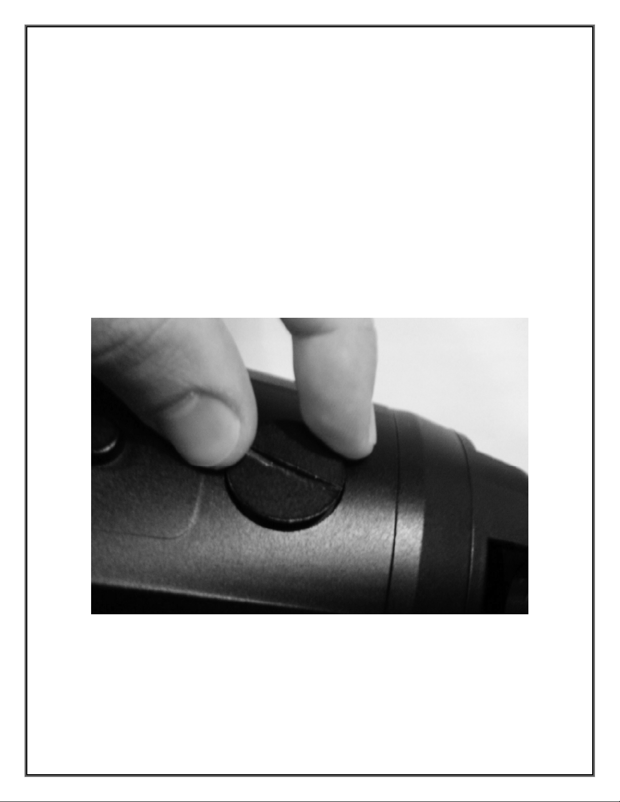
Camera Adjustments
The IR potentiometer is the only camera adjustment on the EL-ID1. This
allows the user to adjust the intensity of the IR’s for different capture points.
To access this mechanism please follow these steps:
• Access the IR potentiometer by removing the round entry plate
located on the top of the EL-ID1. Turn Counterclockwise for removal
(see below).
- 8 -
Page 9
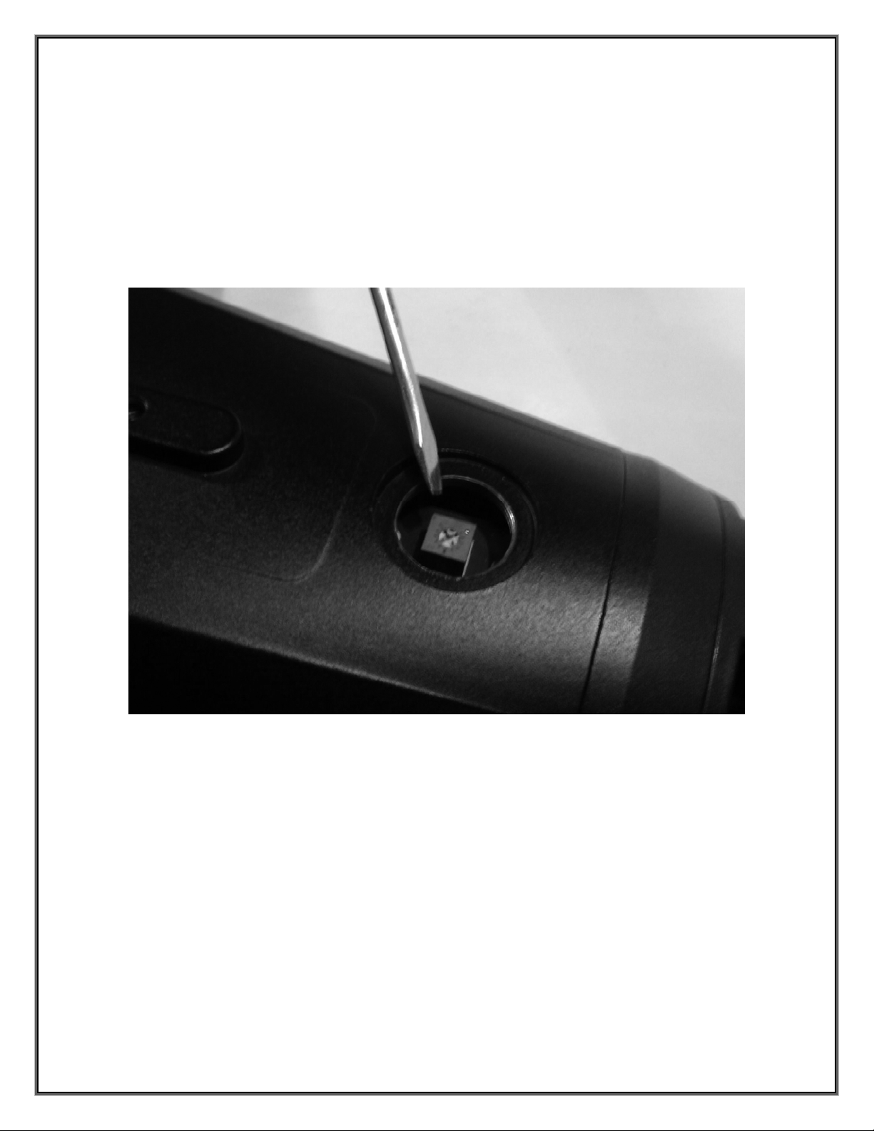
• When the plate has been removed, utilize a small Phillips Head screw
driver to adjust the IR potentiometer (see below). Counter clockwise
will increase the IR intensity. Clockwise will decrease the intensity of
the IR’s.
- 9 -
Page 10

www.ICRealtime.com
Corporate Headquarters:
3050 N. Andrews Ave. Ext.
Pompano Beach, FL 33064
PH: (954)-772-5327
FX: (954)-827-5900
West Coast Office:
14200 West Van Buren St.
Suite C-106
Goodyear, AZ 85338
PH: (602)-910-3432
FX: (602)-626-3545
European Office:
34 Eastgate Drive
Little Island, Cork
Ireland
PH: 021 435-5818
FX: 021 435-5817
- 10 -
 Loading...