

Page 1

Mobile Digital Video Recorder User’s Manual
V 2.0.0
Page 2

i
Table of Contents
1 Features and Specifications ...............................................................................................................1
1.1 Overview ........................................................................................................................................1
1.2 Function .........................................................................................................................................1
1.3 Features .........................................................................................................................................2
1.4 Specifications ................................................................................................................................3
2 Front Panel and Rear Panel ...............................................................................................................8
2.1 Front Panel ....................................................................................................................................8
2.2 Rear Panel ....................................................................................................................................9
2.2.1 Rea Panel ...............................................................................................................................9
2.2.2 Extension Port ......................................................................................................................10
2.2.3 Bidirectional talk port ........................................................................................................... 11
2.2.4 VGA ....................................................................................................................................... 11
2.3 Remote Control...........................................................................................................................12
2.4 Mouse Operation ........................................................................................................................14
3 Installation and Connections ............................................................................................................16
3.1 Check Unpacked DVR...............................................................................................................16
3.2 About Front Panel and Rear Panel..........................................................................................16
3.3 HDD/SIM Card Installation ........................................................................................................16
3.3.1 HDD Installation ...................................................................................................................16
3.3.2 SIM Card Installation ...........................................................................................................18
3.4 Connecting Power Supply .........................................................................................................18
3.5 Connecting Audio/Video Input and Output Devices ..............................................................18
3.5.1 Connecting Video Input ......................................................................................................18
3.5.2 Audio Input ...........................................................................................................................19
3.5.3 Audio/Video Input Switch Cable ........................................................................................19
3.6 Connecting Audio/Video Output and Output Devices ...........................................................20
3.6.1 Connecting Video Output ...................................................................................................20
3.6.2 Audio Output ........................................................................................................................20
3.6.3 Audio/Video Output Switch Cable .....................................................................................20
3.7 Alarm Input and Output Connection ........................................................................................21
3.7.1 Alarm Input and Output Details .........................................................................................21
3.7.2 Alarm Input Port ...................................................................................................................22
3.7.3 Alarm Output Port ................................................................................................................22
4 Operation .............................................................................................................................................24
4.1 Boot up& Shutdown ...................................................................................................................24
4.1.1 Boot up ..................................................................................................................................24
4.1.2 Schedule Boot up & Shutdown ..........................................................................................24
4.2 Startup Wizard ............................................................................................................................24
4.3 Login .............................................................................................................................................25
4.4 Preview ........................................................................................................................................25
4.5 Right-Click Menu ........................................................................................................................26
4.5.1 Window Switch.....................................................................................................................26
4.5.2 PTZ Control ..........................................................................................................................27
Page 3

ii
4.5.3 Color ......................................................................................................................................27
4.5.4 Search ...................................................................................................................................27
4.5.5 Record Control .....................................................................................................................28
4.5.6 Alarm Output ........................................................................................................................28
4.5.7 Zero-channel encoding .......................................................................................................28
4.5.8 Main Menu ............................................................................................................................28
4.6 Search & Playback .....................................................................................................................28
4.7 Information ..................................................................................................................................31
4.7.1 HDD Information ..................................................................................................................32
4.7.2 BPS........................................................................................................................................33
4.7.3 Log .........................................................................................................................................34
4.7.4 Version ..................................................................................................................................35
4.7.5 Device ...................................................................................................................................36
4.7.6 Online Users.........................................................................................................................36
4.7.7 Network Test ........................................................................................................................36
4.7.8 Network Load .......................................................................................................................37
4.8 Vehicle .........................................................................................................................................37
4.8.1 3G ..........................................................................................................................................38
4.8.2 WIFI .......................................................................................................................................39
4.8.3 G-Sensor...............................................................................................................................42
4.8.4 Register .................................................................................................................................42
4.8.5 Auto Maintenance ...............................................................................................................43
4.8.6 Abnormal...............................................................................................................................44
4.8.7 TV Adjust...............................................................................................................................45
4.9 Setting ..........................................................................................................................................46
4.9.1 General .................................................................................................................................46
4.9.2 Encode ..................................................................................................................................48
4.9.3 Schedule ...............................................................................................................................51
4.9.4 RS232 ...................................................................................................................................52
4.9.5 Network .................................................................................................................................53
4.9.5.1 Network Setting ..........................................................................................................54
4.9.5.2 NTP Setup ...................................................................................................................54
4.9.5.3 DDNS ...........................................................................................................................55
4.9.5.4 Email.............................................................................................................................57
4.9.5.5 FTP ...............................................................................................................................58
4.9.5.6 Alarm center ................................................................................................................59
4.9.6 Alarm .....................................................................................................................................60
4.9.7 Detect ....................................................................................................................................62
4.9.7.1 Video Loss ...................................................................................................................62
4.9.7.2 Tampering ....................................................................................................................63
4.9.8 PTZ ........................................................................................................................................64
4.9.9 Display...................................................................................................................................66
4.9.10 Default ...................................................................................................................................67
4.10 Advanced .....................................................................................................................................68
4.10.1 HDD Management ...............................................................................................................69
4.10.2 Alarm Output ........................................................................................................................70
Page 4

iii
4.10.3 Manual Record.....................................................................................................................70
4.10.3.1 Manual record menu ..................................................................................................70
4.10.3.2 Basic operation ...........................................................................................................70
4.10.3.3 Enable/disable record ................................................................................................71
4.10.3.4 Enable all channel recording ....................................................................................71
4.10.3.5 Stop all channel recording .........................................................................................72
4.10.4 Account .................................................................................................................................73
4.10.4.1 Modify Password ........................................................................................................73
4.10.4.2 Add/Modify Group ......................................................................................................74
4.10.4.3 Add/Modify User .........................................................................................................74
4.10.5 Import/Export ........................................................................................................................75
4.11 Backup .........................................................................................................................................75
4.11.1 Detect Device .......................................................................................................................75
4.11.2 Backup ..................................................................................................................................76
4.12 Shutdown .....................................................................................................................................77
5 WEB OPERATION .............................................................................................................................78
5.1 Network Connection...................................................................................................................78
5.2 Login .............................................................................................................................................78
5.3 LAN Mode....................................................................................................................................80
5.4 Real-time Monitor .......................................................................................................................81
5.5 PTZ ...............................................................................................................................................82
5.6 Image/Relay-out .........................................................................................................................83
5.6.1 Image ....................................................................................................................................83
5.6.2 Relay output .........................................................................................................................84
5.7 Zero-channel encoding ..............................................................................................................84
5.8 WAN Login ..................................................................................................................................84
5.9 Setup ............................................................................................................................................85
5.9.1 Channel .................................................................................................................................85
5.9.1.1 Conditions ....................................................................................................................85
5.9.1.2 Video and Audio..........................................................................................................87
5.9.1.2.1 Encode.........................................................................................................................87
5.9.1.2.2 Snapshot ......................................................................................................................88
5.9.1.2.3 Overlay ........................................................................................................................89
5.9.1.2.4 Zero-Ch Encoding .......................................................................................................90
5.9.1.2.5 Preview Overlay ..........................................................................................................90
5.9.1.2.6 Path .............................................................................................................................91
5.9.1.3 Channel Name ............................................................................................................91
5.9.2 Network .................................................................................................................................91
5.9.2.1 TCP/IP ..........................................................................................................................91
5.9.2.2 Connection ..................................................................................................................93
5.9.2.3 DDNS ...........................................................................................................................93
5.9.2.4 Email.............................................................................................................................95
5.9.2.5 Alarm Centre ...............................................................................................................96
5.9.3 Event .....................................................................................................................................97
5.9.3.1 Video detect ................................................................................................................97
5.9.3.1.1 Video loss ....................................................................................................................97
Page 5

iv
5.9.3.1.2 Tampering ...................................................................................................................98
5.9.3.2 Alarm ............................................................................................................................99
5.9.3.2.1 Local Alarm ................................................................................................................99
5.9.3.2.2 Net Alarm ..................................................................................................................101
5.9.3.2.3 Alarm Out .................................................................................................................101
5.9.4 Storage ................................................................................................................................102
5.9.4.1 Schedule ....................................................................................................................102
5.9.4.2 Storage .......................................................................................................................103
5.9.4.2.1 Local Storage ............................................................................................................103
5.9.4.2.2 FTP ............................................................................................................................104
5.9.4.3 Record control ...........................................................................................................104
5.9.5 System ................................................................................................................................105
5.9.5.1 General ......................................................................................................................105
5.9.5.1.1 General ......................................................................................................................105
5.9.5.1.2 Date and time ............................................................................................................106
5.9.5.2 Account ......................................................................................................................107
5.9.5.2.1 User name .................................................................................................................108
5.9.5.2.2 Group ........................................................................................................................109
5.9.5.3 Default ........................................................................................................................ 110
5.9.5.4 Import/Export............................................................................................................. 111
5.9.5.5 Upgrade ..................................................................................................................... 111
5.9.5.6 RS232 ........................................................................................................................ 111
5.9.5.7 PTZ ............................................................................................................................. 112
5.9.6 Information .......................................................................................................................... 113
5.9.6.1 Version ....................................................................................................................... 113
5.9.6.2 Log .............................................................................................................................. 113
5.9.7 Vehicle ................................................................................................................................. 114
5.9.7.1 Vehicle ........................................................................................................................ 114
5.9.7.2 WIFI ............................................................................................................................ 115
5.9.7.3 3G ............................................................................................................................... 115
5.9.7.3.1 CDMA/GPRS ........................................................................................................... 116
5.9.7.3.2 Mobile ....................................................................................................................... 116
5.9.7.4 Auto Register ............................................................................................................ 117
5.9.7.5 Auto Maintenance .................................................................................................... 117
5.9.7.6 Abnormality ............................................................................................................... 118
5.9.7.7 Display .......................................................................................................................120
5.9.7.7.1 GUI ...........................................................................................................................120
5.9.7.7.2 TV Adjust ..................................................................................................................121
5.9.7.8 Sensor ........................................................................................................................121
5.9.7.8.1 Speed .........................................................................................................................121
5.9.7.8.2 G-Sensor ...................................................................................................................122
5.10 Playback ....................................................................................................................................122
5.10.1 Playback Record ...............................................................................................................124
5.10.2 Clip and Save Record .......................................................................................................124
5.10.3 File List ................................................................................................................................124
5.11 Alarm ..........................................................................................................................................127
Page 6

v
5.12 Log out .......................................................................................................................................127
5.13 Un-install Web Control .............................................................................................................128
6 Digital Surveillance System ............................................................................................................129
7 FAQ ....................................................................................................................................................130
8 Appendix A HDD Capacity Calculation .........................................................................................135
9 Appendix B Toxic or Hazardous Materials or Elements .............................................................136
Page 7

vi
Welcome
Thank you for purchasing our mobile digital video recorder!
This user’s manual is designed to be a reference tool for your system.
Please open the accessory bag to check the items one by one in accordance with the list below.
Contact your local retailer ASAP if something is missing or damaged in the bag.
Page 8

vii
Important Safeguards and Warnings
1.Electrical safety
All installation and operation here should conform to your local electrical safety codes.
We assume no liability or responsibility for all the fires or electrical shock caused by improper
handling or installation.
2.Transportation security
Heavy stress, violent vibration or water splash are not allowed during transportation, storage and
installation.
3.Installation
Keep upwards. Handle with care.
Do not apply power to the DVR before completing installation.
Do not place objects on the DVR
4.Qualified engineers needed
All the examination and repair work should be done by the qualified service engineers.
We are not liable for any problems caused by unauthorized modifications or attempted repair.
5.Environment
The DVR should be installed in a cool, dry place away from direct sunlight, inflammable, explosive
substances and etc.
This series product shall be transported, storage and used in the specified environments.
6. Accessories
Be sure to use all the accessories recommended by manufacturer.
Before installation, please open the package and check all the components are included.
Contact your local retailer ASAP if something is broken in your package.
Before your operation please read the following instructions carefully.
Installation environment
Keep away from extreme hot places and sources;
Avoid direct sunlight;
Keep away from extreme humid places;
Avoid violent vibration;
Do not put other devices on the top of the DVR;
Be installed in well ventilated place; do not block the vent.
Accessories
Always use accessories recommend by the manufacturer.
Page 9

1
1 Features and Specifications
1.1 Overview
This series mobile DVR is a series mobile DVR based on our latest platform.
It integrates video process, wireless network technology, GPS technology, structure
technology, and vehicle information sampling and process technology together.
It adopts solid aluminium alloy case and has built-in 2.5-inch HDD as the storage media.
Support built-in 3G/WIFI wireless transmission module and GPS module.
It can be used on the vehicle to realize local audio/video storage and vehicle information
sampling. It can send out real-time video and vehicle information to the remote
management centre via the WAN to build up a wireless surveillance management
system.
This series product can be widely used in various areas such as public transportation,
long-distance bus, public security patrol, public security, logistics transportation and etc. It can
also be sued in many environments which has high requirement for the video monitor.
Important
Please note, GPS, WIFI, 3G function are optional. Please make sure you purchased product
support these functions.
1.2 Function
Slight difference may be found due to different series products.
Storage function
Special data format to guarantee data security and can avoid vicious data modification.
Compression format
Support multiple-channel audio and video signal. An independent hardware decodes the audio
and video signal from each channel to maintain video and audio synchronization.
Backup function
Support backup operation via USB port (such as flash disk, portable HDD)
Client-end user can download the DVR file to local HDD to backup via network.
Record playback function
Support each channel real-time record independently, and at the same time it can support forward
play, network monitor, record search, download and etc.
Support various playback modes: slow play, fast play, backward play and frame by frame play.
Support time title overlay so that you can view event accurate occurred time
Support specified zone enlargement.
Network operation
Support network remote real-time monitor, remote record search and remote PTZ control.
Alarm activation function
Page 10

2
Several-channel relay on-off signal alarm output, easily to realize alarm trigger action and on-site
light control.
The alarm input port and output port has the protection circuit to guarantee device safety.
Communication port
RS485 port to realize alarm input and PTZ control.
RS232 port to connect to peripheral devices such as keyboard, COM port, matrix control and etc.
Standard 100Mbps Ethernet port can realize network access function.
PTZ control
Support PTZ decoder via the RS485 communication.
Support various decode protocols to realize PTZ and PTZ dome camera control function.
Intelligent operation
Mouse operation function
In the menu, support copy and paste setup function
GPS positioning
The GSP information can activate the record function while the search function can activate the
vehicle movement track.
Please note only the unit of GPS module supports this function.
3G network
Latest wireless network communication technology allows you to easily control the device.
Please note only the unit of 3G module supports this function.
Removable HDD design
The professional removable anti-vibration design supports fix and removable operation and can
connect to PC USB port to realize fast and convenience data backup.
Dual–stream
Considering the wireless network band is small and the network is not stable, system adopts the
dual stream to implement real-time record and network transmission independently, which greatly
optimizes the network transmission encode code and enhance the wireless network control
compatibility.
Vehicle status record
There are seven external alarm output ports. You can connect to the door signal, direction
indicator lamp signal, reversing light signal, stop lamp signal and etc to prompt the driver and
record vehicle status.
1.3 Features
Mobile vehicle power
Professional wide power supplying design (6-36V) for vehicle use. It is suitable for various
voltages. It has overload protection, under voltage protection, short circuit protection and overflow
Page 11

3
Parameter
4-ch Series
System
Main
Processor
High-performance industrial embedded micro controller
OS
Embedded LINUX
System
Resources
Multiplex operations: Multiple-channel record, multiple-channel playback
and network operation simultaneously
Interface
User-friendly graphical user interface
Input
Devices
Mouse, remote control
Input
Method
Arabic number, English character, donation and extension Chinese
(optional)
Shortcut
Function
Copy/paste operation, USB mouse right-key shortcut menu, double click
USB mouse to switch screen.
Compression
Standard
Video
Compressio
n
H.264
Audio
Compressio
n
G711A,G711U , PCM
Video monitor
Video Input
4-CH composite video input: (NTSC/PAL) BNC (1.0VB
P- P,
B75Ω)
Video
Output
1-ch PAL/NTSC, aviation port (1.0VP- P, 75Ω) composite video signal
output.
1-ch VGA output.
Support TV/VGA video output at the same time.
Video
Standard
Support PAL/NTSC.
Record
Speed
Real-time Mode: PAL 1f/s to 25f/s per channel and NTSC 1f/s to 30f/s per
channel
Video
Partition
1/4 windows
protection.
High anti-vibration design
The unique HDD box adopts built-in anti-vibration design. It adopts the mechanical anti-vibration,
electronic anti-vibration and patent software anti-vibration together to realize the multiple-level
anti-vibration mechanism.
Non-fan design
The non-fan design realizes quiet environment, free from dust and water and at the same time, it
achieves the low power consumption and sound ventilation. This design meets the contemporary
high-end electronic device development tendency.
Slight function differences may be found due to different series.
1.4 Specifications
Page 12

4
Monitor
Touring
Support monitor tour functions such as alarm, motion detection, and
schedule auto control.
Resolution
(PAL/NTSC)
PAL/NTSC
Real-time monitor:
D1 704×576/704×480
Playback:
1/4-ch: D1 704×576/704×480, HD1 352×576/352×480, 2CIF
704×288/704×240, CIF 352×288/ 352×240 , QCIF 176×144/176×120
Support dual streams: extra stream resolution CIF 352×288/ 352×240,
QCIF 176×144/176×120.
Image
Quality
6-level image quality (Adjustable)
Privacy
mask
Support one privacy mask of user-defined size in full screen.
Support max 4 zones.
Image
Information
Channel information, time information and privacy mask zone.
TV Adjust
Adjust TV output zone suitable to anamorphic video.
Channel
Lock
Cover secret channel with black screen though system is encoding
normally.
Screen-lock function to prevent unauthorized user seeing secret video.
Channel
Information
Channel name, recording status, screen lock status, video loss status and
motion detection status are shown on the bottom left of display screen.
Color
Configuratio
n
Hue, brightness, contrast, saturation and gain setup for each channel.
Audio
Audio Input
4-ch aviation port audio input. 200-2000mv 10KΩ.
Audio
Output
1-ch aviation port audio output. 200-3000mv 5KΩ (BNC).
Bidirectional
Audio
Support bidirectional talk function. Support special mobile microphone
input.
Hard disk
Hard Disk
1 built-in SATA port. Support 1 HDD.
Hard Disk
Occupation
Audio:PCM 28.8MByte/h
Video:56-900MByte/h
Record and
playback
Recording
Mode
Manual recording, motion detection recording, schedule recording and
alarm recording
Priority: Manual recording> alarm recording>motion detection
recording>schedule recording.
Recording
Length
1 to 120 minutes single record duration (Default setup is 60 minutes)
Playback
Repeat Way
When hard disk is full, system can overwrite previous video file.
Record
Search
Various search engines such as time, type and channel.
Page 13

5
Playback
Mode
Various fast play, slow play speeds, manual frame by frame playback and
reverse play mode.
Various File
Switch
Ways
Can switch to previous or next file or any file in current play list.
Can switch to file on other channel of the same time. (If there is a file)
Support file continuous play, when a file is end system auto plays the next
file in the current channel
Multi-chann
el Playback
There is 1/4channel playback mode.
Window
Zoom
Switch between self-adaptive screen/full screen when playback
Partial
Enlargemen
t
When in one-window full-screen playback mode, you can select any zone
to activate partial enlargement function.
Backup
function
Backup
Mode
HDD backup
Support peripheral USB backup device. (Flash drive)
Support network download and save
Network
Function
Network
control
View monitor channel remotely.
DVR configuration through client-end and web browser
Upgrade via client or browser to realize remote maintenance.
View alarm information such as external alarm, motion detection and
video loss via client.
File download backup and playback
Multiple devices share information via corresponding software such as
professional surveillance software (PSS)
Duplex transparent COM
Network alarm input and output
Bidirectional audio.
Motion
Detection and
Alarm
Motion
Detection
Zone setup: support 396((PAL 22×18, NTSC 22×15)) detection zones.
Various sensitivity levels.
Alarm can activate record or external alarm or screen message prompt.
Video Loss
Alarm can activate external alarm or screen message prompt.
External
Alarm
Support record activation function or activate external alarm or screen
message in specified period.
Manual
Alarm
Control
Enable or disable alarm input channel
Support analog alarm signal to specific alarm output channel.
Alarm Input
7-ch alarm input(You can set normal open or normal close type to select
the alarm type. )
Alarm
Output
2-channel relay output.
Interface
USB
Interface
2 USB 2.0 ports.
One is at the front panel and the other is at the extension cable of the rear
panel.
Network
connection
RJ45 10M/100M/1000M self-adaptable Ethernet port
Page 14

6
RS485
PTZ control port
Support various PTZ control protocols.
RS232
Ordinary COM (Debug),keyboard connection and transparent serial
port(COM input and output via network )
Extension
Function
3G
Built-in 3G module(EVDO,WCDMA). Support SMS online/offline activation.
Audio online/offline activation. Front panel SIM card design and HDD lock
protection. Optional 3G module.
GPS
Built-in GPS/Baidou/GLONASS module. Support satellite positioning.
Optional positioning system.
G-Sensor
Built-in G-sensor module to detect acceleration speed at XYZ all
directions.
Power
Outage
Protection
Built-in UPS support 5 seconds.
0-channel
encode
Work with DSS platform to get the video from the 0-channel (4-window).
System
Information
Hard Disk
Information
Display HDD current status
Data
Stream
Statistics
Data stream statistics for each channel (in wave mode)
Log
statistics
Backup to 1024 log files.
Support various search engines such as time and type.
Version
Display version information: channel amount, alarm input and output
amount, system version and release date.
On-line user
Display current on-line user
User
Management
User
Manageme
nt
Multi-lever user management; various management modes
Integrated management for local user, serial port user and network user.
Configurable user power.
Support user /group and its corresponding rights modification.
No limit to the user or group amount.
Password
Authenticati
on
Password modification
Administrator can modify other user’s password.
Account lock strategy
Five times login failure in thirty minutes may result in account lock.
Upgrade
Web browser, client-end and update tool.
Login, Logout and Shutdown
Password login protection to guarantee safety
User-friendly interface when login. Provide the following options: Logout
/shutdown/ restart.
Right authentication when shut down to make sure only those proper
people can turn off DVR
Power
DC 12V/24V DC built-in power supplying. Built-in UPS.
Page 15

7
General
Parameter
Power
Consumptio
n
≤15W (Exclude HDD/camera)
Working
Temperatur
e
-10℃~60℃
Working
Humidity
10%-90%
Air Pressure
86kpa-106kpa
Dimension
1DIN standard industrial case.
Front panel: 190*210*60.
Rear panel: 180*210*50
Weight
≤2.1Kg(Exclude HDD)
Installation
Mode
Desktop installation
Page 16
8
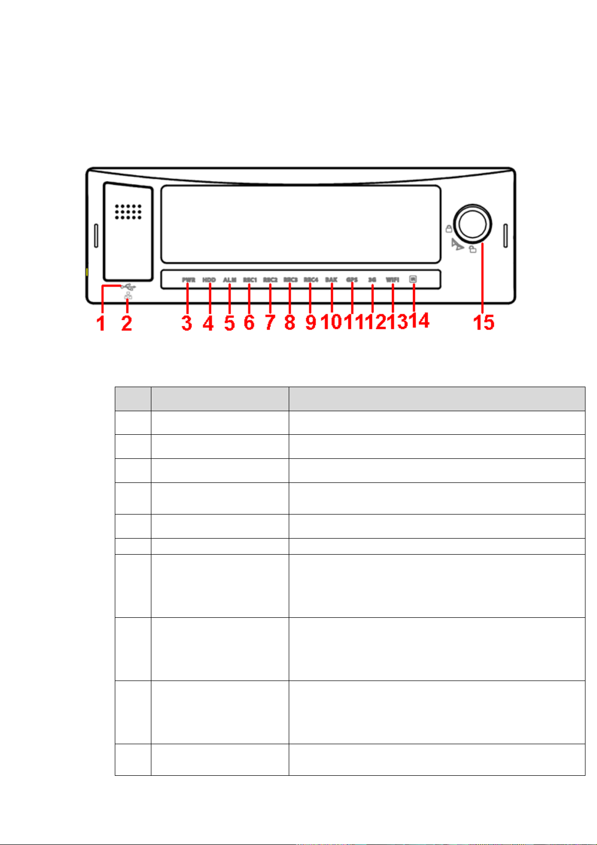
SN
Name
Port name and indicator light
1
USB port
USB port. To connect to mouse, or flash disk to backup data.
2
RJ45 network port
Network port.
3
Power indicator light
The red light is on when the device is running.
4
HDD indicator light
The blue light is on when there is HDD. The light is off when
there is no HDD.
5
Alarm indicator light
There is an alarm when the blue light is on.
6~9
Record indicator light 1~4
The blue light is on when system is recording.
10
Backup indicator light
The blue light is flashing when system is backup.
The blue light is on when the backup is finish.
The light is off when the backup error occurs or the flash
disk is removed.
11
GPS indicator light
Please note only the unit
of GPS module supports
this function.
The blue light is on when GPS function is normal.
12
3G indicator light
Please note only the unit
of 3G module supports
this function.
The blue light is on when 3G function is normal.
13
WIFI indicator light
Please note only the unit
The blue light is on when WIFI function is normal.
2 Front Panel and Rear Panel
2.1 Front Panel
The front panel is shown as in Figure 2-1.
Figure 2-1
Please refer to the following sheet for detailed information.
Page 17
9
SN
Name
Port name and indicator light
of WIFI function supports
this function.
14
Remote control receiver
It is to receive the signal from the remote control.
15
Device lock/unlock (on/off
button)
Please unlock the device before you remove the HDD
box. Otherwise system is going to shut down
automatically.
System can not boot up once the button is unlock.
Please lock the device first and the boot up the device. It
is to save the HDD.
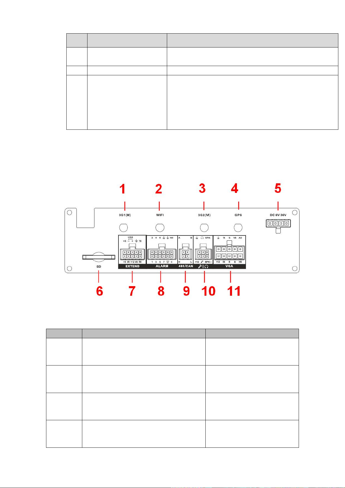
SN
Name
Function
1
3G1 antenna port
Please note only the unit of 3G module
supports this function.
3G antenna port
2
WIFI antenna port
Please note only the unit of WIFI module
supports this function.
WIFI antenna port
3
3G2 antenna port
Please note only the unit of dual-3G
module supports this function.
The second 3G antenna port.(It
is for duak-3G mode only).
4
GPS port
Please note only the unit of GPS module
supports this function.
GPS port
2.2 Rear Panel
2.2.1 Rea Panel
The rear panel is shown as in Figure 2-2.
Please refer to the following sheet for front panel button information.
Figure 2-2
Page 18
10
5
Device power input.
Device power input port.
6
SD card slot
SD card slot
7
Extension port
Extension port. Please refer to
Figure 2-3 for detailed
information.
8
Alarm input/output port
Alarm input/output port, GND
port, and 12V output. Please
refer to chapter 3.7 for detailed
information.
9
RS485 and CAN BUS port.
RS485 communication port. It
can control PTZ.
Reserved port. For data
exchange between vehicles
CAN network and other devices
of CAN port.
10
Audio input and output port.
Bidirectional input and output
port. Please refer to Figure 2-4
for detailed information.
11
VGA port
VGA port It includes all kinds of
VGA signal port. Please refer to
Figure 2-5 for detailed
information.
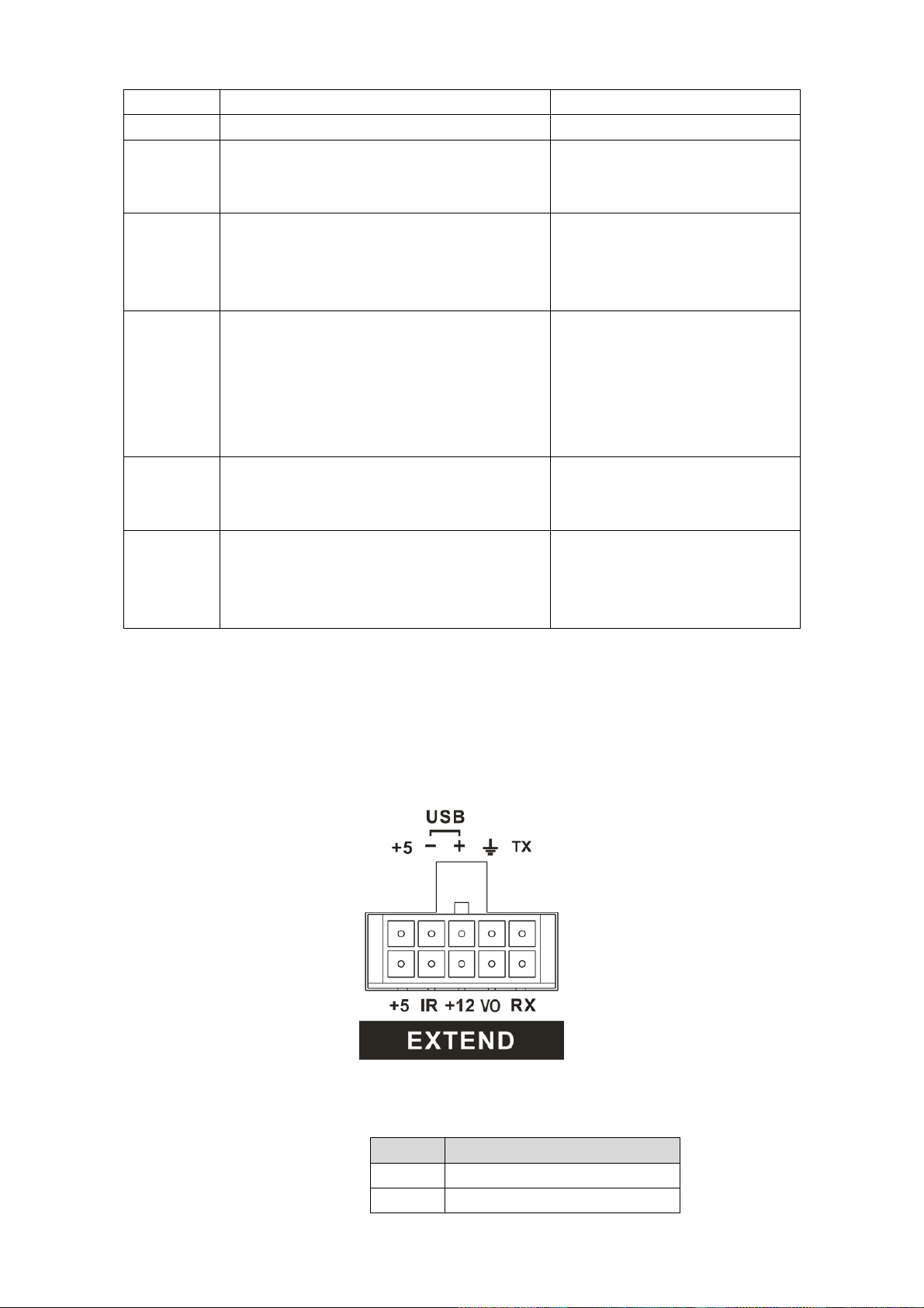
SN
Function
+5
+5V Output (The bottom line)
+5
USB 5V (The top line)
2.2.2 Extension Port
This series has the built-in power; you do not need the mobile power supply sourcing.
The following contents are to introduce function of each port. You can make connection
cable by yourself or you can contact your local retailer to purchase.
The extension port1 is shown as in Figure 2-3.
Figure 2-3
Please refer to the following sheet for detailed information.
Page 19
11
SN
Function
IR
IR receiver port
-
USB data
+12
+12V output
+
USB data+
VO
AV video output
GND
RX
RS232 RX
TX
RS232 TX
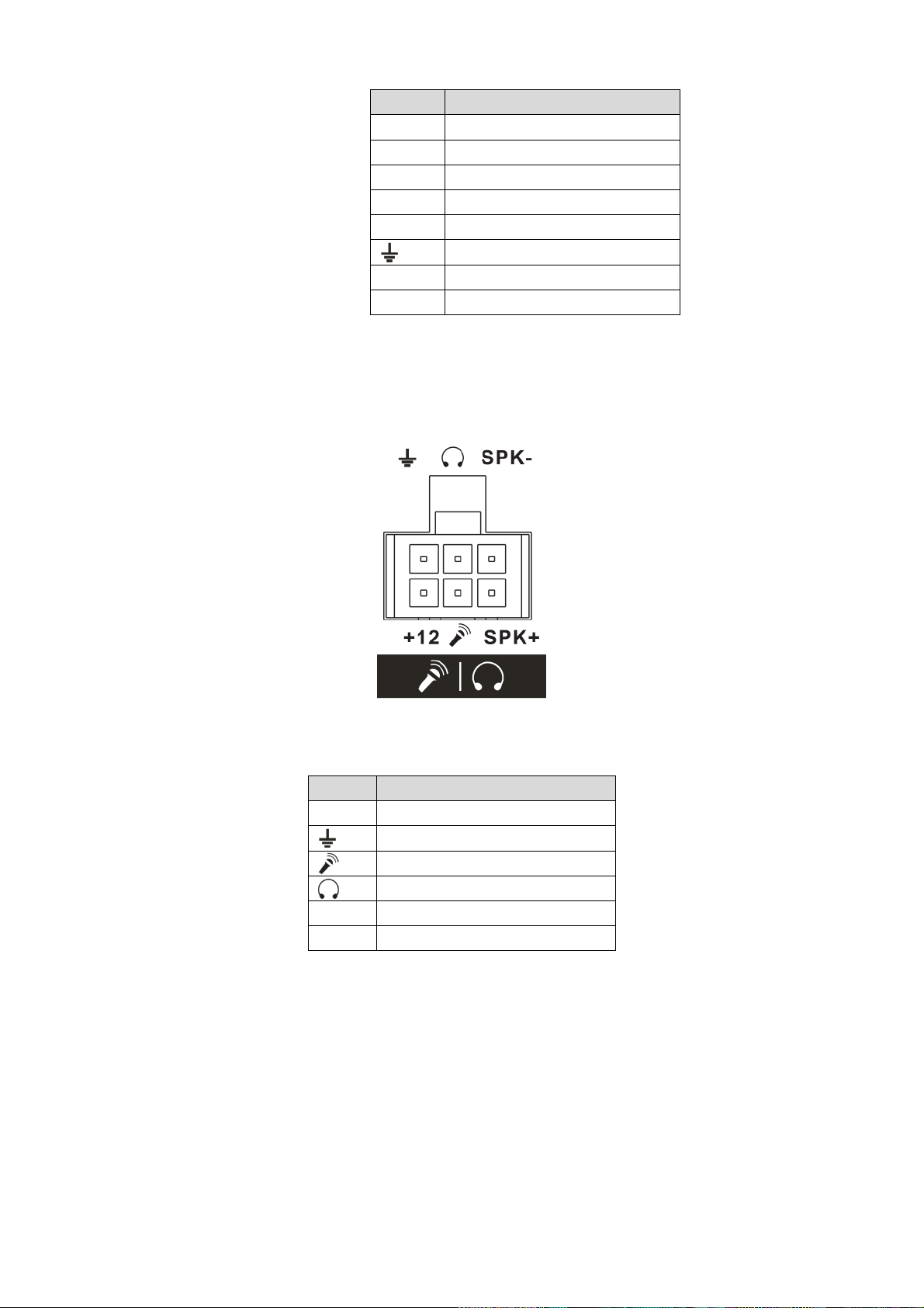
SN
Function
+12
+12V output
GND
Mic In
Mic Out
SPK+
Speak positive
SPK-
Speak negative
2.2.3 Bidirectional talk port
The following contents are to introduce function of each port. You can make connection
cable by yourself or you can contact your local retailer to purchase.
The bidirectional talk port is shown as in Figure 2-4.
Figure 2-4
Please refer to the following sheet for detailed information.
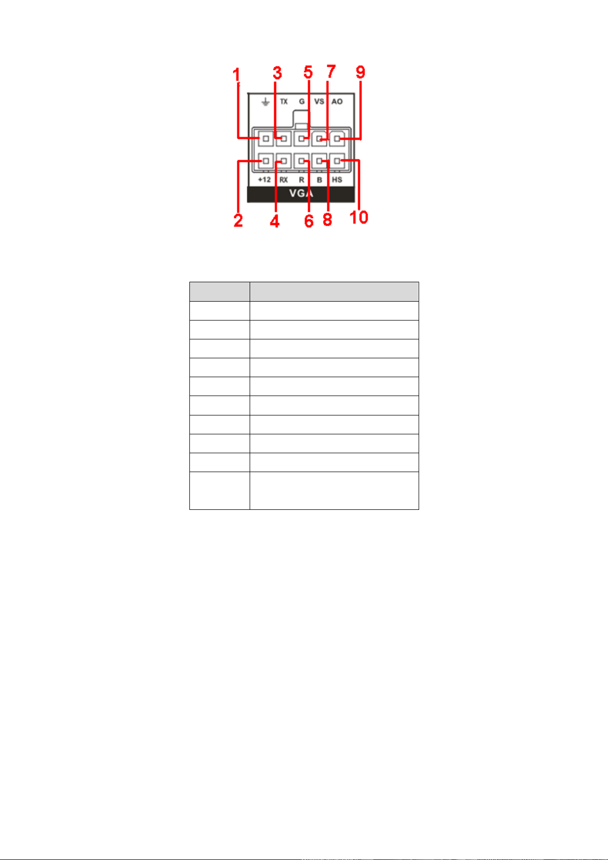
2.2.4 VGA
VGA Port
Page 20
12
SN
Function
1
GND
2
+12V output
3
RXD_232
4
TXD_232
5
VGA signal Green
6
VGA signal Red
7
VGA signal field synchronization
8
VGA signal Blue
9
AV signal video output
10
VGA signal horizontal
synchronization.
Figure 2-5
Please refer to the following sheet for detailed information.
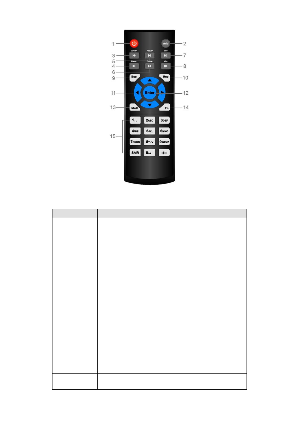
2.3 Remote Control
The remote control interface is shown as in Figure 2-1.
Please note remote control is not our standard accessory and it is not included in the accessory
bag.
Page 21
13
Serial Number
Name
Function
1
Power button
Click it to boot up or shut down
the device.
2
Address
Click it to input device number, so
that you can control it.
3
Forward
Various forward speeds and
normal speed playback.
4
Slow play
Multiple slow play speeds or
normal playback.
5 Next record
In playback mode, playback the
next video.
6 Previous record
In playback mode, playback the
previous video.
7
Play/Pause
In pause mode, click this button
to realize normal playback.
In normal playback click this
button to pause playback.
In real-time monitor mode, click
this button to enter video search
menu.
8 Reverse/pause
Reverse playback pause mode,
click this button to realize normal
Figure 2-1
Please refer to the following sheet for detailed information.
Page 22

14
playback.
In reverse playback click this
button to pause playback.
9 Cancel
Go back to previous menu or
cancel current operation (close
upper interface or control)
10
Record
Start or stop record manually
In record interface, working with
the direction buttons to select the
record channel.
Click this button for at least 1.5
seconds, system can go to the
Manual Record interface.
11
Direction keys
Switch current activated control,
go to left or right.
In playback mode, click up/down
button to switch playback
channel. In 1-window playback
mode, click left/right button to
control playback speed. .
Aux function(such as switch the
PTZ menu, enable/disable reuse
button)
12
Confirm /menu key
go to default button
go to the menu
13
Multiple-window switch
Switch between multiple-window
and one-window.
14
Auxiliary key
In 1-ch monitor mode: pop up
assistant function: PTZ control
and Video color.
Switch the PTZ control menu in
PTZ control interface.
In motion detection interface,
working with direction keys to
complete setup.
In text mode, click it to delete
character.
15
0-9 number key
Input password, channel or
switch channel.
Shift is the button to switch the
input method.
2.4 Mouse Operation
Please refer to the following sheet for mouse operation instruction.
Page 23
15
Left click
mouse
When you have selected one menu item, left click mouse to view menu
content.
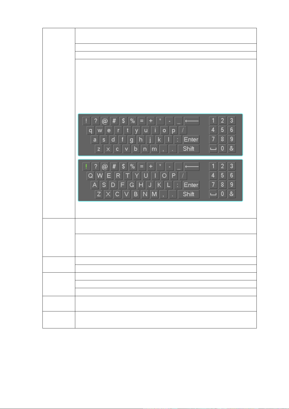
Modify checkbox
Click combo box to pop up dropdown list
In input box, you can select input methods. Left click the corresponding button
on the panel you can input numeral/English character (small/capitalized). Here
← stands for backspace button. _ stands for space button.
In English input mode: _stands for input a backspace icon and ← stands for
deleting the previous character.
In numeral input mode: _ stands for clear and ← stands for deleting the
previous numeral.
Double left
click mouse
Implement special control operation such as double click one item in the file list
to playback the video.
In multiple-window mode, double left click one channel to view in full-window.
Double left click current video again to go back to previous multiple-window
mode.
Right click
mouse
In real-time monitor mode, pops up shortcut menu.
Exit current menu without saving the modification.
Press
middle
button
In numeral input box: Increase or decrease numeral value.
Switch the items in the check box.
Page up or page down
Move
mouse
Select current control or move control
Drag
mouse
Select privacy mask zone.
Page 24

16
3 Installation and Connections
Note: All the installation and operations here should conform to your local electric safety
rules.
3.1 Check Unpacked DVR
When you receive the DVR from the forwarding agent, please check whether there is any visible
damage. The protective materials used for the package of the DVR can protect most accidental
clashes during transportation. Then you can open the box to check the accessories.
Please check the items in accordance with the list (Remote control is optional). Finally you can
remove the protective film of the DVR.
Note
Remote control is not a standard accessory and it is not included in the accessory bag.
3.2 About Front Panel and Rear Panel
For detailed information of the function keys in the front panel and the ports in the rear panel,
please refer to the appendix for detailed information.
The model in the front panel is very important; please check according to your purchase order.
The label in the rear panel is very important too. Usually we need you to represent the serial
number when we provide the service after sales.
3.3 HDD/SIM Card Installation
3.3.1 HDD Installation
Important
Shut down the device and unplug the power cable before install/remove the HDD.
The e-lock on the right side of the front panel shall be unlocked when you install/remove the
HDD. Please lock the button before you boot up the device.
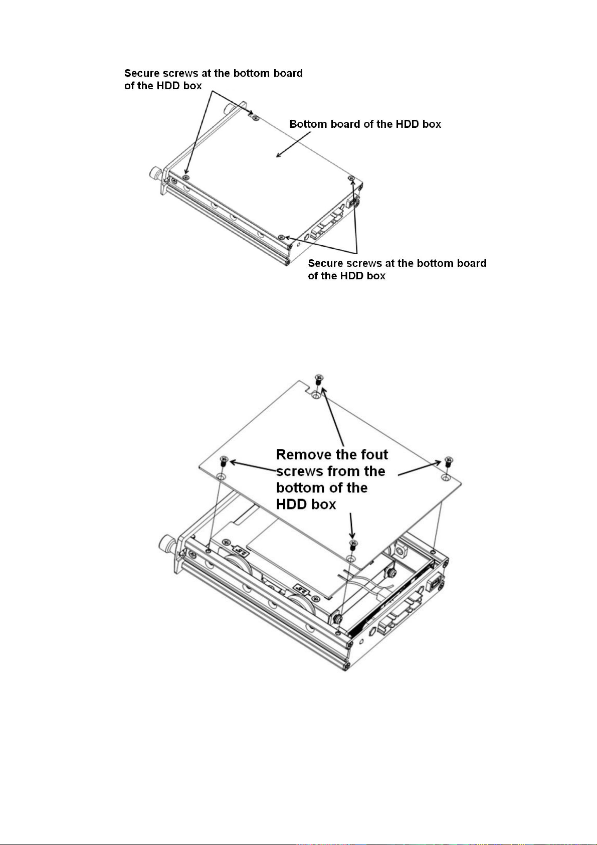
The unit you received has no HDD. Please remove the HDD box from the device and then follow
the steps listed below to install.
1) The HDD box and the parts are shown as below. See Figure 3-1. It includes bottom board of
the HDD box and screws.
Page 25
17
Figure 3-1
2) Please loosen the screws of the bottom board of the HDD box and then remove the bottom
board. Now you can see an interface shown as in Figure 3-2.
Figure 3-2
3) Now you can see an interface shown as in Figure 3-3. Use four screws to secure the HDD on
the bracket and then use two screws to fasten the bracket on the bottom board.
Page 26

18
Figure 3-3
3.3.2 SIM Card Installation
This series product supports built-in SIM card. See Figure 3-4.
Remove the HDD box and then open the SIM card slot. Insert the SIM card and then close the
cover.
Figure 3-4
3.4 Connecting Power Supply
Please check input voltage and device power button match or not.
We recommend you use UPS to guarantee steady operation, DVR life span, and other peripheral
equipments operation such as cameras.
3.5 Connecting Audio/Video Input and Output Devices
3.5.1 Connecting Video Input
The input video format includes: composite signal PAL/NTSC 1.0VB
P- P 75Ω
.
Page 27
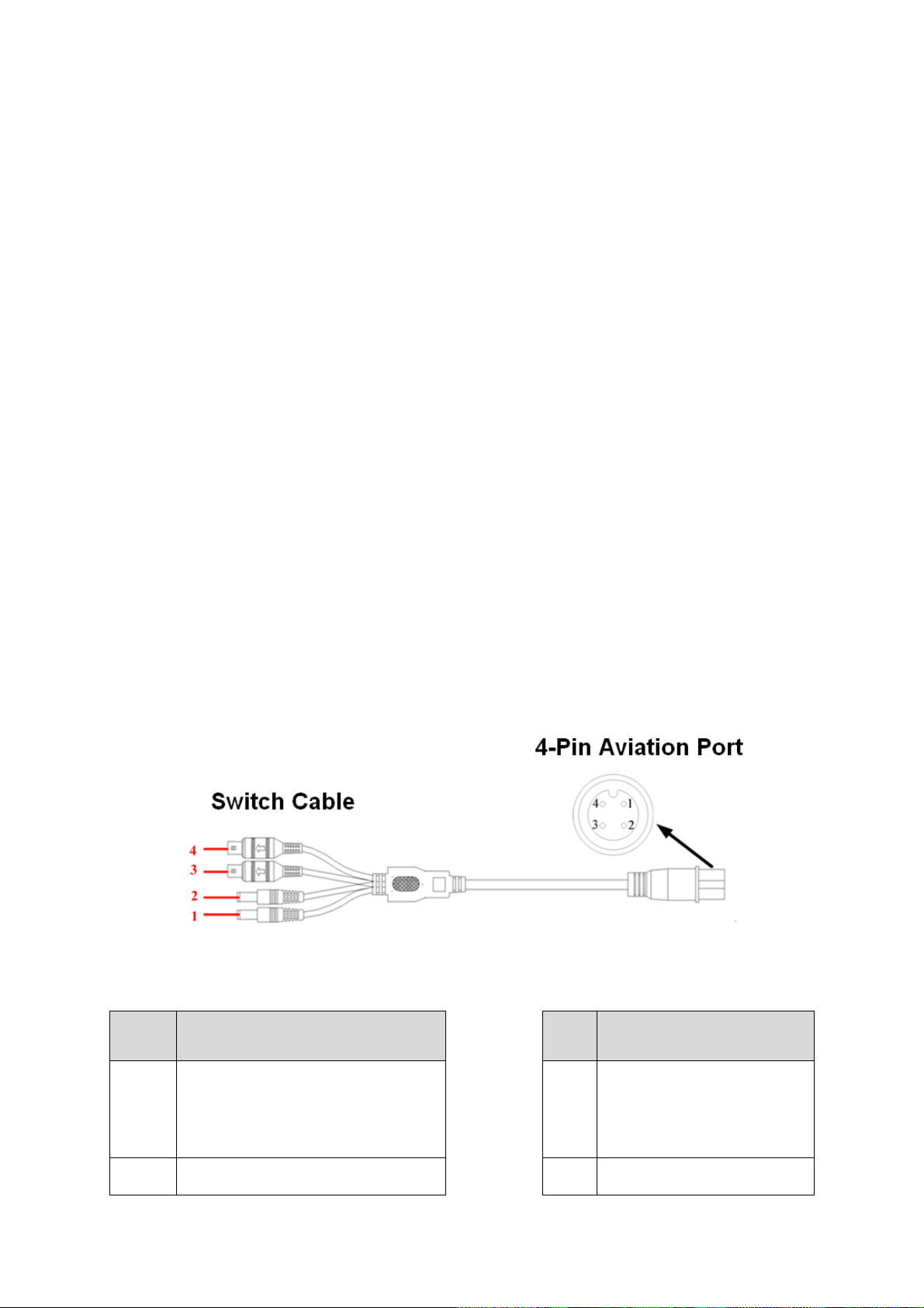
19
Socket
Switch cable color and
definition
Port
4-pin aviation port
1
DC power male socket. External is
negative and internal is positive.
(Camera power)
1 12V external camera power
2
DC power male socket. External is
2 GND
The video signal should comply with your national standards.
The input video signal shall have high SNR, low distortion; low interference, natural color and
suitable lightness.
Guarantee the stability and reliability of the camera signal:
The camera shall be installed in a cool, dry place away from direct sunlight, inflammable,
explosive substances and etc.
The camera and the DVR should have the same grounding to ensure the normal operation of the
camera.
Guarantee stability and reliability of the transmission lineBTTTB
Please use high quality, sound shielded BNC. Please select suitable BNC model according to the
transmission distance.
If the distance is too long, you should use twisted pair cable, and you can add video compensation
devices or use optical fiber to ensure video quality.
You should keep the video signal away from the strong electromagnetic interference, especially
the high tension current.
Keep connection lugs in well contactBTTTB
The signal line and shielded wire should be fixed firmly and in well connection. Avoid dry joint, lap
welding and oxidation.BTTTB
3.5.2 Audio Input
Due to high impedance of audio input, please use active sound pick-up.
Audio transmission is similar to video transmission. Try to avoid interference, dry joint, loose
contact and it shall be away from high tension current.
3.5.3 Audio/Video Input Switch Cable
Please use the following audio/video input cable if your camera port is BNC.
Please refer to Figure 3-5 for 4-pin aviation port cable information.
Please refer to the following sheet for detailed information.
Figure 3-5
Page 28
20
Socket
Switch cable color and
definition
Port
4-pin aviation port
negative and internal is positive.
(Camera power)
3
Yellow BNC male port ( Video
input)
3 Audio
4
White BNC male port(Audio input)
4 Video
3.6 Connecting Audio/Video Output and Output Devices
3.6.1 Connecting Video Output
Video output includes a BNC(PAL/NTSC1.0V
BNC and VGA output at the same time.
When you are using pc-type monitor to replace the monitor, please pay attention to the following
points:
To defer aging, do not allow the pc monitor to run for a long time.
Regular demagnetization will keep device maintain proper status.
Keep it away from strong electromagnetic interference devices.
Using TV as video output device is not a reliable substitution method. You also need to reduce the
working hour and control the interference from power supply and other devices. The low quality
TV may result in device damage.
3.6.2 Audio Output
The audio output signal parameter is usually over 200mv 1KΩ (BNC). It can directly connect to
low impedance earphone, active sound box or amplifier-drive audio output device.
If the sound box and the pick-up cannot be separated spatially, it is easy to arouse squeaking. In
this case you can adopt the following measures:
Use better sound pick-up with better directing property.
Reduce the volume of the sound box.
Using more sound-absorbing materials in decoration can reduce voice echo and improve
acoustics environment.
Adjust the layout to reduce happening of the squeaking.
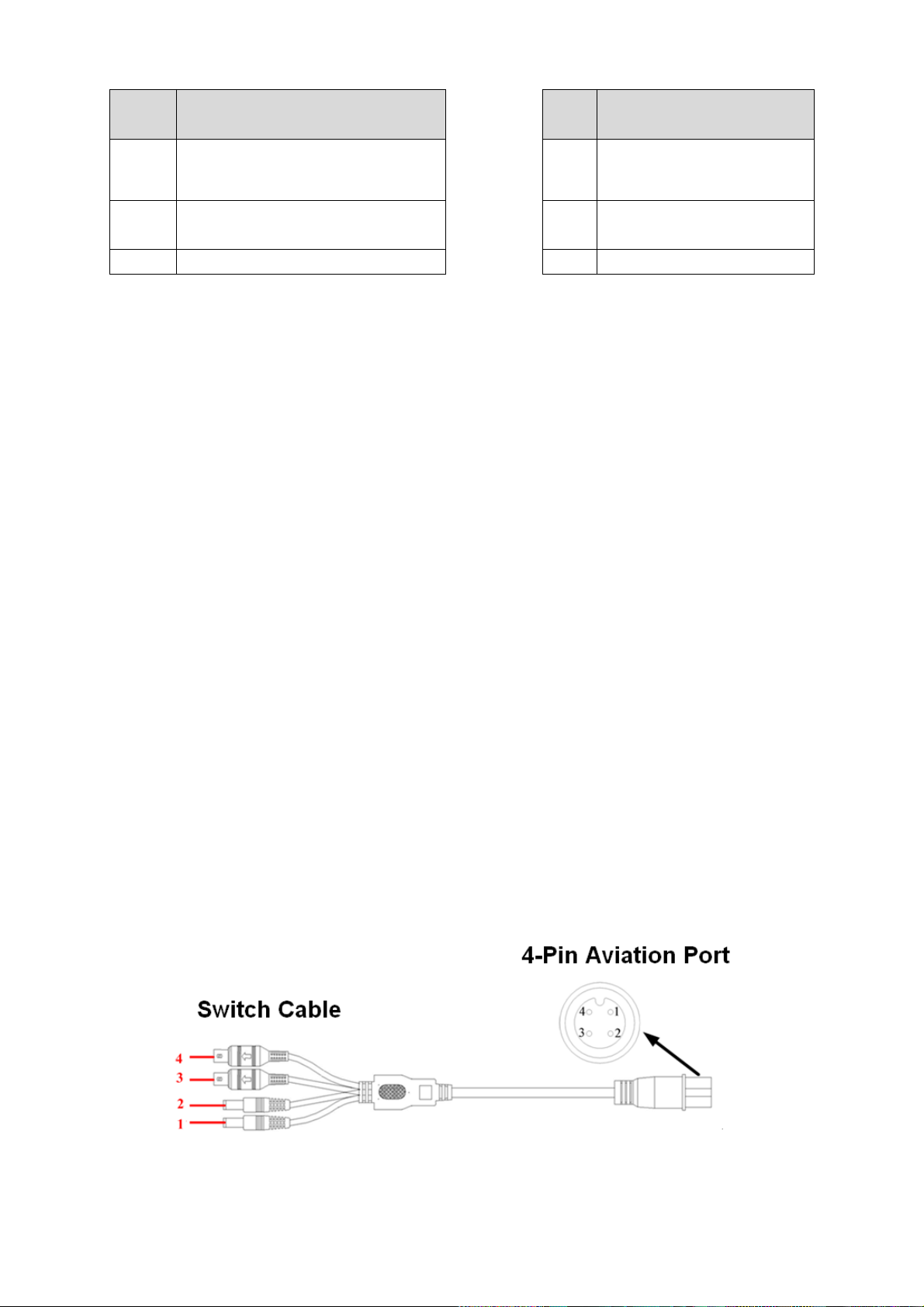
3.6.3 Audio/Video Output Switch Cable
Audio/video output cable is shown as below. See Figure 3-6. You can use it when your monitor
port is general BNC port.
,75Ω)output ,a VGA output. System supports
P-P
Please refer to the following sheet for detailed information.
Figure 3-6
Page 29

21
Socket
Switch cable color and
definition
Port
4-pin aviation port
1
DC power male socket. External is
negative and internal is positive.
(Camera power)
1 12V external camera power
2
DC power male socket. External is
negative and internal is positive.
(Camera power)
2 GND
3
Yellow BNC male port ( Video
input)
3 Audio
4
White BNC male port(Audio input)
4 Video
Note
For some special series products, you need contact your local retailer for additional audio/video
output cable.
3.7 Alarm Input and Output Connection
There are two alarm input types for you to select: normal open (NO) and normal close (NC).
1. Alarm input
a. Alarm input supports grounding alarm input.
b. Alarm input 1-16 supports 12V voltage signal alarm input.
c. When the alarm device is connecting one DVR and one other device, please use a relay to
separate them,
2. Alarm output
a. Ensure the decoder has the same grounding with DVR, otherwise you may not control the PTZ.
Shielded twisted wire is recommended and the shielded layer is used to connect to the grounding.
b. Avoid high voltage. Ensure proper wiring and some thunder protection measures.
c. For too long signal wires, 120Ω should be parallel connected between A, B lines on the far end
to reduce reflection and guarantee the signal quality.
d. “485 A, B” of DVR cannot parallel connect with “485 port” of other device.
e. The voltage between of A,B lines of the decoder should be less than 5v.
3. PTZ decoder connection
Support 2-channel analog signal level input. <0}
4. Please make sure the front-end device has soundly earthed.
Improper grounding may result in chip damage.
3.7.1 Alarm Input and Output Details
Alarm input and output interface is shown as in Figure 3-7.
Page 30
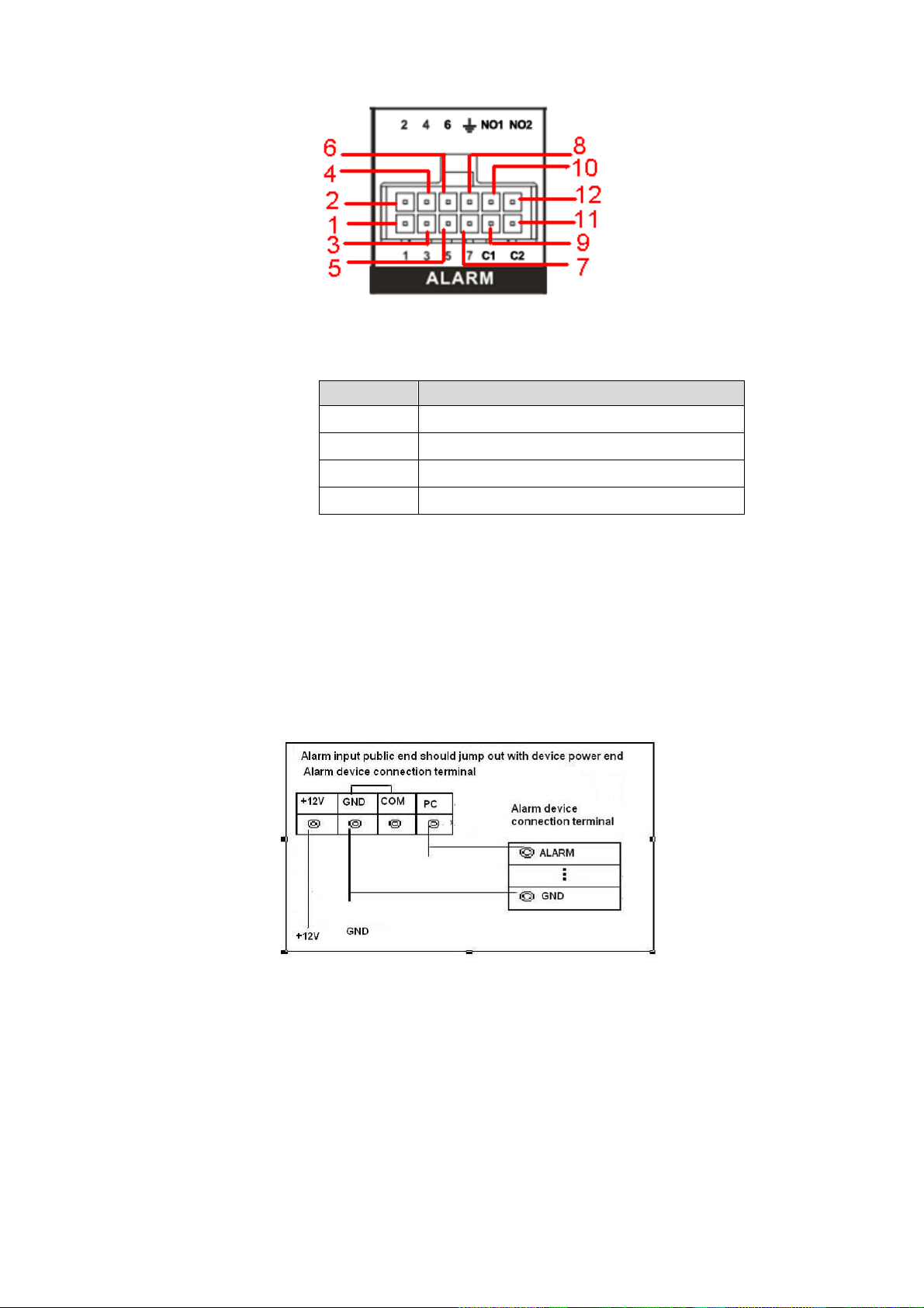
22
Name
Pin Introduction
1~7
Alarm input 1~Alarm input 7
8
Alarm GND
9/11
NC1/NC2 of alarm output 1/2
10/12
NO1/NO2 of alarm output 1/2
Figure 3-7
Please refer to the following sheet for detailed information.
3.7.2 Alarm Input Port
Please refer to the following sheet for more information. See Figure 3-8.
Normal open or Normal close type.
Please parallel connect COM end and COM end of the alarm detector (Provide external
power to the alarm detector).
Please parallel connect the Ground of the DVR and the ground of the alarm detector.
Please connect the NC port of the alarm sensor to the DVR alarm input(ALARM)
Use the same ground with that of DVR if you use external power to the alarm device.
3.7.3 Alarm Output Port
Alarm output 1/2 is level input, output voltage is 12V. The max load shall be less than 12V/1A.
It should not be connected to high power load directly to avoid high current which may result
in relay damage. Please use the co contactor to realize the connection between the alarm
output port and the load.
To avoid overloading, please read the following relay parameters sheet carefully.
Figure 3-8
Relay Specification
Page 31

23
Model: HFD23
Contact
Parameter
Contact mode
1Z
Contact resistance
100mΩ(0.1A 6VDC)
Contact material
AgNi+gold-plating
Contact
0.5A 125VAC/1A 30VDC
Max switch voltage
125VAC / 60VDC
Max switch current
2A
Max switch power
62.5VA/30W
Min allowed load
1mA 5V
Mechanical durability
1x10⁷(300/min)
Electric durability
1x10⁵(30/min)
Performance
Parameter
Insulation resistance
1000MΩ(500VDC)
Media
pressure
Between
loop and
1000VAC 1min
Between
separated
contact
400VAC 1min
Operation time (Rated
voltage))
≤5ms
Release time (Rated
voltage)
≤5ms
Bound time (Rated
voltage)
About 5ms
Loop temperature
rise(Rated voltage)
≤65K
Strike
98m/s2
Vibration
10Hz~55 Hz 3.3mm Double amplitude
Humidity
98% RH, 40℃
Temperature
-30℃~70℃
Weight
About 2.2g
leading-out end mode
DIP
Seal mode
Sealed
Loop
Rated Loop Power
Standard mode:200mW; Sensitivity mode:
150mW
Page 32

24
4 Operation
4.1 Boot up& Shutdown
The buzzer beeps once after system successfully booted up.
You can see the corresponding record status indictor light if system is recording after booted up.
The system can automatically backup video and resume previous working status after power
outage.
4.1.1 Boot up
Turn the key to ACC, you can see power indicator light becomes on and DVR boots up (DVR
boots up might take several seconds). After booted up, system is in multiple-window mode and
schedule record status (Chapter 4.9.3) by default. The record indicator light becomes on too if the
device is in the record period.
In the default setup, the device will automatically shut down after the ACC power is
disconnected.
The ACC delay value ranges from 0 to 65535 (Unit: minute). System can delay shutting down
for the specified time and then turn off(Main menu->Advanced->Auto maintenance).
4.1.2 Schedule Boot up & Shutdown
System enables schedule record function if the boot up is within the specified period. You can
see the corresponding record indicator light becomes on and system runs normally.
4.2 Startup Wizard
After system booted up, system pops up the startup wizard.
Click the Cancel button; you can go to the system login interface.
Click the Next Step button; you can login first and then go to the startup wizard interface. Here you
can set the system basic information. See Figure 4-1.
Figure 4-1
Page 33

25
SN
Icon
1
Display plate number.
For detailed setup information, please refer to chapter 4.9.1 General.
2
Display device working temperature.
3
Display current vehicle speed.
4
Display system time and date.
5
Network icon. It includes WIFI, 3G, GPRS, DSS platform.
6
Current longitude and latitude.
7
: Video loss occurs.
8
Current channel is recording now.
4.3 Login
You can see login interface. See Figure 4-2.
System consists of three accounts. You can refer to chapter 4.10.4 Account for detailed operation
information.
Username: admin. Password: admin. (administrator, local and network)
Username: 888888. Password: 888888. (administrator, local only)
Username: default. Password: default(hidden user)
You can use USB2.0 mouse to input. Click to switch between numeral, English character
(small/capitalized) and denotation.
Note:
For security reason, please modify password after you first login.
Continuous three times login failure will result in system alarm and five times login failure will
result in account lock.
Figure 4-2
4.4 Preview
After you successfully logged in, you can go to preview interface directly. See Figure 4-3. You can
overlay the corresponding date, time and channel name on each screen. You can refer to the
following sheet for detailed information.
Page 34

26
Figure 4-3
4.5 Right-Click Menu
On the preview interface, right click mouse, you can view menu interface shown as in Figure
4-4.
Figure 4-4
4.5.1 Window Switch
System supports 1/4-window. You can select from the dropdown list. See Figure 4-5.
Page 35

27
Figure 4-5
4.5.2 PTZ Control
Before you go to PTZ control interface, please go to chapter 4.9.8 to set PTZ parameter. See
Figure 4-6.
Figure 4-6
4.5.3 Color
Here you can set hue, brightness, contrast, saturation, gain, white level, color mode and etc.
See Figure 4-7.
Figure 4-7
4.5.4 Search
Page 36

28
Please refer to chapter 4.6.
4.5.5 Record Control
Please refer to chapter 4.10.3.
4.5.6 Alarm Output
Please refer to chapter 4.10.2.
4.5.7 Zero-channel encoding
Please refer to chapter 4.9.9.
4.5.8 Main Menu
After you logged in, the system main menu is shown as below. See Figure 4-8. There are total
seven icons: search, Information, vehicle, setting, backup, advanced and shutdown. Move the
cursor to highlight the icon, then double click mouse to enter the sub-menu.
Figure 4-8
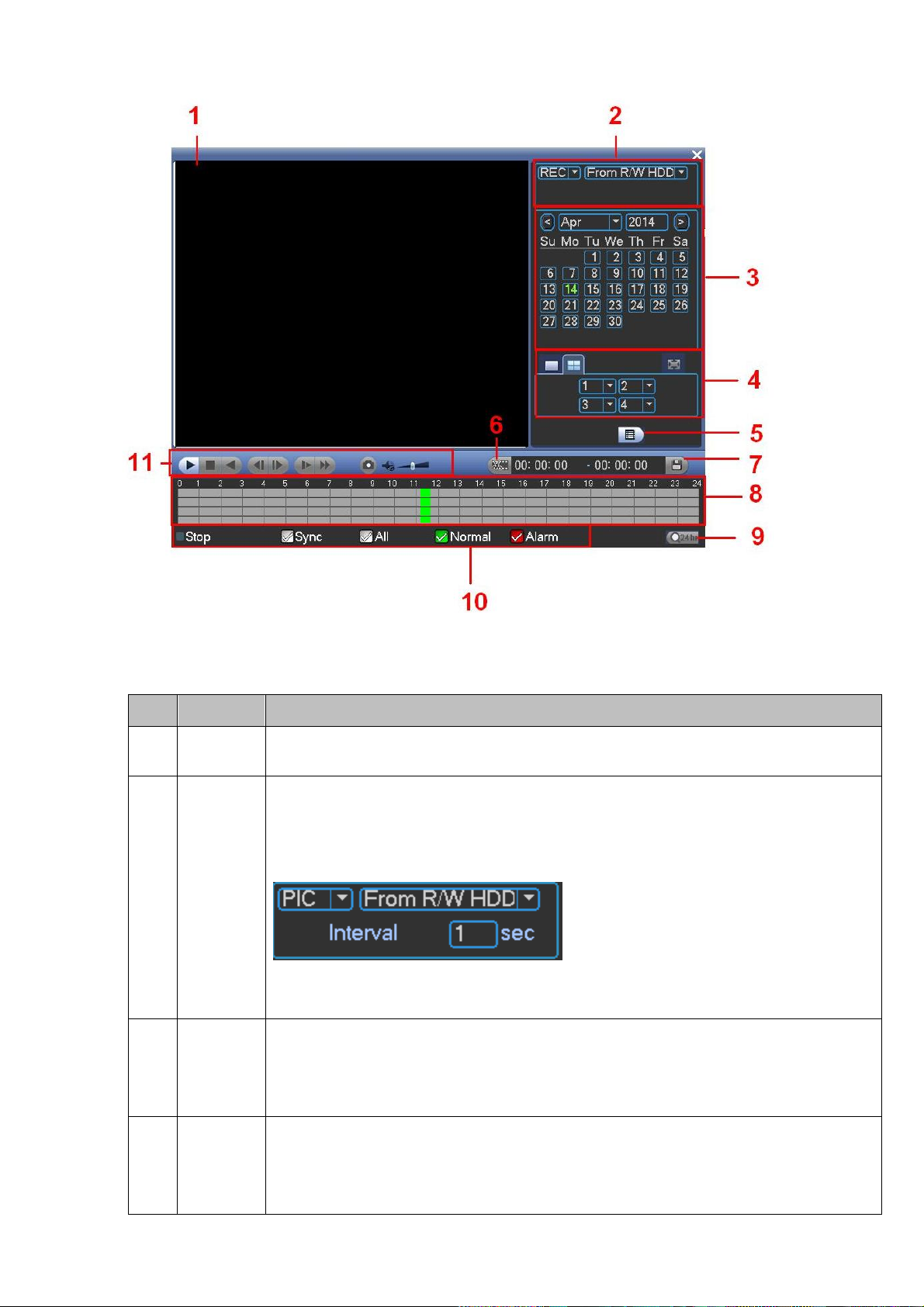
4.6 Search & Playback
Click search button in the main menu, search interface is shown as below. See Figure 4-9.
Page 37
29
SN
Name
Function
1
Display
window
Here is to display the searched picture or file.
Support 1/4-window playback.
2
Search
type
Here you can select to search the picture or the recorded file.
You can select to play from the read-write HDD, from I/O device.
The interface is shown as below if you want to search a picture. You can set
activation interval. See Figure 4-10.
Figure 4-10
3
Calendar
The blue highlighted date means there is picture or file. Otherwise, there is no
picture or file.
In any play mode, click the date you want to see, you can see the
corresponding record file trace in the time bar.
4
Playback
mode
and
channel
Playback mode:1/4.
In 1-window playback mode: you can select 1-4(8) channels.
In 4-window playback mode: you can select 4 channels according to your
requirement.
Figure 4-9
Please refer to the following sheet for more information.
Page 38

30
selection
pane.
The time bar will change once you modify the playback mode or the channel
option.
5
File list
switch
button
Double click it; you can view the picture/record file list of current day.
The file list is to display the first channel of the record file.
The system can display max 128 files in one time. Use the / or the mouse
to view the file. Select one item, and then double click the mouse or click the
ENTER button to playback.
You can input the period in the following interface and click button to
begin accurate search.
File type:R—regular record; A—external alarm record.
Lock file. Click the file you want to lock and click the button to lock. The
file you locked will not be overwritten.
Search locked file: Click the button to view the locked file.
Return: Click button , system goes back to the calendar and channel setup
interface.
6
Clip
Please refer to chapter 5.10 for detailed information.
7
Save
8
Time bar
Display current record type and its corresponding period.
9
Time bar
unit
The option includes: 24H, 12H, 1H and 30M. The smaller the unit, the larger
the zoom rate. You can accurately set the time in the time bar to playback the
record.
The time bar is beginning with 0 o'clock when you are setting the configuration.
The time bar zooms in the period of the current playback time when you are
playing the file.
10
Record
type
There are three modes: Alarm/regular/all.
In any play mode, the time bar will change once you change record type.
11
Playback
control
pane.
►/
Play/Pause
There are three ways for you to begin playback.
The play button
Double click the valid period of the time bar.
Double click the item in the file list.
In slow play mode, click it to switch between play/pause.
■
Stop
Backward play
In normal play mode, left click the button, the file begins backward play.
Click it again to pause current play.
In backward play mode, click ►/ to restore normal play.
Page 39

31
│/
│
In playback mode, click it to play the next or the previous section. You can
click continuously when you are watching the files from the same channel.
In normal play mode, when you pause current play, you can click │ and
│ to begin frame by frame playback.
In frame by frame playback mode, click ►/ to restore normal playback.
►
Slow play
In playback mode, click it to realize various slow play modes such as slow
play 1, slow play 2, and etc.
Fast forward
In playback mode, click to realize various fast play modes such as fast
play 1,fast play 2 and etc.
Note: The actual play speed has relationship with the software version.
The volume of the playback
Click the snapshot button in the full-screen mode, the system can snapshot
1 picture per second.
System supports custom snap picture saved path. Please connect the
peripheral device first, click snap button on the full-screen mode, you can
select or create path. Click Start button, the snapshot picture can be saved
to the specified path.
Other Functions
13
Other channel
synchronization switch to play
when playback
When playing the file, click the number button, system can
switch to the same period of the corresponding channel to play.
14
Digital zoom
When the system is in full-screen playback mode, left click
the mouse in the screen. Drag your mouse in the screen to
select a section and then left click mouse to realize digital
zoom. You can right click mouse to exit.
Note:
All the operations here (such as playback speed, channel, time and progress) have
relationship with hardware version. Some series DVRs do not support some functions or
playback speeds.
4.7 Information
Here is for you to view system information. There are total eight items: HDD (hard disk
information), BPS (data stream statistics), log, Version, online user, device, network test, network
load. See Figure 4-11.
Page 40

32
Figure 4-11
4.7.1 HDD Information
Here is to list hard disk type, total space, free space, and status. See Figure 4-12.
○ means current HDD is normal.. - means there is no HDD.
If disk is damaged, system shows as “?”. Please remove the broken hard disk before you add a
new one.
Once there is a hard disk confliction, please check hard disk time and system time is the same or
not. Please go to setting then general to modify system time. At last, reboot the system to solve
this problem.
After system booted up, if there is any confliction, system goes to HDD information interface
directly. Please note, system does not ask you to deal with it forcedly.
Figure 4-12
Page 41

33
Parameter
Function
SATA
1-2 here means system max supports 2 HDDs.
When HDD is working properly, system is shown as O. . “_” means there is
no HDD.
SN
You can view the HDD amount the device connected to;
﹡ means the second HDD is current working HDD.
Type
The corresponding HDD property.
Total space
The HDD total capacity.
Free space
The HDD free capacity.
Status
HDD can work properly or not.
Bad track
Display there is bad track or not.
Page up
Click it to view previous page.
Page down
Click it to view the next page.
View
recording time
Click it to view HDD record information (file start time and end time).
View HDD
type and
capability
Click it to view HDD property, status and etc,
4.7.2 BPS
Here is for you to view current video data stream (Kb/S) and occupied hard disk storage (MB/h).
See Figure 4-13.
Figure 4-13
Page 42

34
4.7.3 Log
Here is for you to view system log file. System lists the following information. See Figure 4-14.
Log types include system operation, configuration operation, data management, alarm event,
record operation, account management, log clear, file operation and etc.
Start time/end time: Pleased select start time and end time, then click search button. You can
view the log files in a list. System max displays 100 logs in one page. It can max save 1024
log files. Please use page up/down button on the interface or the front panel to view more.
Backup: Please select a folder you want to save; you can click the backup button to save the
log files. After the backup, you can see there is a folder named Log_time on the backup path.
Double click the folder, you can see the log file
Details: Click the Details button or double click the log item, you can view the detailed
information. See Figure 4-15. Here you can use rolling bar to view information, or you can
use Page up/Page down to view other log information.
Figure 4-14
Figure 4-15
Page 43

35
4.7.4 Version
Here is for you to view some version information. See Figure 4-16.
System version:
Build Date
Web
Serial number
Model
Upgrade
Start: Please insert the USB device that have the update file to the device and then click the
Start button to begin the update. See Figure 4-17.
Important
Please make sure the upgrade file name shall be update.bin.
Figure 4-16
Figure 4-17
Page 44

36
4.7.5 Device
Here you can view some device basic information. See Figure 4-18.
Figure 4-18
4.7.6 Online Users
Here is for you manage WEB online users connected to the local device. See Figure 4-19.
You can disconnect one user or block one user if you have proper system right.
Figure 4-19
4.7.7 Network Test
Network test interface is shown as in Figure 4-20.
Destination IP: Please input valid IPV4 address and domain name.
Test: Click it to test the connection with the destination IP address. The test results can display
average delay and packet loss rate and you can also view the network status as OK, bad, no
connection and etc.
Page 45

37
Network Sniffer backup: Please insert USB2.0 device and click the Refresh button, you can view
the device on the following column. You can use the dropdown list to select peripheral device.
Click Browse button to select the snap path. The steps here are same as preview backup
operation.
Figure 4-20
4.7.8 Network Load
Network load is shown as in Figure 4-21. Here you can view the follow statistics of the device
network adapter. The green wave is send out speed and red wave is receive speed.
Figure 4-21
4.8 Vehicle
The vehicle interface is shown as below. See Figure 4-22. It includes seven buttons:
3G/Wifi/G-sensor/register/maintain/abnormal/TV adjust.
Page 46

38
Figure 4-22
4.8.1 3G
3G setup interface is shown as below. See Figure 4-23.
Please follow the steps listed below to set.
a) Boot up 3G module and then check the 3G Enable box to enable this function.
b) Please set AUTH, dial number, user name, and password. Please contact the VPN
administrator or your 3G service provider for detailed setup information.
c) 3G network is to connect to a platform so that you can view vehicle real-time information
such as real-time video, driver status, vehicle position and etc.
d) The WIFI has the higher priority than the 3G network when these two signals are available
at the same. In this situation, the device uses WIFI network by default and disconnect 3G
network.
e) If you find the 3G module can not connect to the platform after dial. Please refer to the FAQ
or contact your local retailer for help.
Please refer to the following contents for the parameter information.
Pane 1: Display 3G signal intensity after you enabled 3G function.
Pane 2: Display 3G module configuration information after you enabled 3G function.
Pane 3: Display 3G module status information after you enabled 3G function.
It is to display current wireless network signal intensity such as EVDO, CDMA1x, WCDMA,
WCDMA, EDGE and etc.
3G network: It is to display current wireless network adapter name.
3G Enable/Disable: Check the box here to enable 3G module.
Network type: There are various network types for different 3G network modules. You can
select according to your requirements.
APN: It is the wireless connection server. It is to set you access the wireless network via
which method.
AUTH: It is the authentication mode. It supports PAP/CHAP/ NO AUTH.
Dial number: Please input 3G network dialup number you got from your ISP.
Page 47

39
1
2
3
User name: It is the user name for you to login the 3G network.
Password: It is the password for you to login the 3G network.
3G wireless network: Here is to display wireless network status, SIM card status, dial status.
If the 3G connection is OK, then you can see the device IP address the wireless network
automatically allocates.
Figure 4-23
3G flow control: It is to show the 3G flow you used. See Figure 4-24.
Figure 4-24
4.8.2 WIFI
The WIFI interface is shown as below. See Figure 4-25.
Please follow the steps listed below to set.
a) Boot up a WIFI module and then check the Auto Connect WIFI box to enable WIFI function.
b) In Figure 4-25, click Refresh button to view the entire WIFI signals available.
c) Double click a WIFI signal on the list, you can see the WIFI connection dialogue box.
d) Select the corresponding verification type. Please contact your network administrator if you
do not know how to select the type here. The WIFI connection shall set proper password.
Page 48

40
Usually we recommend the verification type as WPA2-PSK instead of WEP..
e) Input WIFI connection password.
f) Please select DHCP if your WIFI is to auto allocate IP address. Please set the
corresponding IP/subnet mask/gateway if your WIFI needs a specified IP.
g) Please note you must set WIFI priority when you set. The priority ranges from 1 to 5 and the
5 has the highest priority. When there are several WIFI signals available, system can try to
connect one by one according to the priority setup.
h) Please click Save button to save the setup and then click Connect button to connect
manually.
i) After you save WIFI hotspot setup, you can view it on the static setup interface. After device
booted up, system can auto connect to the hotspot you set at the static setup interface once
the Auto connect WIFI box is checked.
j) Please disconnect WIFI connection before you modify WIFI network parameter. Do not
modify WIFI setup when it is online.
Figure 4-25
WIFI Connection and Disconnection
Double click one hotspot; system goes to WIFI connection interface. See Figure 4-26. Please
input password and click Connect button. System needs to turn off current connection and then
connect to a new hotspot, if there is a connection.
Page 49

41
Figure 4-26
After successfully connection, you can see the following interface. You can see it is connected
now. See Figure 4-27.
Figure 4-27
After setup, you can click Save button to add it to the hotspot setup list. Besides, you can double
click a hotspot on the hotspot real-time list and input password, and then click Save button to save
it to the hotspot setup list.
Device auto connects to hotspot
After device booted up (WIFI function is enabled), device can automatically connect to the hotspot
according to priority on the hotspot setup list. System stops until it successfully connects to one
hotspot. Device is in the hotspot connection status if there is no saved hotspot within current
range.
Delete: It can delete a hotspot from the hotspot setup list.
WIFI working information: After system successfully connected to WIFI, you can view hotspot
name, IP address, subnet mask, default gateway and etc. See Figure 4-28.
Note:
On the static setting interface (Figure 4-27), only the hotspot of WEB authentication mode
can supports key-index.
The hotspot setup list max can save 5 hotspots. The highest priority is 5. The priority shall be
unique.
System does not support connect to hotspot of OPEN encryption mode.
The Static setting does not support the SSID of open verification type.
System can switch between WIFI and 3G freely. You can enable WIFI and 3G network at the
same time. WIFI connection has the higher priority. System automatically connects to 3G
network if the WIFI connection failed.
Page 50

42
Figure 4-28
4.8.3 G-Sensor
The G-Sensor interface is shown as in Figure 4-29. Here you can set device orientation and
sensitivity.
Figure 4-29
4.8.4 Register
This function allows the device to auto register to the proxy you specified. In this way, you can use
the client-end to access the DVR and etc via the proxy. Here the proxy has a switch function. In
the network service, device supports the server address of IPv4 or domain.
Please follow the steps listed below to use this function.
Please set proxy server address, port, and sub-device name at the device-end. Please enable the
Page 51

43
auto register function, the device can auto register to the proxy server.
1) The setup interface is shown as in Figure 4-30.
Important
Do not input network default port such as TCP port number.
Figure 4-30
2) The proxy server software developed from the SDK. Please open the software and input the
global setup. Please make sure the auto connection port here is the same as the port you set in
the previous step.
3) Now you can add device. Please do not input default port number such as the TCP port in the
mapping port number. The device ID here shall be the same with the ID you input in Figure 4-30.
Click Add button to complete the setup.
4) Now you can boot up the proxy server. When you see the network status is Y, it means your
registration is OK. You can view the proxy server when the device is online.
Important
The server IP address can also be domain. But you need to register a domain name before you
run proxy device server.
4.8.5 Auto Maintenance
Here you can set auto-reboot time and auto-delete old files, auto shutdown, and auto ACC delay
(0-65535 minutes) setup. You can set to delete the files for the specified days. See Figure 4-31.
After all the setups please click save button, system goes back to the previous menu.
Note
The auto boot up and ACC delay function is only valid when vehicle ACC signal connection is OK.
The auto shut down has higher priority than ACC delay. If you enable these two functions at the
same time, the ACC delay function is null.
System default setup is to restart on each 2:00 Tuesday.
Page 52

44
Figure 4-31
4.8.6 Abnormal
Abnormal interface is shown as in Figure 4-32 and Figure 4-33.
Event type: There are several options for you such as disk error, no disk, no space, high
temperature, low battery, overspeed, low speed and etc. (multiple choices).
Enable: Check the box here to enable this function.
Alarm output: Please select alarm activation output port (multiple choices).
Less than: You can set HDD threshold here so that system can alert you once the HDD
space is lower than the threshold here.
Latch: Here you can set corresponding delaying time. The value ranges from 1s-300s.
System automatically delays specified seconds in turning off alarm and activated output after
external alarm cancelled.
Show message: system can pop up the message in the local screen to alert you when an
alarm occurs.
Alarm upload: System can upload the alarm signal to the network (including alarm centre)
if you enabled current function.
Send email: System can send out email to alert you when an alarm occurs.
Restart system: If you highlight the button here, system will restart automatically if there is
no HDD.
Buzzer: Highlight the icon to enable this function. The buzzer beeps when an alarm occurs.
Page 53

45
Figure 4-32
Figure 4-33
4.8.7 TV Adjust
Here is for you to adjust TV output setup. See Figure 4-34.
Please drag slide bar to adjust each item.
After all the setups please click OK button, system goes back to the previous menu.
Page 54

46
4.9 Setting
Figure 4-34
In main menu, highlight setting icon and double click mouse. System setting interface is shown as
below. See Figure 4-35.
Figure 4-35
Important
Please note you need to have the proper right to implement the following operation.
4.9.1 General
General setting includes the following items. See Figure 4-36.
System time: Here is for you to set system time
Date format: There are three types: YYYYY-MM-DD: MM-DD-YYYYY or DD-MM-YYYY.
Date separator: There are three denotations to separate date: dot, beeline and solidus.
DST: Here you can set DST time and date. Please enable DST function and then click set
button. You can see an interface is shown as in Figure 4-37. Here you can set start time and
Page 55

47
end time by setting corresponding week setup. In Figure 4-37, enable date button, you can
see an interface is shown as in Figure 4-38. Here you can set start time and end time by
setting corresponding date setup.
Time format: There are two types: 24-hour mode or 12-hour mode.
Language: System supports various languages: Chinese (simplified), Chinese (Traditional),
English, Italian, Japanese, French, Spanish (All languages listed here are optional. Slight
difference maybe found in various series.)
HDD full: Here is for you to select working mode when hard disk is full. There are two options:
stop recording or rewrite. If current working HDD is overwritten or the current HDD is full while
the next HDD is no empty, then system stops recording, If the current HDD is full and then
next HDD is not empty, then system overwrites the previous files.
Pack duration: Here is for you to specify record duration. The value ranges from 1 to 120
minutes. Default value is 60 minutes.
License No: Here you can set vehicle plate number.
Auto logout: Here is for you to set auto logout interval once login user remains inactive for a
specified time. Value ranges from 0 to 60 minutes.
Preview bar: Check the box here, system displays the navigation bar on the interface when
you boot up device the next time. Otherwise, it goes to the system login interface directly.
You can check the box to select overlay position.
Startup wizard: Once you check the box here, system will go to the startup wizard directly
when the system restarts the next time. Otherwise, it will go to the login interface.
Note:
Since system time is very important, do not modify time casually unless there is a must!
Before your time modification, please stop record operation first!
After completing all the setups please click save button, system goes back to the previous menu.
Figure 4-36
Page 56

48
Figure 4-37
Figure 4-38
4.9.2 Encode
Encode setting includes the following items. See Figure 4-39.
Please note some series do not support extra stream.
Channel: Select the channel you want.
Type: Please select from the dropdown list. There are two options: regular/alarm. You can set
the various encode parameters for different record types.
Compression: System supports H.264, MPEG4, MJPEG and etc.
Resolution: System supports various resolutions, you can select from the dropdown list. The
main stream of the first channel max supports 960H and the 2nd to 4th supports CIF/QCIF.
The extra stream supports CIF/QCIF.
Frame rate: It ranges from 1f/s to 25f/s in NTSC mode and 1f/s to 30f/s in PAL mode.
Bit rate type: System supports two types: CBR and VBR. In VBR mode, you can set video
quality.
Quality: There are six levels ranging from 1 to 6. The sixth level has the highest image
quality.
Video/audio: You can enable or disable the video/audio. The main stream is enabled by
default. The record includes audio and video if you highlight audio button here. For extra
stream, you need to check video first and then select audio.
Audio format: Here you can set device audio format: G711a, PCM, G711μ.
Overlay: Click overlay button, you can see an interface is shown in Figure 4-42. Please note
the following overlay titles can not be in the same position. Please note only the unit of GPS
module supports GPS overlay function.
Cover area (Privacy mask): Here is for you to set privacy mask section. You can drag you
mouse to set proper section size. In one channel video, system max supports 4 zones in
one channel.
Preview/monitor: privacy mask has two types. Preview and Monitor. Preview means the
privacy mask zone can not be viewed by user when system is in preview status. Monitor
means the privacy mask zone can not be view by the user when system is in monitor
status.
Page 57

49
Time display: You can select system displays time or not when you playback. Please
click set button and then drag the title to the corresponding position in the screen.
Channel display: You can select system displays channel number or not when you
playback. Please click set button and then drag the title to the corresponding position in
the screen.
License No. : You can select system displays car number or not when you playback.
GPS display: You can select system displays latitude and longitude or not when you
playback.
Snapshot: Click snapshot button, you can set snapshot mode, picture size, quality and
frequency. See Figure 4-40.
Snapshot mode: There are two modes: Timing (Schedule) and activation. If you set timing
mode, you need to set snapshot frequency. If you set activation snapshot, you need to go to
Detect interface (Main menu->Setting-Detect) to set snapshot activation operation.
Image size: Here you can set snapshot picture size.
Image quality: Here you can set snapshot quality. The value ranges from 1 to 6.
Interval: It is for you to set timing (schedule) snapshot interval. The value ranges from 1-7
picture(s) per second.
Schedule: Click it; you can see an interface shown as in Figure 4-41. Here you can set
snapshoot period.
Copy:After you complete the setup, you can click Copy button to copy current setup to other
channel(s). You can see an interface is shown as in Figure 4-43. You can see current
channel number is grey. Please check the number to select the channel or you can check the
box ALL. Please click the OK button in Figure 4-43 and Figure 4-39 respectively to complete
the setup.
Please highlight icon to select the corresponding function.
Figure 4-39
Page 58

50
Figure 4-40
Figure 4-41
Figure 4-42
Page 59

51
Figure 4-43
4.9.3 Schedule
In the main menu, from setting to schedule, you can go to schedule menu. See Figure 4-44.
Channel: Please select the channel number first. You can select “all” if you want to set for the
whole channels.
Week day: There are eight options: ranges from Saturday to Sunday and all.
Pre-record: System can pre-record the video before the event occurs into the file. The value
ranges from 1 to 30 seconds depending on the bit stream.
Redundancy: System supports redundancy backup function. It allows you backup recorded
file in two disks. You can highlight Redundancy button to activate this function. Please note,
before enable this function, please set at least one HDD as redundant. (Main
menu->Advanced->HDD Management). Please note this function is null if there is only
one HDD.
Snapshot: You can enable this function to snapshoot image when an alarm occurs.
Record types: There are two types: regular, Alarm.
Holiday: Highlight the button here, the holiday settings in General interface (Chapter 4.9.1)
becomes activated.
Please highlight icon to select the corresponding function. After completing all the setups
please click save button, system goes back to the previous menu.
At the bottom of the menu, there are color bars for your reference. Green color stands for
regular recording and red color stands for alarm recording.
Page 60

52
Figure 4-44
4.9.4 RS232
RS232 interface is shown as below. There are five items. See Figure 4-45.
Function: There are various devices for you to select.
Console is for you to use the COM or mini-end software to upgrade or debug the
program.
The control keyboard is for you to control the device via the special keyboard.
Transparent COM (adapter) is to connect to the PC to transfer data directly.
Network keyboard is for you to use the special keyboard to control the device.
PTZ matrix is to connect to the peripheral matrix control.
Baud rate: You can select proper baud rate.
Data bit: You can select proper data bit. The value ranges from 5 to 8.
Stop bit: There are three values: 1/1.5/2.
Parity: there are five choices: none/odd/even/space/mark.
After completing all the setups please click save button, system goes back to the previous menu.
Page 61

53
Figure 4-45
4.9.5 Network
Here is for you to input network information. See Figure 4-46.
IP Version: There are two options: IPv4 and IPv6. Right now, system supports these two IP
address format and you can access via them.
MAC address: The host in the LAN can get a unique MAC address. It is for you to access in the
LAN. It is read-only.
IP address: Here you can use up/down button () or input the corresponding number to
input IP address. Then you can set the corresponding subnet mask the default gateway.
Subnet prefix: The input value ranges from 0 to 128. It is to mark a specified network MAC
address. Usually it includes an organization of multiple-level.
Default gateway: Here you can input the default gateway. Please note system needs to
check the validity of all IPv6 addresses. The IP address and the default gateway shall
be in the same IP section. That is to say, the specified length of the subnet prefix shall
have the same string.
DHCP: It is to auto search IP. When enable DHCP function, you can not modify IP/Subnet
mask /Gateway. These values are from DHCP function. If you have not enabled DHCP
function, IP/Subnet mask/Gateway display as zero. You need to disable DHCP function to
view current IP information. Besides, when PPPoE is operating, you can not modify
IP/Subnet mask /Gateway.
TCP port: Default value is 37777. You can change if necessary.
UDP port: Default value is 37778. You can change if necessary.
HTTP port: Default value is 80.
RTSP port: Default value is 554.
Important: System needs to reboot after you changed and saved any setup of the above
four ports. Please make sure the port values here do not conflict.
Max connection: system support maximal 20 users. 0 means there is no connection limit.
Preferred DNS server: DNS server IP address.
Alternate DNS server: DNS server alternate address.
Page 62

54
Transfer mode: Here you can select the priority between fluency/video qualities.
LAN download: System can process the downloaded data first if you enable this function. The
download speed is 1.5X or 2.0X of the normal speed.
Important
For the IP address of IPv6 version, default gateway, preferred DNS and alternate DNS, the
input value shall be 128-digit. It shall not be left in blank.
After completing all the setups please click save button, system goes back to the previous menu.
Figure 4-46
4.9.5.1 Network Setting
Network setting interface is shown as in Figure 4-47. Please draw a circle to enable
corresponding function and then double click current item to go to setup interface.
Figure 4-47
4.9.5.2 NTP Setup
You need to install SNTP server (Such as Absolute Time Server) in your PC first. In Windows XP
OS, you can use command “net start w32time” to boot up NTP service.
NTP setup interface is shown as in Figure 4-48.
Page 63

55
City /Region Name
Time Zone
London
GMT+0
Berlin
GMT+1
Cairo
GMT+2
Moscow
GMT+3
New Deli
GMT+5
Bangkok
GMT+7
Beijing (Hong Kong)
GMT+8
Tokyo
GMT+9
Sydney
GMT+10
Hawaii
GMT-10
Alaska
GMT-9
Pacific Time(P.T)
GMT-8
American Mountain Time(M.T)
GMT-7
American Central Time(C.T)
GMT-6
American Eastern Time(E.T)
GMT-5
Atlantic Time
GMT-4
Brazil
GMT-3
Middle Atlantic Time
GMT-2
Host IP: Input your PC address.
Port: This series DVR supports TCP transmission only. Port default value is 123.
Update interval: minimum value is 1. Max value is 65535. (Unit: minute)
Time zone: select your corresponding time zone here.
Update period: You can input interval here.
Manual update: It allows you to synchronize the time with the server manually.
Here is a sheet for your time zone setup.
Figure 4-48
4.9.5.3 DDNS
DDNS setup interface is shown as in Figure 4-49.
You need a PC of fixed IP in the internet and there is the DDNS software running in this PC. In
other words, this PC is a DNS (domain name server).
In network DDNS, please select DDNS type and highlight enable item. Them please input your
PPPoE name you get from you IPS and server IP (PC with DDNS ) . Click save button and then
reboot system.
Page 64

56
Click save button, system prompts for rebooting to get all setup activated.
After rebooting, open IE and input the domain name.
Now you can open DDNSServer web search page.
Figure 4-49
Please note DDNS type includes: CN99 DDNS, NO-IP DDNS, Quick DDNS, and Dyndns DDNS.
All the DDNS can be valid at the same time, you can select as you requirement.
Quick DDNS function shall work with special DDNS server and special Professional Surveillance
Software (PSS).
Quick DDNS and Client-end Introduction
1) Background Introduction
Device IP is not fixed if you use ADSL to login the network. The DDNS function allows you to
access the DVR via the registered domain name. Besides the general DDNS, the quick DDNS
works with the device from the manufacturer so that it can add the extension function.
2) Function Introduction
The quick DDNS client has the same function as other DDNS client end. It realizes the bonding of
the domain name and the IP address. Right now, current DDNS server is for our own devices only.
You need to refresh the bonding relationship of the domain and the IP regularly. There is no user
name, password or the ID registration on the server. At the same time, each device has a default
domain name (Generated by MAC address) for your option. You can also use customized valid
domain name (has not registered.).
3) Operation
Before you use our quick DDNS, you need to enable this service and set proper server address,
port value and domain name.
Server address:www.quickddns.com
Port number:80
Domain name:There are two modes: Default domain name and customized domain name.
Except default domain name registration, you can also use customized domain name (You can
input your self-defined domain name.). After successful registration, you can use domain name to
login installed of the device IP.
User name: It is optional. You can input your commonly used email address.
Important
Page 65

57
Do not register frequently. The interval between two registrations shall be more than 60
seconds. Too many registration requests may result in server attack.
System may take back the domain name that is idle for one year. You can get a notification
email before the cancel operation if your email address setup is OK.
4.9.5.4 Email
The email interface is shown as below. See Figure 4-50.
SMTP server: Please input your email SMTP server IP here.
Port: Please input corresponding port value here.
User name: Please input the user name to login the sender email box.
Password: Please input the corresponding password here.
Sender: Please input sender email box here.
Title: Please input email subject here. System support English character and Arabic number.
Max 32-digit.
Receiver: Please input receiver email address here. System max supports 3 email boxes.
SSL enable: System supports SSL encryption box.
Interval: The send interval ranges from 0 to 3600 seconds. 0 means there is no interval.
Health email enable: Please check the box here to enable this function. This function allows
the system to send out the test email to check the connection is OK or not.
Interval: Please check the above box to enable this function and then set the corresponding
interval. System can send out the email regularly as you set here. Click the Test button, you
can see the corresponding dialogue box to see the email connection is OK or not. See Figure
4-51.
Please note system will not send out the email immediately when the alarm occurs. When the
alarm or the abnormity event activates the email, system sends out the email according to the
interval you specified here. This function is very useful when there are too many emails activated
by the abnormity events, which may result in heavy load for the email server.
Figure 4-50
Page 66

58
Figure 4-51
4.9.5.5 FTP
You need to download or buy FTP service tool (such as Ser-U FTP SERVER) to establish FTP
service.
Please install Ser-U FTP SERVER first. From “start” -> “program” -> Serv-U FTP Server -> Serv-U
Administator. Now you can set user password and FTP folder. Please note you need to grant write
right to FTP upload user. See Figure 4-52.
Figure 4-52
You can use a PC or FTP login tool to test setup is right or not.
For example, you can login user ZHY to FTP://10.10.7.7UTH and then test it can modify or delete
folder or not. See Figure 4-53.
Figure 4-53
Page 67

59
System also supports upload multiple DVRs to one FTP server. You can create multiple folders
under this FTP.
In Figure 4-46, select FTP and then double click mouse. You can see the following interface. See
Figure 4-54.
Please highlight the icon in front of Enable to activate FTP function.
Here you can input FTP server address, port and remote directory. When remote directory is null,
system automatically create folders according to the IP, time and channel.
User name and password is the account information for you to login the FTP.
File length is upload file length. When setup is larger than the actual file length, system will upload
the whole file. When setup here is smaller than the actual file length, system only uploads the set
length and auto ignore the left section. When interval value is 0, system uploads all corresponding
files.
After completed channel and weekday setup, you can set two periods for one each channel.
Click the Test button, you can see the corresponding dialogue box to see the FTP connection is
OK or not. See Figure 4-55.
Figure 4-54
Figure 4-55
4.9.5.6 Alarm center
Interface is pre-reserved for the users to develop this function. See Figure 4-56.
Page 68

60
Figure 4-56
4.9.6 Alarm
You can follow the steps listed below to set.
a) You can connect the external alarm port from the rear panel of the device. Usually the
vehicle left-turn, right-turn, brake and door signal information and etc can be input to the
device via the alarm input device.
b) In the main menu, from Setting to Alarm, you can see alarm setup interface. See Figure
4-57.
c) This series product support 6-channel level alarm information. You can set its actual
alarm name such as left-turn, right-turn on the Alarm Name item. Check the Overlay
button, you can overlay corresponding alarm information on the record file.
d) If the alarm signal is 12V/24V voltage, the trigger type shall be high valid. If the alarm
signal is ground signal, the trigger type shall be low valid.
e) The normal open means the alarm signal is usually disconnect, system can generate an
alarm when the alarm signal closed. The normal close means the alarm signal is usually
connect, system can generate an alarm when the alarm signal disconnected.
f) You need to set for each alarm channel on the Alarm in item if the device has connected
several alarm channels.
Alarm in: Here is for you to select channel number.
Event type: There are two types. Local input/network input alarm.
Local input alarm: The alarm signal system detects from the alarm input port.
Network input alarm: It is the alarm signal from the network.
Enable: Please you need to highlight this button to enable current function.
Type: Normal open or normal close.
Trigger: Here is for you to set activation mode. There are two options: High/low.
Alarm name: You can input customized name here.
Overlay: Please highlight the box here to enable this function. It can overlay alarm
information on the video screen when an alarm occurred.
PTZ activation: When an alarm occurred, system can activate the PTZ operation such as
preset x.
Anti-dither: Here you can set anti-dither time. The value ranges from 5 to 600s. The
anti-dither time refers to the alarm signal lasts time. It can be seem as the alarm signal
activation stays such as the buzzer, tour, PTZ activation, snapshot, channel record. The stay
time here does not include the latch time. During the alarm process, the alarm signal can
Page 69

61
begin an anti-dither time if system detects the local alarm again. The screen prompt, alarm
upload, email and etc will not be activated. For example, if you set the anti-dither time as 10
second, you can see the each activation may last 10s if the local alarm is activated. During
the process, if system detects another local alarm signal at the fifth second, the buzzer, tour,
PTZ activation, snapshot, record channel will begin another 10s while the screen prompt,
alarm upload, email will not be activated again. After 10s, if system detects another alarm
signal, it can generate an alarm since the anti-dither time is out.
Alarm output: The number here is the device alarm output port. You can select the
corresponding ports(s) so that system can activate the corresponding alarm device(s) when
an alarm occurred.
Latch: When the anti-dither time ended, the channel alarm you select in the alarm output may
last the specified period. The value ranges from 1 to 300 seconds. This function is not for
other alarm activation operations. The latch is still valid even you disable the alarm event
function directly.
Show message: System can pop up a message to alarm you in the local host screen if you
enabled this function.
Alarm upload: System can upload the alarm signal to the network (including alarm centre
and the WEB) if you enabled current function. System only uploads the alarm channel
status. You can go to the WEB and then go to the Alarm interface to set alarm event and
alarm operation. Please go to the Network interface to set alarm centre information.
Send email: System can send out the alarm signal via the email to alert you when alarm
occurs. Once you enable the snap function, system can also send out an image as the
attachment. Please go to the Main Menu->Setting ->Network->Email interface to set.
Record channel: you can select proper channel to record alarm video (Multiple choices).
You need to set alarm record mode as Schedule in Record interface (Main
Menu->Advanced->Record). Please note the manual record has the highest priority.
System record all the time no matter there is an alarm or not if you select Manual mode.
Now you can go to the Schedule interface (Main Menu->Setting->Schedule) to set the
record type, corresponding channel number, week and date. You can select the record
type: Regular/Alarm.
Now you can go to the Encode interface to select the alarm record and set the encode
parameter (Main Menu->Setting->Encode).
Finally, you can set the alarm input as the local alarm and then select the record channel.
The select channel begins alarm record when an alarm occurred. Please note system
begins the alarm record instead of the MD record if the local alarm and MD event
occurred at the same time.
Snapshot: You can enable this function to snapshoot image when an alarm occurs.
Buzzer: Highlight the icon to enable this function. The buzzer beeps when an alarm occurs.
Please highlight icon to select the corresponding function. After setting all the setups
please click save button, system goes back to the previous menu.
Page 70

62
Figure 4-57
Figure 4-58
4.9.7 Detect
Go to Detect Menu
In the main menu, from Setting to Detect, you can see an interface shown as in Figure
4-59.There are two detection types: video loss/tampering.
You can see video loss icon if current channel has enabled video loss alarm.
4.9.7.1 Video Loss
You can follow the steps listed below to set video loss alarm.
a) From Main menu->Setting->Detect to set video loss item and enable this function.
b) Select video loss from the dropdown list and select video loss channel.
Video loss is shown as below. See Figure 4-59.
Event type: From the dropdown list you can select video loss type.
Channel: Select a channel from the dropdown list to set video loss function.
Enable: Check the box here to enable video loss function.
Alarm output: when an alarm occurs, system enables peripheral alarm devices.
Latch: when video loss is complete, system auto delays detecting for a specified time. The
value ranges from 1-300(Unit: second)
Show message: System can pop up a message to alarm you in the local host screen if you
enabled this function.
Alarm upload: System can upload the alarm signal to the network (including alarm centre)
if you enabled current function.
Send email: System can send out email to alert you when an alarm occurs.
Page 71

63
Record channel: Select the channel to activate recording function once an alarm occurred.
Please make sure you have set MD record in encode interface(Main
Menu->Setting->Schedule) and schedule record in manual record interface(Main
Menu->Advanced->Manual Record)
PTZ activation: Here you can set PTZ movement when an alarm occurs. System can go to a
preset, when there is an alarm. Click “select” button, you can see an interface is shown as in
Figure 4-60.
Record Delay: System can delay the record for specified time after alarm ended. The value
ranges from 10s to 300s.
Snapshot: You can enable this function to snapshoot image when video loss alarm occurs.
Buzzer: Highlight the icon to enable this function. The buzzer beeps when an alarm occurs.
Please highlight icon to select the corresponding function. After all the setups please click
save button, system goes back to the previous menu.
Tips:
You can enable preset/tour/pattern activation operation when video loss occurs.
Figure 4-59
Figure 4-60
4.9.7.2 Tampering
When someone viciously masks the lens, or the output video is in one-color due to the
environments light change, the system can alert you to guarantee video continuity. Tampering
interface is shown as in Figure 4-61. You can enable alarm output channel and then enable
show message function. You can refer to chapter4.9.7.1Video Loss for detailed information.
Page 72

64
Note:
In Detect interface, copy/paste function is only valid for the same type, which means you can
not copy a channel setup in video loss mode to tampering mode.
Figure 4-61
4.9.8 PTZ
Note: All the operations here are based on PELCOD protocol. For other protocols, there might
be a little difference.
Cable Connection
Please follow the procedures below to go on cable connection
Connect the dome RS485 port to DVR 485 port.
Connect dome video output cable to DVR video input port.
Connect power adapter to the dome.
PTZ Setup
Note: The camera video should be in the current screen. Before setup, please check the
following connections are right:
PTZ and decoder connection is right. Decoder address setup is right.
Decoder A (B) line connects with DVR A (B) line.
Boot up the DVR, input user name and password.
In the main menu, click setting, and then click Pan/Tilt Control button. The interface is shown
as in Figure 4-62. Here you can set the following items:
Channel: Select the current camera channel.
Protocol: Select corresponding PTZ protocol(such as PELCOD)
Address: Default address is 1.
Baud rate: Select corresponding baud rate. Default value is 9600.
Data bit: Select corresponding data bits. Default value is 8.
Stop bit: Select corresponding stop bits. Default value is 1.
Parity: There are three options: odd/even/none. Default setup is none.
Page 73

65
Name
Function
key
function
Shortcut
key
Function
key
function
Shortcut
Key
Figure 4-62
After completing all the setting please click save button.
In one window display mode, right click mouse (click “Fn” Button in the front panel or click “Fn”
key in the remote control).
Click Pan/Tilt/Zoom, the interface is shown as below. See Figure 4-63.
Here you can set the following items:
Step: value ranges fro 1 to 8.
Zoom
Focus
Iris
Please click icon and to adjust zoom, focus and iris.
Figure 4-63
In Figure 4-63, please click direction arrows to adjust PTZ position. There are total 8 direction
arrows.
Figure 4-64
Here is a sheet for you reference.
Page 74
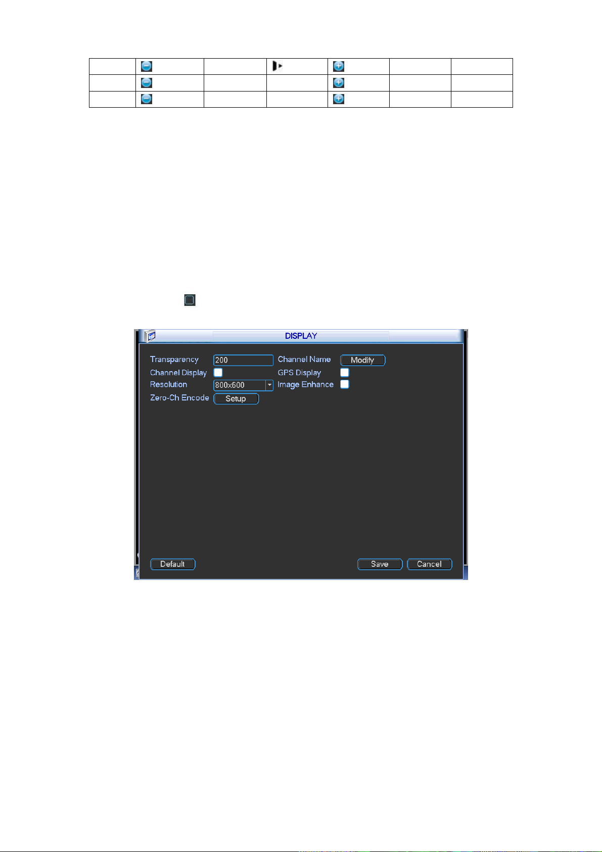
66
Zoom
Wide
Far
Focus
Near
│
Far
►│
Iris Close
Open
4.9.9 Display
Display setup interface is shown as below. See Figure 4-65.
Transparency: Here is for you to adjust transparency. The value ranges from 128 to 255.
Channel name: Here is for you to set camera channel name.
Time display: You can select to display time or not when system is playback.
Car number display: You can select to display plate number or not when system is playback.
GPS display: System displays GPS information in the screen for your reference. Please note
only the unit of GPS module supports this function.
Resolution: Please note system needs to reboot to active current setup.
Image enhance: Check the box; you can optimize the margin of the preview video.
Please highlight icon to select the corresponding function.
After completing all the setups please click save button, system goes back to the previous menu.
Figure 4-65
In Figure 4-65, click modify button after channel. You can see an interface shown as in Figure
4-66. Please note all your modification here applies to local end only. You need to refresh web or
client-end to get the latest channel name. System max support 25-digital character.
Page 75

67
Figure 4-66
Zero-Channel Encoding(Multiple-Preview): Click Setup button, you can go to the following
interface. See Figure 4-67. Here you can enable and set zero-channel encoding function so
that you can view several video sources at one channel.
Enable: This function is disabled by default. Check the box here to enable this function
so that you can control the zero-channel encoding function at the WEB.
Compression: System default setup is H.264. You can set according to device capability.
Resolution: System supports D1/HD1/CIF/2CIF/QCIF. The resolution value may vary
due to different device capabilities. Please select from the dropdown list.
Frame rate: System supports 1-25(30). The frame rate value may vary due to different
device capabilities. Please select from the dropdown list.
Bit Rate: System supports 640/768/896/1024. The bit rate value may vary due to
different device capabilities and frame rate setups. Please select from the dropdown list.
Save: Click the Save button to save current setup. If this function is disabled, you can not
operate zero-channel encoding function at the WEB, the video is black or null even you
operate when the function is disabled. After you enabled this function, login the Web and
you can select zero-channel encoding mode at the right corner of the
interface . Select a mode; you can view the local preview video.
4.9.10 Default
Figure 4-67
Page 76

68
Click default icon, system pops up a dialogue box. You can highlight to restore default factory
setup.
Select all
General
Encode
Schedule
RS232
Network
Alarm
Detect
PTZ
Display
Channel name
Please highlight icon to select the corresponding function. See Figure 4-68.
After all the setups please click OK button, system goes back to the previous menu.
Figure 4-68
Warning!
System menu color, language, video format, user account cannot restore default setup after
default operation!
4.10 Advanced
Double click advanced icon in the main window, the interface is shown as below. See Figure 4-69.
There are total five items: HDD, alarm output, record, account, and import/export.
Page 77

69
Figure 4-69
4.10.1 HDD Management
Here is for you to view and implement hard disk management. See Figure 4-70.
You can see current HDD type, status, capacity and record time. When HDD is working properly,
system is shown as O. When HDD error occurred, system is shown as X.
Alarm set: Click alarm set button, the interface is shown as below. See Figure 4-71. (This
interface is just like the abnormality setup). Please refer to chapter 4.8.6 for detailed
information.
HDD operation: You can select HDD mode from the dropdown list such as read-only or you
can erase all data in the HDD. Please note system needs to reboot to get all the modification
activated.
Figure 4-70
Page 78

70
4.10.2 Alarm Output
Here is for you to set proper alarm output.
Figure 4-71
Please highlight icon to select the corresponding alarm output.
After all the setups please click OK button, system goes back to the previous menu. See Figure
4-72.
Figure 4-72
4.10.3 Manual Record
Note:
You need to have proper rights to implement the following operations. Please make sure the
HDD has been properly installed.
4.10.3.1 Manual record menu
Right click mouse or in the main menu, Advanced->Manual Record.
Manual record menu is shown as in Figure 4-73.
4.10.3.2 Basic operation
There are two streams: main stream/extra stream. There are three statuses:
Page 79

71
schedule/manual/stop. Please highlight icon“○” to select corresponding channel.
Manual: The highest priority. After manual setup, all selected channels will begin ordinary
recording.
Schedule: Channel records as you have set in recording setup (Main
Menu->Setting->Schedule)
Stop: All channels stop recording.
Figure 4-73
4.10.3.3 Enable/disable record
Please check current channel status: “○” means it is not in recording status, “●” means it is in
recording status.
You can use mouse or direction key to highlight channel number. See Figure 4-74.
Figure 4-74
4.10.3.4 Enable all channel recording
Highlight ○ below All, you can enable all channel recording.
All channel schedule record
Please highlight “ALL” after “Schedule”. See Figure 4-75.
When system is in schedule recording, all channels will record as you have previously set
(Main menu->Setting->Schedule).
The corresponding indication light in front panel will turn on.
Page 80

72
Figure 4-75
All channel manual record
Please highlight “ALL” after “Manual.” See Figure 4-76.
When system is in manual recording, all scheduled set up you have set in will be null ((Main
menu->Setting->Schedule)).
You can see indication light in front panel turns on, system begins manual record now.
Figure 4-76
4.10.3.5 Stop all channel recording
Please highlight “ALL” after “Stop”. See Figure 4-77.
System stops all channel recording no matter what mode you have set in the menu (Main
menu->Setting->Schedule)
Figure 4-77
Page 81

73
4.10.4 Account
Here is for you to implement account management. See Figure 4-78. Here you can:
Add new user
Modify user
Add group
Modify group
Modify password.
For account management please note:
For the user account name and the user group, the string max length is 6-byte. The
backspace in front of or at the back of the string is invalid. There can be backspace in the
middle. The string includes the valid character, letter, number, underline, subtraction sign,
and dot.
System account adopts two-level management: group and user. No limit to group or user
amount.
For group or user management, there are two levels: admin and user.
The user name and group name can consist of eight bytes. One name can only be used once.
There are three default administrator users: admin/888888 and hidden user “default”.
Hidden user “default” is for system interior use only and can not be deleted. When there is no
login user, hidden user “default” automatically login. You can set some rights such as monitor
for this user so that you can view some channel view without login.
One user should belong to one group. User right can not exceed group right.
About reusable function: this function allows multiple users use the same account to login.
After all the setups please click save button, system goes back to the previous menu.
Figure 4-78
4.10.4.1 Modify Password
Click password button, the interface is shown as in Figure 4-79.
Here you can modify account password.
Please select the account from the dropdown list, input the old password and then input the new
password twice. Click the Save button to confirm current modification.
For the users of user account right, it can modify password of other users.
Page 82

74
Figure 4-79
4.10.4.2 Add/Modify Group
Click add group button, the interface is shown as below. See Figure 4-80.
Here you can input group name and then input some memo information if necessary.
There are total 40 rights such as control panel, shut down, real-time monitor, playback, record,
record file backup, PTZ, user account, system information view, alarm input/output setup, system
setup, log view, clear log, upgrade system, control device and etc.
The modify group interface is similar to the Figure 4-80.
Figure 4-80
4.10.4.3 Add/Modify User
Click add user button, the interface is shown as in Figure 4-81.
Please input the user name, password, select the group it belongs to from the dropdown list.
Then you can check the corresponding rights for current user.
For convenient user management, usually we recommend the general user right is lower than the
admin account.
The modify user interface is similar to Figure 4-81.
Page 83

75
Figure 4-81
4.10.5 Import/Export
The import/export interface is shown as below. See Figure 4-82.
This function allows you to copy current system configuration to other devices. It also supports
import, create new folder, and delete folder and etc function.
Figure 4-82
4.11 Backup
DVR supports USB burner, flash disk, portable HDD, eSATA HDD (Need external power
supplying and does not support hot swap). Here we introduce USB backup. You can refer to
Chapter 5 Web Operation for network download backup operation.
4.11.1 Detect Device
Page 84

76
Click backup button, you can see an interface is shown as in Figure 4-83. Here is for you to
view device information. You can view backup device name and its total space and free
space.
Figure 4-83
4.11.2 Backup
Select backup device and then set channel, file start time and end time.
Click add button, system begins search. All matched files are listed below. System
automatically calculates the capacity needed and remained. See Figure 4-84.
Figure 4-84
System only backup files with a √ before channel name. You can use AUX button to check or
cancel file.
Click backup button, you can backup selected files. There is a process bar for you reference.
See Figure 4-85. Click backup button, system begins burning. At the same time, the backup
button becomes stop button. You can view the remaining time and process bar at the left
bottom.
Page 85

77
Figure 4-85
When the system completes backup, you can see a dialogue box prompting successful
backup.
The file name format usually is: SN_CH+channel number+Time. In the file name, the YDM
format is Y+M+D+H+M+S. File extension name is .dav.
Tips:
During backup process, you can click ESC to exit current interface for other operation. The
system will not terminate backup process.
Note:
When you click stop button during the burning process, the stop function becomes activated
immediately. For example, if there are ten files, when you click stop system just backup five
files, system only save the previous 5 files in the device (But you can view ten file names).
4.12 Shutdown
Double click shutdown button, system pops up a dialogue box for you to select. See Figure 4-86.
Logout menu user: log out menu. You need to input password when you login the next time.
Restart application: reboot device.
Shutdown: system shuts down and turns off power.
Restart system: system begins rebooting.
Switch user: you can use another account to login.
If you shut down the device, there is a process bar for your reference, system waits for 3 seconds
and then shut down (You can not cancel).
Please note, sometimes you need to input the proper password to shut down the device.
Figure 4-86
Page 86

78
Input your IP
address here.
5 WEB OPERATION
There might be slightly difference in the interface due to different series.
5.1 Network Connection
Before web operation, please check the following items:
Network connection is right
DVR and PC network setup is right. Please refer to network setup(Setup ->Network)
Use order ping ***.***.***.***(* DVR default IP address is 192.168.1.108) to check connection
is OK or not. Usually the return TTL value should be less than 255.
Open the IE and then input DVR IP address.
System can automatically download latest web control and the new version can overwrite the
previous one.
If you want to un-install the web control, please run uninstall webrec3.0.bat. Or you can go to
C:\Program Files\webrec to remove single folder. Please note, before you un-install, please
close all web pages, otherwise the un-installation might result in error.
Current series product supports IE and Maxthon browser only.
5.2 Login
Open IE and input DVR address in the address column. For example, if your DVR IP is 10.10.3.16,
then please input http:// 10.10.3.16 in IE address column. See Figure 5-1.
Figure 5-1
System pops up warning information to ask you whether install webrec.cab control or not. Please
click yes button.
If you can’t download the ActiveX file, please modify your settings as follows. See Figure 5-2.
Page 87

79
Figure 5-2
After installation, the interface is shown as below. See Figure 5-3.
Please input your user name and password.
Default factory name is admin and password is admin.
Then you can select the login mode: LAN and WAN.
Note: For security reasons, please modify your password after you first login.
Figure 5-3
Page 88

80
5.3 LAN Mode
For the LAN mode, after you logged in, you can see the main window. See Figure 5-4.
Figure 5-4
This main window can be divided into the following sections.
Section 1: there are five function buttons: Live(chapter 5.4), setup (chapter 5.9), search
(chapter 5.10), alarm (chapter 5.11), and logout (chapter 5.12).
Section 2: There are channel number and one button: Start all. Start all button is to
enable/disable all-channel real-time monitor. Click it the button becomes yellow. See Figure
5-5.
Figure 5-5
Please refer to Figure 5-6 for main stream and extra stream switch information.
Figure 5-6
Section 3: Start dialogue button.
You can click this button to enable audio talk. Click 【▼】 to select bidirectional talk mode. There
are four options: DEFAULT, G711a, G711u and PCM. After you enable the bidirectional talk, the
Start talk button becomes End Talk button and it becomes yellow. See Figure 5-7.
Please note, the audio input port from the device to the client-end is using the first channel audio
Page 89

81
input port. During the bidirectional talk process, system will not encode the audio data from the
1-channel.
Figure 5-7
Section 4: Instant record button. Click it, the button becomes yellow and system begins
manual record. See Figure 5-8. Click it again, system restores previous record mode..
Figure 5-8
Section 5: Local play button.
The Web can playback the saved (Extension name is dav) files in the PC-end.
Click local play button, system pops up the following interface for you to select local play file. See
Figure 5-9.
Figure 5-9
Section 6: From the left to the right, you can see video quality/fluency/ full
screen/vertical-sync/1-window/4-window/6-window. You can set video fluency and real-time
feature priority.
Section 7: PTZ operation panel. Please refer to chapter 5.5 for detailed information.
Section 8: Image setup and alarm setup. Please refer to chapter 5.6 for detailed information.
Section 9: It is to display several channels at one window. Please refer to chapter 5.7 for
detailed information.
5.4 Real-time Monitor
In section 2, left click the channel name you want to view, you can see the corresponding video in
current window.
On the top left corner, you can view device IP(10.10.6.129), channel number(1), network monitor
bit stream(2466Kbps) and stream type (M=main stream. S=Sub stream). See Figure 5-10.
Page 90

82
Parameter
Function
Scan
Select Scan from the dropdown list.
Click Set button, you can set scan left and right limit.
Use direction buttons to move the camera to you desired location
and then click left limit button. Then move the camera again and
then click right limit button to set a right limit.
Preset
Select Preset from the dropdown list.
Turn the camera to the corresponding position and Input the
preset value. Click Add button to add a preset,.
1 2 3 4 5
1 2 3 4
Figure 5-10
On the top right corer, there are six unction buttons. See Figure 5-11.
Figure 5-11
1: Digital zoom: Click this button and then left drag the mouse in the zone to zoom in. right
click mouse system restores original status.
2: Local record. When you click local record button, the system begins recording and this
button becomes highlighted. You can go to system folder RecordDownload to view the
recorded file.
3: Snapshot picture. You can snapshoot important video. All images are memorized in system
client folder PictureDownload (default).
4: Audio :Turn on or off audio.(It has no relationship with system audio setup )
5: Close video.
5.5 PTZ
Before PTZ operation, please make sure you have properly set PTZ protocol. (Please refer to
chapter 5.9.5.7).
There are eight direction keys. In the middle of the eight direction keys, there is a 3D intelligent
positioning key.
Click 3D intelligent positioning key, system goes back to the single screen mode. Drag the mouse
in the screen to adjust section size. It can realize PTZ automatically.
Please refer to the following sheet for PTZ setup information.
Page 91

83
Parameter
Function
Tour
Select Tour from the dropdown list.
Input preset value in the column. Click Add preset button, you
have added one preset in the tour.
Repeat the above procedures you can add more presets in one
tour.
Or you can click delete preset button to remove one preset from
the tour.
Pattern
Select Pattern from the dropdown list.
You can input pattern value and then click Start button to begin
PTZ movement such as zoom, focus, iris, direction and etc. Then
you can click Add button to set one pattern.
Aux
Please input the corresponding aux value here.
You can select one option and then click AUX on or AUX off
button.
Light and
wiper
You can turn on or turn off the light/wiper.
You can click this icon to
display or hide the PTZ
control platform.
3D Intelligent Positioning
Key
Figure 5-12
5.6 Image/Relay-out
Select one monitor channel video and then click Image button in section 8, the interface is shown
as Figure 5-13.
5.6.1 Image
Here you can adjust its brightness, contrast, hue and saturation. (Current channel border
becomes green).
Or you can click Reset button to restore system default setup.
Page 92

84
Figure 5-13
5.6.2 Relay output
Here you can select alarm output channel, the select channel alarm mode becomes manual and
alarm is enabled. See Figure 5-14. It is corresponding to the alarm output 1 (A1) and alarm output
2 (A2) of the rear panel.
Figure 5-14
5.7 Zero-channel encoding
System allows you to preview several channels on one channel. It supports 1/4-window. See
Figure 5-15.
Please note only the product of this icon can support current function.
Figure 5-15
5.8 WAN Login
In WAN mode, after you logged in, the interface is shown as below. See Figure 5-16.
Page 93

85
Figure 5-16
Please refer to the following contents for LAN and WAN login difference.
1) In the WAN mode, system opens the main stream of the first channel to monitor by default. The
open/close button on the left pane is null.
2) You can select different channel and different monitor mode at the bottom of the interface.
3) Multiple-channel monitor, system adopts extra stream to monitor by default. Double click one
channel, system switches to single channel and system uses main stream to monitor. You can
view there are two icons at the left top corner of the channel number for you reference. M stands
for main stream. S stands for sub stream (extra stream).
4) If you login via the WAN mode, system does not support alarm activation to open the video
function in the Alarm setup interface.
Important
For multiple-channel monitor mode, system adopts extra stream to monitor by default. You
can not modify manually. All channels are trying to synchronize. Please note the
synchronization effect still depends on your network environments.
For bandwidth consideration, system can not support monitor and playback at the same time.
System auto closes monitor or playback interface when you are searching setup in the
configuration interface. It is to enhance search speed.
5.9 Setup
5.9.1 Channel
5.9.1.1 Conditions Here you can view device property information. The setups become valid immediately after you set. See Figure 5-17.
Page 94

86
Parameter
Function
Channel
Please select a channel from the dropdown list.
Period
It divides one day (24 hours) to two periods. You can set
different hue, brightness, and contrast for different periods.
Hue
It is to adjust monitor video brightness and darkness level. The
default value is 50.
The bigger the value is, the large the contrast between the bright
and dark section is and vice versa.
Brightness
It is to adjust monitor window brightness. The default value is 50.
The larger the number is , the bright the video is. When you
input the value here, the bright section and the dark section of
the video will be adjusted accordingly. You can use this
function when the whole video is too dark or too bright. Please
note the video may become hazy if the value is too high. The
value ranges from 0 to 100.The recommended value ranges
from 40 to 60.
Contrast
It is to adjust monitor window contrast. The value ranges from 0
to 100. The default value is 50.
The larger the number is, the higher the contrast is. You can use
this function when the whole video bright is OK but the contrast
is not proper. Please note the video may become hazy if the
value is too low. If this value is too high, the dark section may
lack brightness while the bright section may over exposure .The
recommended value ranges from 40 to 60.
Saturation
It is to adjust monitor window saturation. The value ranges from
0 to 100. The default value is 50.
The larger the number is, the strong the color is. This value has
no effect on the general brightness of the whole video. The
video color may become too strong if the value is too high. For
the grey part of the video, the distortion may occur if the white
balance is not accurate. Please note the video may not be
Figure 5-17
Please refer to the following sheet for detailed information.
Page 95
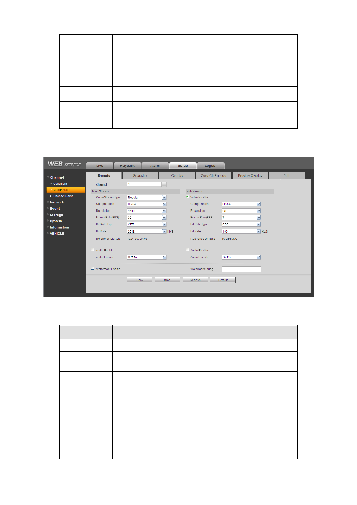
87
attractive if the value is too low. The recommended value ranges
from 40 to 60.
Gain
The gain adjust is to set the gain value. The smaller the value is,
the low the noise is. But the brightness is also too low in the dark
environments. It can enhance the video brightness if the value is
high. But the video noise may become too clear.
White level
It is to enhance video effect.
Color mode
It includes several modes such as standard, color. You can
select corresponding color mode here, you can see hue,
brightness, and contrast and etc will adjust accordingly.
Parameter
Function
Channel
Please select a channel from the dropdown list.
Video enable
Check the box here to enable extra stream video. This item is
enabled by default.
Code stream
type
It includes main stream, motion stream and alarm stream. You
can select different encode frame rates form different recorded
events.
System supports active control frame function (ACF). It allows
you to record in different frame rates.
For example, you can use high frame rate to record important
events, record scheduled event in lower frame rate and it allows
you to set different frame rates for alarm record.
Compression
The main bit stream supports H.264. The extra stream supports
H.264, MJPG.
5.9.1.2 Video and Audio
5.9.1.2.1 Encode The encode interface is shown as below. See Figure 5-18.
Figure 5-18
Please refer to the following sheet for detailed information.
Page 96

88
Resolution
System supports various resolutions, you can select from the
dropdown list. The main stream supports
960H/D1/HD1/CIF/2CIF/QCIF and the extra stream supports
D1/CIF/QCIF. Please note the option may vary due to different
series.
Frame Rate
PAL:1~25f/s;NTSC:1~30f/s.
Bit Rate
Main stream: You can set bit rate here to change video
quality. The large the bit rate is , the better the quality is.
Please refer to recommend bit rate for the detailed
information.
Extra stream: In CBR, the bit rate here is the max value.
In dynamic video, system needs to low frame rate or
video quality to guarantee the value. The value is null in
VBR mode.
Reference bit
rate
Recommended bit rate value according to the resolution and
frame rate you have set.
Audio enable
System supports G711a/PCM/G711μ.
Watermark
enable
This function allows you to verify the video is tampered or not.
Here you can select watermark bit stream, watermark mode and
watermark character. Default character is DigitalCCTV. The max
length is 85-digit. The character can only include number,
character and underline.
Parameter
Function
Snapshot type
There are two modes: Timing (schedule) and Event (activation).
Timing snapshot is valid during the specified period you set.
Activation snapshot only is valid when tampering alarm or
5.9.1.2.2 Snapshot The snapshot interface is shown as in Figure 5-19.
Figure 5-19
Please refer to the following sheet for detailed information.
Page 97

89
local activation alarm occurs.
Image size
It is the same with the resolution of the main stream.
Quality
It is to set the image quality. There are six levels.
Interval
It is to set snapshot frequency.
Copy
Click it; you can copy current channel setup to other channel(s).
Parameter
Function
Cover-area
(Privacy mask)
Check Preview or Monitor first.
Click Set button, you can privacy mask the specified video in the
preview or monitor video.
System max supports 4 privacy mask zones.
Time Title
You can enable this function so that system overlays time
information in video window.
You can use the mouse to drag the time title position.
You can view time title on the live video of the WEB or the
playback video.
Channel Title
You can enable this function so that system overlays channel
information in video window.
You can use the mouse to drag the channel title position.
You can view channel title on the live video of the WEB or the
playback video.
GPS Overlay
Overlay GPS information such as (speed, longitude, latitude) on
the video.
5.9.1.2.3 Overlay The video overlay interface is shown as in Figure 5-20.
Figure 5-20
Please refer to the following sheet for detailed information.
Page 98

90
Plate Overlay
Overlay some plate information on the video.
Parameter
Function
Compression
H.264
Resolution
D1/HD1/CIF/2CIF/QCIF.
Frame Rate
1~25(30).
Bit Rate(kb/s)
640/768/896/1024.
5.9.1.2.4 Zero-Ch Encoding The zero-channel encoding interface is shown as in Figure 5-21.
Figure 5-21
Please refer to the following sheet for detailed information.
5.9.1.2.5 Preview Overlay The preview overlay interface is shown as in Figure 5-22. You can overlay time, speed, plate information and etc on the device preview interface and Web monitor video.
The preview overlay is to overlay information on the preview interface or WEB monitor
video, the information is not included in record file.
Figure 5-22
Page 99
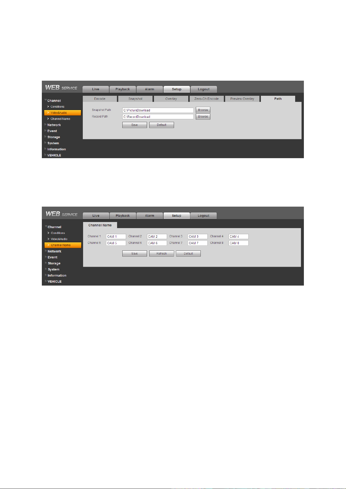
91
5.9.1.2.6 Path The storage path interface is shown as in Figure 5-23. Here you can set snap image saved path and the record storage path. The default setup is C:\PictureDownload and C:\RecordDownload. Please click the Save button to save current setup.
Figure 5-23
5.9.1.3 Channel Name Here you can set channel name. See Figure 5-24.
Figure 5-24
5.9.2 Network
5.9.2.1 TCP/IP The TCP/IP interface is shown as in Figure 5-25.
Page 100

92
Parameter
Function
Mode
There are two modes: static mode and the DHCP mode.
The IP/submask/gateway are null when you select the
DHCP mode to auto search the IP.
If you select the static mode, you need to set the
IP/submask/gateway manually.
If you select the DHCP mode, you can view the
IP/submask/gateway from the DHCP.
If you switch from the DHCP mode to the static mode, you
need to reset the IP parameters.
Mac Address
It is to display host Mac address.
MTU
Max transmission unit.
IP Version
It is to select IP version. IPV4 or IPV6.
You can access the IP address of these two versions.
IP Address
Please use the keyboard to input the corresponding number to
modify the IP address and then set the corresponding subnet
mask and the default gateway.
Subnet Mask
Input subnet mask according to your device IP.
Default Gateway
Input default gateway according to your device IP.
Preferred DNS
DNS IP address.
Alternate DNS
Alternate DNS IP address.
For the IP address of IPv6 version, default gateway, preferred DNS and
alternate DNS, the input value shall be 128-digit. It shall not be left in blank.
LAN load
System can process the downloaded data first if you enable this
function. The download speed is 1.5X or 2.0X of the normal
speed.
Figure 5-25
Please refer to the following sheet for detailed information.
 Loading...