

Page 1
INSTRUCTION MANUAL
Page 2

Page 3

TABLE OF CONTENTS
Features and Specifications
a. Overview 1
b. Features 2
c. IC720 App 2
d. Specifications 3-4
e. Dimensions 5
Camera Installation
a. Ceiling Installation 6-8
b. Corner/Pole Mount 9-11
Web GUI | IC720 Management
a. Network Connection 12
b. Logging In, and Main Interface 13-14
c. Connecting IC720 to an NVR 15-16
Appendices
a. Toxic or Hazardous Elements 17
Page 4

IC REALTIME
1 | FEATURES AND SPECIFICATIONS
Page 5
This section outlines the primary features of the IC Realtime IC720
Camera. It also outlines basic Architectural and Engineering
specifications.
1a. OVERVIEW
This IC Realtime series produc t is an excellent situational awareness
IP Camera – the camera designed to see everything with no blind
spots. It adopts a dual lens design, and is powered by a robust
Qualcomm, Snapdragon 800 series processor, enabling it to maintain
reliable, 24/7 operation. Utilizing both H.264 video compression
and AAC audio compression technology enables the highest quality
of recorded audio/video, while maintaining the lowest bitrate
utilization.
The IC720 series camera is an HD, dual lens 12 MegaPixel IP Camera
with an integrated microphone. The dual lens design of the camera
allows for video capture in a full 360 degree vertical and 360 degree
horizontal format. This camera is fully suited for full operation as a
standalone device.
The 12MP recording resolution and extreme wide angle lens design
makes this IPC well equipped for installation in various institutions
ranging from residential, commercial, governmental , and enterprise
environments.
1
Page 6

IC REALTIME
1b. FEATURES
IC Realtime IC720 series IP Cameras all support the following features:
HD, 360 x 360 Video Monitoring: This IP Camera uses two SONY
IMX172 (12MP) sensors.
SD Card Storage: As a standalone device, the IPC can hold a 32GB
micro SD card suitable for storing video direct from the camera.
1c. IC720 APP
Network Operation: Full system control (including live view,
playback, backup,VPTZ control, and system conf iguration) is available
Secure Archiving: Audio Video data is compressed and packaged
into a secure, and watermarked video format. This bolsters archived
with over the network. Client software is available for both Mac and
PC systems.
video integr i t y, and prevents vicious dat a manipulation. Video is
also watermarked with special data for evidentiary purposes.
VPTZ Control: This IPC includes a special dewarping algorithm,
enabling users to ‘Virtually’ Pan/Tilt/Zoom across a high resolution
Compression Format: H.264 video and AAC audio enables high
quality video recording while maint aining the lowes t file sizes
image, in order to get the highest visibility and situational awareness
from the camera.
possible.
2
Page 7
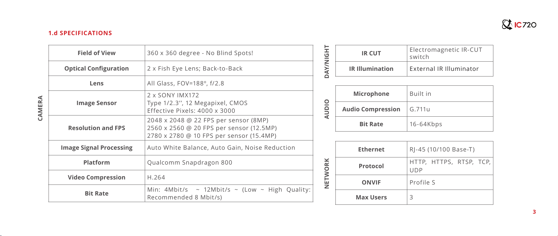
Field of View 360 x 360 degree - No Blind Spots!
Optical Conguration 2 x Fish Eye Lens; Back-to-Back
Lens All Glass, FOV=188º, f/2.8
Image Sensor
2 x SONY IMX172
Type 1/2.3’ ’, 12 Megapixel, CMOS
Effective Pixels: 4000 x 3000
Resolution and FPS
2048 x 2048 @ 22 FPS per sensor (8MP)
2560 x 2560 @ 20 FPS per sensor (12.5MP)
2780 x 2780 @ 10 FPS per sensor (15.4MP)
Image Signal Processing Auto White Balance, Auto Gain, Noise Reduction
Platform Qualcomm Snapdragon 800
Video Compression H.264
Bit Rate
Min: 4Mbit/s ~ 12Mbit/s ~ (Low ~ High Quality:
Recommended 8 Mbit/s)
IR CUT
Electromagnetic IR-CUT
switch
IR Illumination External IR Illuminator
Microphone Built in
Audio Compression G.711u
Bit Rate 16-6 4Kbps
Ethernet RJ-45 (10/100 Base-T)
Protocol
HTTP, HTTPS, RTSP, TCP,
UDP
ONVIF Profile S
Max Users 3
1.d SPECIFICATIONS
CAMERA
DAY/NIGHTAUDIONETWORK
3
Page 8

IC REALTIME
1.d SPECIFICATIONS (Continued)
NVR IC Realtime NVR-8128; NVR-8256
STORAGEPOWEROTHER
Memory Slot Micro SD (up to 32GB
Power Supply 12VDC, PoE
Power Consumption ~8 Watts
Mount Wall, Ceiling, Corner, Pole
Size 4.2’’ x 11.7’’ x 2.9’’ (108mm x 293mm x 73mm)
Weight ~3 lbs
Protection For Indoor use only
Working environment 40-95 degrees F / 10-35 degrees C; 10%-80%
4
Page 9

The ‘front’ of the IC720 Camera. Ceiling mount orientation.
1.e DIMENSIONAL VIEWS
Bottom view of the IC720 Camera. The cable harness extends out of the center.
5
Page 10

IC REALTIME
2 | CAMERA INSTALLATION
Page 11

The IC720 in a Ceiling mount configuration.
2.a CEILING INSTALLATION: STEP BY STEP
This section outlines the proper way to mount and install an
IC720 series IP Camera. Suitable methods of installing the
IPC include either Ceiling ins tallation, Corner ins tallation, or
Pole Installation. Note that hardware including screws and
anchors are included for the camera installation.
6
Page 12

IC REALTIME
The Beauty shroud simply slides over the camera body to provide a
sleek installation t and feel.
The Beauty shroud simply slides over the camera body to provide a
sleek installation t and feel.
Step 1: Install the Beauty Shroud
Slide the shroud over the IC720 Camera body from the top.
Step 2: Install the Interface Plate
At tach the inter face plate w ith (4) #10 -24 Pan Head screws
and locking washers. Tighten to secure the inter face plate
to the camera body.
7
Page 13

The full camera assembly, prior to permanent installation. (3) M3
Cap Screws x the camera assembly to the ceiling mount.
Ethernet cable being plugged into modem, routher, or switch board.
Step 3: Connect Wiring
Pass cables the cables through the pole mount and then connect
your Ethernet and power cables (if not using Power Over
Ethernet). Once physical cable connections are established, the
camera can be permanently affixed to the interface plate.
Step 4: Secure the Camera Assembly to the Ceiling Mount
Secure the assembly to the ceiling mount itself with (3) M3
Cap screws.
8
Page 14

IC REALTIME
2.b CORNER/POLE MOUNT: STEP BY STEP
This section outlines the proper way to mount and install an IC720
series IP Camera. Sui table methods of insta lling the IPC include eit her
Ceiling installation, Corner installation, or Pole Installation. Note that
hardware including screws and anchors are included for the camera
installation.
The IC720 Beam in a Pole Mount installation.
9
Page 15

The Beauty shroud simply slides over the camera body to provide a
sleek installation t and feel.
Attaching the interface plate to the camera body.
Note: Install the beauty shroud prior to this step!
Step 1: Install the Beauty Shroud
Slide the shroud over the IC720 Camera body from the top.
Step 2: Install the Interface Plate
At tach the inter face plate w ith (4) #10 -24 Pan Head screws
and locking washers. Tighten to secure the inter face plate
to the camera body.
10
Page 16

IC REALTIME
The full camera assembly, prior to permanent installation. (4) M8
Cap Screws x the camera assembly to the pole mount.
Step 4: Secure the Camera Assembly to the Pole Mount
Secure the assembly to the ceiling mount itself with (4) M8
Pan Head screws.
Step 3: Connect Wiring
Connect your Ethernet and power cables (if not using Power Over
Ethernet). Once physic al cable connections are established, the
camera can be permanently affixed to the interface plate.
11
Ethernet cable being plugged into modem, routher, or switch board.
Page 17

3 | WEB GUI | IC720 MANAGEMENT
Page 18

IC REALTIME
This section outlines how to assign an IP address to the camera, and
how to access and configure the IC720 Beam via it’s built in Web
Interface. The Web Interface is used primarily to configure the camera
parameters initially. The IC720 application is the desired client
software to use with when viewing the IC720 Beam series camera.
Step 2: Assign an IP address to the IP Camera.
The IC720 Beam Series camera (and all ICR IP Cameras) are designed
to automatically assign an IP address from the router on your local
area network (via DHCP).
12
3a. NETWORK CONNECTION
IC Realtime IC720 Beam series IP Cameras all support the following
features:
Step 1: Ensure the Camera is physically connected to your
Network, and Powered ON.
Patch the IP Camera into your network with a st andard Ethernet
cable. Provide the camera with power either via PoE or wi th the
separate 12VDC power input jack.
You can use our IP Auto Search utilit y to rapidly find and change IP
addresses for IC720 Beam series IP Cameras. The utility is available
on our support page at :
http://www.icrealtime.com/support/software-downloads
Page 19

3.b LOGGING IN, AND MAIN INTERFACE
Step 1: Open up your Web Browser (Safari, Chrome, Firefox, or
IE) and input the IP address of your IP camera.
In Example, open Safari and browse to http://192.168.1.108
Step 2: Login to the camera with the default credentials
By default, the username is ‘admin’ and the password is ‘admin’. It is
always strongly recommended to change the default passwords after
the initial setup. The cameras login page should appea as shown.
13
Page 20

IC REALTIME
Step 3: Change setup parameters as needed
Once logged into the Web Interface, you will be presented with 5
options from the Menu Tree on the left side:
Camera Menu allows you to change Resolution, FrameRate, and
BitRate parameters.
Network Menu allows you to assign an IP address , as well as change
the default port settings.
System Menu allows for configuration of the Date/Time, Language,
as well as the IC720 Beam camera device logs.
Accounts Menu allows you to manage accounts (Add/Delete/
Modify), change passwords, and create different Roles.
Information Menu provides Version information, as well as
Firmware Updates for the IC720 Beam series camera.
14
Page 21

3.c Connecting IC720 to an NVR
IC720 utilizes the industry standard ONVIF protocol, so connecting
to an NVR should be a breeze. Each image of the camera (2 total)
has an independent ONVIF port number for connection. Here’s an
example of pairing the IC720 device to an ICRealtime NVR.
Step 1: Login to the ICRealtime NVR series device, and navigate
to the ‘Remote Devices’ menu.
Step 2: Hit ‘Device Search’ on this page to scan your LAN for any
IC720 series cameras.
15
Page 22

IC REALTIME
Step 3: Double click on the IP Address of your IC720 from the
‘Device Search’ menu to add the first IC720 sensor.
This will automatically add this to your NV R, withou t needing to input
any additional information.
Step 4: Double click on the same IP Address again, if you want to
add the second sensor (you will need to change the port number
in the table below).
Again, this will automatically add the Firs t sensor connection info
to your NVR. Simply select this newly added Remote Device, click
Modify, and change the Port Number from 8070 to 8071, and Save.
This will pair the NVR to the second sensor!
16
Page 23

4 | APPENDIX: TOXIC AND HAZARDOUS
MATERIALS REPORT
Page 24

IC REALTIME
17
Component Name
Circuit Board Component
Device Case
Wire and Cable
Packaging Components
Video Compression
Bit Rate
Tox i c o r H a z ard o u s Mater i a l s o r El e m ent s
Pb Hg Cd Cr VI PBB PBDE
Note
This user manual is intended for reference only. Slight
dif ferences may be found in the user interface as
products continually develop.
All designs and sof tware herein are subjec t to change
without prior written consent.
All trademarks and registered trademarks mentioned
are the properties of their respective owners.
Please visit http://www.icrealtime.com for more
information.
Page 25

Page 26

© 2015 IC Realtime, LLC.
3050 N Andrews Ave Ext
Pompano Beach, FL 33064
Phone 866.997.9009 • Fax 866.860.3860
 Loading...