

Page 1

ICRealtime Network Video Recorder
User’s Manual
V 3.1.0
Page 2

Table of Contents
1 Features and Specifications ...............................................................................................................1
1.1 Overview........................................................................................................................................1
1.2 Features.........................................................................................................................................1
1.3 Specifications................................................................................................................................2
1.3.1 NVR4i/NVR8i/ NVR4i-P/NVR8i-P Series...........................................................................2
1.3.2 NVR708S2-P/NVR716S2-P/NVR732S2-P Series ...........................................................3
1.3.3 NVR708X2/NVR716X2/NVR732X2 Series .......................................................................5
2 Front Panel and Rear Panel ...............................................................................................................8
2.1 Front Panel....................................................................................................................................8
2.1.1 NVR4i/NVR8i/ NVR4i-P/NVR8i-P Series...........................................................................8
2.1.2 NVR708S2-P/NVR716S2-P/NVR732S2-P Series ...........................................................8
2.1.3 NVR708X2/NVR716X2/NVR732X2 Series .....................................................................10
2.2 Rear Panel ..................................................................................................................................13
2.2.1 NVR4i/NVR8i/ NVR4i-P/NVR8i-P Series.........................................................................13
2.2.2 NVR708S2-P/NVR716S2-P/NVR732S2-P Series .........................................................14
2.2.3 NVR708X2/NVR716X2/NVR732X2 Series .....................................................................16
2.3 Alarm Connection.......................................................................................................................17
2.4 Bidirectional talk .........................................................................................................................18
2.4.1 Device-end to PC-end ........................................................................................................18
2.4.2 PC-end to the device-end ..................................................................................................18
2.5 Mouse Operation........................................................................................................................19
3 HDD Installation..................................................................................................................................21
3.1 NVR4i/NVR8i/NVR4i-P/NVR8i-P Series.................................................................................21
3.2 NVR708S2-P/ NVR716S2-P/ NVR732S2-P Series ..............................................................21
3.3 NVR708X2/ NVR716X2/ NVR732X2 Series ..........................................................................22
4
GUI Operation.....................................................................................................................................24
4.1 Login.............................................................................................................................................24
i
Page 3

4.2 Right Click Menu ........................................................................................................................26
4.3 Main Menu...................................................................................................................................27
4.4 Search & Playback.....................................................................................................................27
4.5 Information ..................................................................................................................................31
4.5.1 HDD Information..................................................................................................................32
4.5.2 BPS........................................................................................................................................33
4.5.3 Log.........................................................................................................................................34
4.5.4 Version ..................................................................................................................................35
4.5.5 Online Users.........................................................................................................................35
4.5.6 Remote Device Information ...............................................................................................35
4.5.7 Network Info .........................................................................................................................36
4.5.7.1 Network Test................................................................................................................36
4.5.7.2 Network Load..............................................................................................................37
4.6 Setting..........................................................................................................................................38
4.6.1 General .................................................................................................................................38
4.6.2 Encode ..................................................................................................................................41
4.6.3 Schedule...............................................................................................................................43
4.6.3.1 Quick Setup.................................................................................................................44
4.6.4 RS232 ...................................................................................................................................44
4.6.5 Network.................................................................................................................................45
4.6.5.1 Network Setting ..........................................................................................................46
4.6.5.2 IP Filter.........................................................................................................................47
4.6.5.3 NTP Setup...................................................................................................................48
4.6.5.4 Multicast.......................................................................................................................49
4.6.5.5 PPPoE
4.6.5.6 DDNS ...........................................................................................................................50
4.6.5.7 UPNP ...........................................................................................................................52
4.6.5.8 WIFI Setting.................................................................................................................53
4.6.5.9 Email ............................................................................................................................55
4.6.5.10 FTP...............................................................................................................................56
4.6.5.11 Alarm center................................................................................................................58
4.6.5.12 SNMP...........................................................................................................................58
4.6.5.13 Auto register................................................................................................................59
4.6.6 Alarm .....................................................................................................................................60
4.6.7 Detect ....................................................................................................................................63
4.6.7.1 Motion Detect..............................................................................................................64
4.6.7.2 Video Loss...................................................................................................................66
4.6.7.3 Camera Masking ........................................................................................................66
4.6.8 PTZ ........................................................................................................................................67
4.6.9 Display ..................................................................................................................................69
4.6.10 Default...................................................................................................................................70
..........................................................................................................................50
ii
Page 4

4.6.11 Remote Device ....................................................................................................................71
4.6.11.1 UPNP ...........................................................................................................................71
4.6.11.2 Built-in Switch Setup ..................................................................................................71
4.6.11.3 Remote Device ...........................................................................................................71
4.6.11.4 Short-cut Menu ...........................................................................................................74
4.7 Advanced.....................................................................................................................................75
4.7.1 HDD Management...............................................................................................................76
4.7.2 Abnormality...........................................................................................................................78
4.7.3 Alarm Output ........................................................................................................................79
4.7.4 Manual Record.....................................................................................................................79
4.7.4.1 Manual record menu..................................................................................................80
4.7.4.2 Basic operation ...........................................................................................................80
4.7.4.3 Enable/disable record ................................................................................................80
4.7.4.4 Enable all channel recording ....................................................................................80
4.7.4.5 Stop all channel recording.........................................................................................81
4.7.5 Account .................................................................................................................................82
4.7.5.1 Modify Password ........................................................................................................83
4.7.5.2 Add/Modify Group ......................................................................................................83
4.7.5.3 Add/Modify User .........................................................................................................84
4.7.6 Auto Maintenance ...............................................................................................................84
4.7.7 Config Backup......................................................................................................................85
4.8 Shutdown.....................................................................................................................................85
5 Quick Configuration Tool...................................................................................................................87
5.1 Overview......................................................................................................................................87
5.2 Operation.....................................................................................................................................87
6
Web Operation....................................................................................................................................90
6.1 General Introduction ..................................................................................................................90
6.1.1 Preparation ...........................................................................................................................90
6.1.2 Log in.....................................................................................................................................91
6.2 LAN Mode....................................................................................................................................92
6.2.1 Monitor Channel Menu Tree ..............................................................................................93
6.2.2 System Menu .......................................................................................................................96
6.2.3 Monitor Window Switch ......................................................................................................96
6.2.4 PTZ Control ..........................................................................................................................96
6.2.5 Color and More Setup.........................................................................................................98
6.3 WAN Login ..................................................................................................................................99
iii
Page 5

6.4 Configuration.............................................................................................................................10 1
6.4.1 System Information ...........................................................................................................101
6.4.1.1 Version Information..................................................................................................101
6.4.1.2 HDD information .......................................................................................................102
6.4.1.3 Log..............................................................................................................................102
6.4.2 System Configuration .......................................................................................................103
6.4.2.1 General Setup...........................................................................................................103
6.4.2.2 Encode.......................................................................................................................105
6.4.2.3 Schedule....................................................................................................................106
6.4.2.4 RS232 ........................................................................................................................108
6.4.2.5 Network......................................................................................................................109
6.4.2.6 Alarm ..........................................................................................................................117
6.4.2.1 Detect.........................................................................................................................119
6.4.2.2 PTZ.............................................................................................................................121
6.4.2.3 Default & Backup......................................................................................................122
6.4.3 Advanced............................................................................................................................123
6.4.3.1 HDD Management ...................................................................................................123
6.4.3.2 Abnormity...................................................................................................................124
6.4.3.3 Alarm I/O....................................................................................................................125
6.4.3.4 Record........................................................................................................................126
6.4.3.5 Account ......................................................................................................................126
6.4.3.6 Snapshot....................................................................................................................128
6.4.3.7 Auto Maintenance ....................................................................................................128
6.4.3.8 Remote device..........................................................................................................129
6.4.3.9
6.4.4 Additional Function............................................................................................................131
6.4.4.1 IPC Config .................................................................................................................131
6.4.4.2 Auto register..............................................................................................................133
6.4.4.3 Mobile Config ............................................................................................................133
6.4.4.4 WIFI Config ...............................................................................................................134
Preview Control.............................................................................................................130
6.5 Search........................................................................................................................................135
6.6 Alarm..........................................................................................................................................138
6.7 About..........................................................................................................................................140
6.8 Log out .......................................................................................................................................140
7 FAQ ....................................................................................................................................................141
8 Appendix A HDD Capacity Calculation.........................................................................................146
9 Appendix B Compatible SATA HDD .............................................................................................147
iv
Page 6

10 Appendix C Compatible USB2.0 List ........................................................................................152
11 Appendix D Compatible Displayer List......................................................................................154
Appendix H Toxic or Hazardous Materials or Elements.....................................................................155
v
Page 7

Welcome
Thank you for purchasing our network video recorder!
This user’s manual is designed to be a reference tool for your system.
Please open the accessory bag to check the items one by one in accordance with the list below.
Contact your local retailer ASAP if something is missing or damaged in the bag.
vi
Page 8

Important Safeguards and Warnings
1.Electrical safety
All installation and operation here should conform to your local electrical safety codes.
We assume no liability or responsibility for all the fires or electrical shock caused by improper
handling or installation.
2.Transportation security
Heavy stress, violent vibration or water splash are not allowed during transportation, storage and
installation.
3.Installation
Keep upwards. Handle with care.
Do not apply power to the NVR before completing installation.
Do not place objects on the NVR
4.Qualified engineers needed
All the examination and repair work should be done by the qualified service engineers.
We are not liable for any problems caused by unauthorized modifications or attempted repair.
5.Environment
The NVR should be installed in a cool, dry place away from direct sunlight, inflammable, explosive
substances and etc.
This series product shall be transported, storage and used in the specified environments.
6. Accessories
Be sure to use all the accessories recommended by manufacturer.
Before installation, please open the package and check all the components are included.
Contact your local retailer ASAP if something is broken in your package.
7. Lithium battery
Improper battery use may result in fire, explosion, or personal injury!
When replace the battery, please make sure you are using the same model!
Before your operation please read the following instructions carefully.
z Installation environment
Keep away from extreme hot places and sources;
Avoid direct sunlight;
Keep away from extreme humid places;
Avoid violent vibration;
Do not put other devices on the top of the NVR;
Be installed in well ventilated place; do not block the vent.
z Accessories
vii
Page 9

Check the following accessories after opening the box:
z Please refer to the packing list in the box *
viii
Page 10

1 Features and Specifications
1.1 Overview
This series NVR is a high performance network video recorder. This series product support local
preview, multiple-window display, recorded file local storage, remote control and mouse shortcut
menu operation, and remote management and control function.
This series product supports centre storage, front-end storage and client-end storage. The
monitor zone in the front-end can be set in anywhere. Working with other front-end devices such
as IPC, NVS, this series product can establish a strong surveillance network via the CMS. In the
network system, there is only one network cable from the monitor centre to the monitor zone in
the whole network. There is no audio/video cable from the monitor centre to the monitor zone. The
whole project is featuring of simple connection, low-cost, low maintenance work.
This series NVR can be widely used in many areas such as public security, water conservancy,
transportation and education.
1.2 Features
User
Management
Storage
Alarm
Network
Monitor
Window Split
Record
• Each group has different management powers that can be edited freely.
Every user belongs to an exclusive group.
• Via corresponding setup (such as alarm setup and schedule setup), you
can backup related audio/video data in the network video recorder.
• Support Web record and record local video and storage the file in the
client end.
• Respond to external alarm simultaneously (within 200MS), based on
user’s pre-defined relay setup, system can process the alarm input
correctly and prompt user by screen and voice (support pre-recorded
audio).
• Support central alarm server setup, so that alarm information can
remotely notify user automatically. Alarm input can be derived from
various connected peripheral devices.
• Alert you via EMAIL.
• Through network, sending audio/video data compressed by IPC or NVS
to client-ends, then the data will be decompressed and display. If
bandwidth is big enough, latency is less than 500ms
• Support max 10 connections
• Transmit audio/video data by HTTP, TCP, UDP, MULTICAST,
RTP/RTCP and etc.
• Transmit some alarm data or alarm info by SMTP.
• Support WEB access in WAN.
• Adopt the video compression and digital process to show several
windows in one monitor. Support 1/4/8/9/16-window display.
• Support schedule record function. Save the recorded files in the HDD,
client-end PC, or network storage server. You can search or playback
the saved files at the local-end or via the Web.
1
Page 11

• Support network backup, USB2.0 record backup function, the recorded
Backup
Network
Management
Peripheral
Equipment
Management
Auxiliary
files can be saved in network storage server, peripheral USB2.0
device, burner and etc.
• Supervise NVR configuration and control power via Ethernet.
• Support management via WEB.
• Support peripheral equipment management such as protocol setup and
port connection.
• Support transparent data transmission such as RS232 (RS-422), RS485
(RS-485).
• Support switch between NTSC and PAL.
• Support real-time system resources information and running statistics
display.
• Support log file.
• Local GUI output. Shortcut menu operation via mouse.
• IR control function. Shortcut menu operation via remote control.
• Support IPC or NVS remote video preview and control.
1.3 Specifications
1.3.1 NVR4i/NVR8i/ NVR4i-P/NVR8i-P Series
Parameter
Specifications
NVR4i/NVR8i NVR4i-P/NVR8i-P
System
Resources
Operation
System
Operation
Interface
Video
Compression
Encode
Capacity
Audio
Compression
Video Output
Max support 16-ch standard definition with the transmission rate of 2Mbps for each
channel;
8-channel 720P, with the transmission rate of 4Mbps for each channel;
4-channel 1080P, with the transmission rate of 8Mbps for each channel;
Support 20 online users at the same time,
The image delay time of each channel is under 500ms.
Embedded Linux real-time operation system
WEB/Local GUI
H.264/MPEG4
For H.264, it max supports 16-channel D1, 8-channel 720P, 4-channel 1080P.
G.711a
1-channel VGA analog video output.
Video Input
HDMI
Audio Input
Audio Output
4/8/16-ch network compression video input
1-ch HDMI output.
1-ch bidirectional audio input
N/A
2
Page 12

Wireless AP
antenna
N/A
Window Split
Multiple-chann
el Playback
Alarm Input
Alarm Output
Storage
RS232 Port
RS485 port
USB2.0 Port
Network
Connection
Power Port
Power Button
1/4/9-window
Max 16-channel D1/8-channel 720P/4-channel 1080P playback.
N/A
N/A
One built-in SATA port.
N/A
N/A
One peripheral USB2.0 port.
One RJ45 10/100Mbps self-adaptive Ethernet port.
One power port, power adapter. Input DC
12V.
No on/off button. Connect to the power cable to boot up.
Two power ports, power adapter. Input DC
12V or DC 48V.
Power Button
IR Remote
Control
Receiver
Clock
Indication Light
Power
Consumption
Working
Temperature
Working
Humidity
Air pressure
Dimension
Weight
Installation
N/A
Support IR remote control
Built-in clock.
One power status indication light.
One network status indication light.
One HDD status indication light.
<12W(Exclude HDD)
0℃~+50℃
10℅-90℅
86kpa-106kpa
270mmX205mmX41mm
600-700G(Exclude HDD)
Desk installation
1.3.2 NVR708S2-P/NVR716S2-P/NVR732S2-P Series
3
Page 13

System
Resources
Operation
System
Operation
Interface
Specifications Parameter
NVR708S2-P/NVR716S2-P/NVR732S2-P
Max support 32-ch standard definition with the transmission rate of 2Mbps for each
channel;
16-channel 720P, with the transmission rate of 4Mbps for each channel;
8-channel 1080P, with the transmission rate of 8Mbps for each channel;
Support 20 online users at the same time,
The image delay time of each channel is under 500ms.
Embedded Linux real-time operation system
WEB/Local GUI
Video
Compression
Encode
Capacity
Audio
Compression
Video Output
Video Input
HDMI
Audio Input
Audio Output
Window Split
Multiple-chann
el Playback
Alarm Input
Alarm Output
H.264/MPEG4
For H.264, it max supports 32*D1,16*720,8*1080P
G.711a
1-channel VGA analog video output.
4/8/16/32-ch network compression video input
1-ch HDMI output.
1-ch bidirectional audio input
1-ch bidirectional talk output.
1/4/8/9/16/25/36-window
Max 16-channel playback.
8-ch alarm input
3-ch alarm output
Relay output. Relay (DC 30V 1A,AC 125V 0.5A(Activation output))
Including one controllable DC +12V output.
Storage
RS232 Port
(RS-422)
RS485 port
(RS-485)
USB2.0 Port
Network
Connection
Power Port
2 built-in SATA ports.
One RS232 port to debug transparent COM data.
One RS485 port to control PTZ. Support various protocols.
2 peripheral USB2.0 ports.
One RJ45 10/100M/1000Mbps self-adaptive Ethernet port.
Two power ports, power adapter. Input DC 12V or DC 48V.
4
Page 14

Power Button
One power button in the rear panel.
Power Button
IR Remote
Control
Receiver
Clock
Indication Light
Power
Consumption
Working
Temperature
Working
Humidity
Air pressure
Dimension
Weight
Installation
One power button in the front panel.
Support IR remote control
Built-in clock.
z 16 record status indication lights
z One power status indication light.
z One alarm status indication light.
z One network status indication light.
z One HDD status indication light.
<12W(Exclude HDD)
0℃~+50℃
10℅-90℅
86kpa-106kpa
375mm×287mm×52mm
1.5~2.5 KG(Exclude HDD)
Desk installation
1.3.3 NVR708X2/NVR716X2/NVR732X2 Series
Specifications Parameter
System
Resources
Operation
System
Operation
Interface
NVR708X2/NVR716X2/NVR732X2
Max support 32-ch standard definition with the transmission rate of 2Mbps for each
channel;
16-channel 720P, with the transmission rate of 4Mbps for each channel;
8-channel 1080P, with the transmission rate of 8Mbps for each channel;
Support 20 online users at the same time,
The image delay time of each channel is under 500ms.
Embedded Linux real-time operation system
WEB/Local GUI
Video
Compression
Encode
Capacity
Audio
Compression
Video Output
H.264/MPEG4
For H.264, it max supports 32-channel D1,16-channel 720P,8-channel 1080P
G.711a
1-channel VGA analog video output.
5
Page 15

Video Input
8/16/32-ch network compression video input
HDMI
Audio Input
Audio Output
Window Split
Multiple-chann
el Playback
Alarm Input
Alarm Output
Storage
RS232 Port
(RS-422)
RS485 port
(RS-485)
USB2.0 Port
1-ch HDMI output.
1-ch bidirectional audio input
1-ch bidirectional talk output.
1/4/8/9/16/25/36-window
Max 16-channel playback.
16-ch alarm input
6-ch alarm output
Relay output. Relay (DC 30V 1A,AC 125V 0.5A(Activation output))
Including one controllable DC +12V output.
8 built-in SATA ports.
1 peripheral eSATA port
One RS232 port to debug transparent COM data.
One RS485 port to control PTZ. Support various protocols.
4 peripheral USB2.0 ports.
Network
Connection
Power Port
Power Button
Power Button
IR Remote
Control
Receiver
Clock
Indication Light
Power
Consumption
Working
Temperature
Working
Humidity
Air pressure
Dimension
Two RJ45 10/100M/1000Mbps self-adaptive Ethernet ports.
One power port. AC100-240V, 50-60Hz, 1.9A.
One power button in the rear panel.
One power button in the front panel.
Support IR remote control
Built-in clock.
z 16 record status indication lights
z One system running status indication light.
z One remote control button indication light.
<40W(Exclude HDD)
0℃~+50℃
10℅-90℅
86kpa-106kpa
440mm×460mm×89mm
6
Page 16

Weight
Installation
5.5~6.5 KG(Exclude HDD)
Desk installation
7
Page 17
2 Front Panel and Rear Panel
2.1 Front Panel
2.1.1 NVR4i/NVR8i/ NVR4i-P/NVR8i-P Series
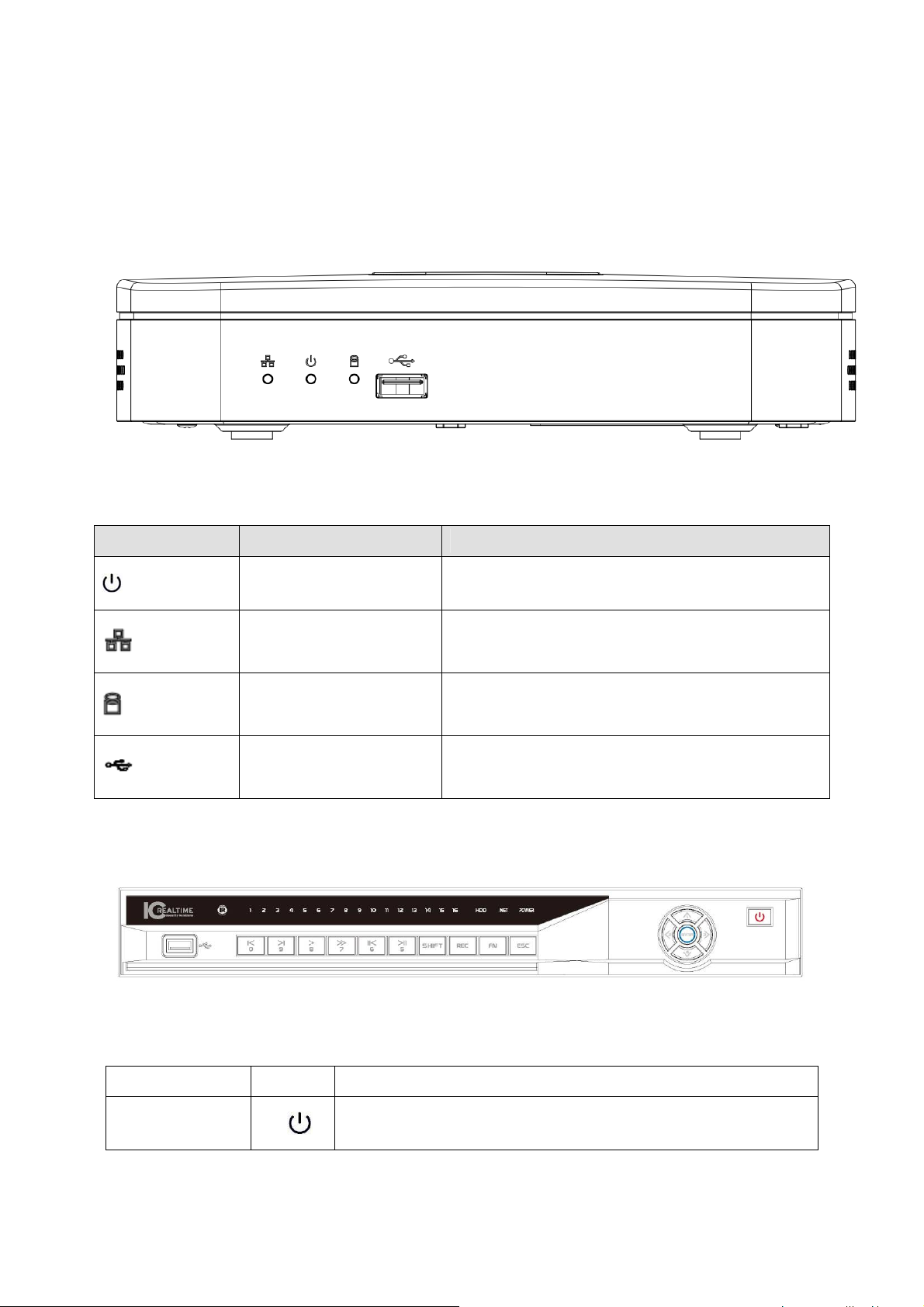
The front panel is shown as in Figure 2-1.
Figure 2-1
Please refer to the following sheet for detailed information.
Icon Name Function
Power indicator light
Network status indicator
light
HDD status indictor light
USB
The blue light becomes on when the power
connection is OK.
The blue light becomes on when the network
connection is abnormal or offline.
The red light becomes on when HDD is abnormal or
HDD space is below the threshold.
USB port. Connect to USB storage device, mouse
burner and etc.
2.1.2 NVR708S2-P/NVR716S2-P/NVR732S2-P Series
The front panel is shown as in Figure 2-2.
Figure 2-2
Please refer to the following sheet for detailed information.
Name Icon Function
Power button
Power button, press this button for three seconds to boot up
or shut down DVR.
8
Page 18

Shift Shift
Up/1
Down/4
Left/2
Right/3
ESC ESC
S、T
W X
In textbox, click this button to switch between numeral,
English(Small/Capitalized),donation and etc.
Activate current control, modify setup, and then move up and
down.
Increase/decrease numeral.
Assistant function such as PTZ menu.
In text mode, input number 1/4 (English character G/H/I)
Shift current activated control,
When playback, click these buttons to control playback bar.
In text mode, input number 2(English character A/B/C)
/3(English character D/E/F)
Go to previous menu, or cancel current operation.
When playback, click it to restore real-time monitor mode.
Confirm current operation
Enter ENTER
Record REC
Slow play/8
Assistant Fn
Go to default button
Go to menu
Manually stop/start recording, working with direction keys
or numeral keys to select the recording channel.
Multiple slow play speeds or normal playback.
In text mode, input number 8 (English character T/U/V).
One-window monitor mode, click this button to display
assistant function: PTZ control and image color.
Backspace function: in numeral control or text control, press
it for 1.5seconds to delete the previous character before the
cursor.
In motion detection setup, working with Fn and direction keys
to realize setup.
In text mode, click it to switch between numeral, English
character(small/capitalized) and etc.
Realize other special functions.
Fast play/7
Play
previous/0
_
Various fast speeds and normal playback.
In text mode, input number 7 (English character P/Q/R/S).
In playback mode, playback the previous video
In text mode, input number 0.
9
Page 19

Reverse/Pau
se/6
Play Next/9
Play/Pause /5
W
f
f
In normal playback or pause mode, click this button to
reverse
playback
In reverse playback, click this button to pause playback.
In playback mode, playback the next video
In menu setup, go to down ward of the dropdown list.
In text mode, input number 9 (English character W/X/Y/Z)
In normal playback click this button to pause playback
In pause mode, click this button to resume playback.
In text mode, input number 5(English character J/K/L).
USB port
Network
abnormal
indication
light
HDD
abnormal
indication
light
Record light 1-16
IR Receiver IR
Alarm
indication
light
Net
HDD
Alarm
To connect USB storage device, USB mouse.
Network error occurs or there is no network connection, the
light becomes red to alert you.
HDD error occurs or HDD capacity is below specified
threshold value, the light becomes red to alert you.
System is recording or not. It becomes on when system is
It is to receive the signal from the remote control.
Here you can view there is external alarm input or not. The
light becomes on when there is an external alarm. The light
become off when the external alarm stops.
2.1.3 NVR708X2/NVR716X2/NVR732X2 Series
The front panel is shown as in Figure 2-3.
Figure 2-3
Please refer to the following sheet for front panel button information.
Name Icon Function
Power button
Power button, press this button for three seconds to boot up
or shut down DVR.
10
Page 20

Number and
Character
0
1,. In text mode, input number 1 and denotation.
2ABC
3DEF
4GHI In text mode, input number 4 (English character G/H/I)
5JKL In text mode, input number 5(English character J/K/L).
6MNO
7PQRS In text mode, input number 7 (English character P/Q/R/S).
8TUV In text mode, input number 8 (English character T/U/V).
In text mode, input number 0.
It is the space button.
In text mode, input number 2(English character A/B/C)
In text mode, input number 3(English character D/E/F)
In text mode, input number 6 (English character M/N/O)
9WXYZ
-/--
Shift
Up
Down
Left
Right
ESC ESC
S、T
W X
In text mode, input number 9 (English character W/X/Y/Z)
If you want to input a number more than 10, please click this
button and then input.
In textbox, click this button to switch between numeral,
English(Small/Capitalized),donation and etc.
Activate current control, modify setup, and then move up and
down.
Increase/decrease numeral.
Assistant function such as PTZ menu.
Shift current activated control,
When playback, click these buttons to control playback bar.
Go to previous menu, or cancel current operation.
When playback, click it to restore real-time monitor mode.
Enter ENTER
Record REC
Window switch
Slow play/8
Assistant Fn
Mult
Confirm current operation
Go to default button
Go to menu
Manually stop/start recording, working with direction keys
or numeral keys to select the recording channel.
Click it to switch one-window/multiple-window.
Multiple slow play speeds or normal playback.
One-window monitor mode, click this button to display
assistant function: PTZ control and image color.
11
Page 21

Backspace function: in numeral control or text control, press
it for 1.5seconds to delete the previous character before the
cursor.
In motion detection setup, working with Fn and direction keys
to realize setup.
In text mode, click it to switch between numeral, English
character(small/capitalized) and etc.
Realize other special functions.
Fast play
Play previous
Reverse/Pau
se
Play Next
Play/Pause
USB port
Status
indication
light
_
W
f
f
Status
Various fast speeds and normal playback.
In playback mode, playback the previous video
In normal playback or pause mode, click this button to
reverse
playback
In reverse playback, click this button to pause playback.
In playback mode, playback the next video
In menu setup, go to down ward of the dropdown list.
In normal playback click this button to pause playback
In pause mode, click this button to resume playback.
To connect USB storage device, USB mouse.
If there is Fn indication light, current status indication light is
null.
HDD
abnormal
Remote
control
indication
light
Power
indication
light
Record light 1-16
HDD
ACT Remote control indication light
Power Power indication light
HDD error occurs or HDD capacity is below specified
threshold value, the light becomes red to alert you.
System is recording or not. It becomes on when system is
recording.
For this series product, the last 12 lights are null since there
is only four channels.
12
Page 22
IR Receiver IR
It is to receive the signal from the remote control.
Shuttle(outer
ring)
Jog(inner
dial)
CD-ROM
button
In real-time monitor mode it works as left/right direction key.
Playback mode, counter clockwise to forward and clock wise
to backward.
Up/down direction key.
Playback mode, turn the inner dial to realized frame by frame
playback. (Only applies to some special versions.)
Pop-up or insert the CD.
2.2 Rear Panel
2.2.1 NVR4i/NVR8i/ NVR4i-P/NVR8i-P Series
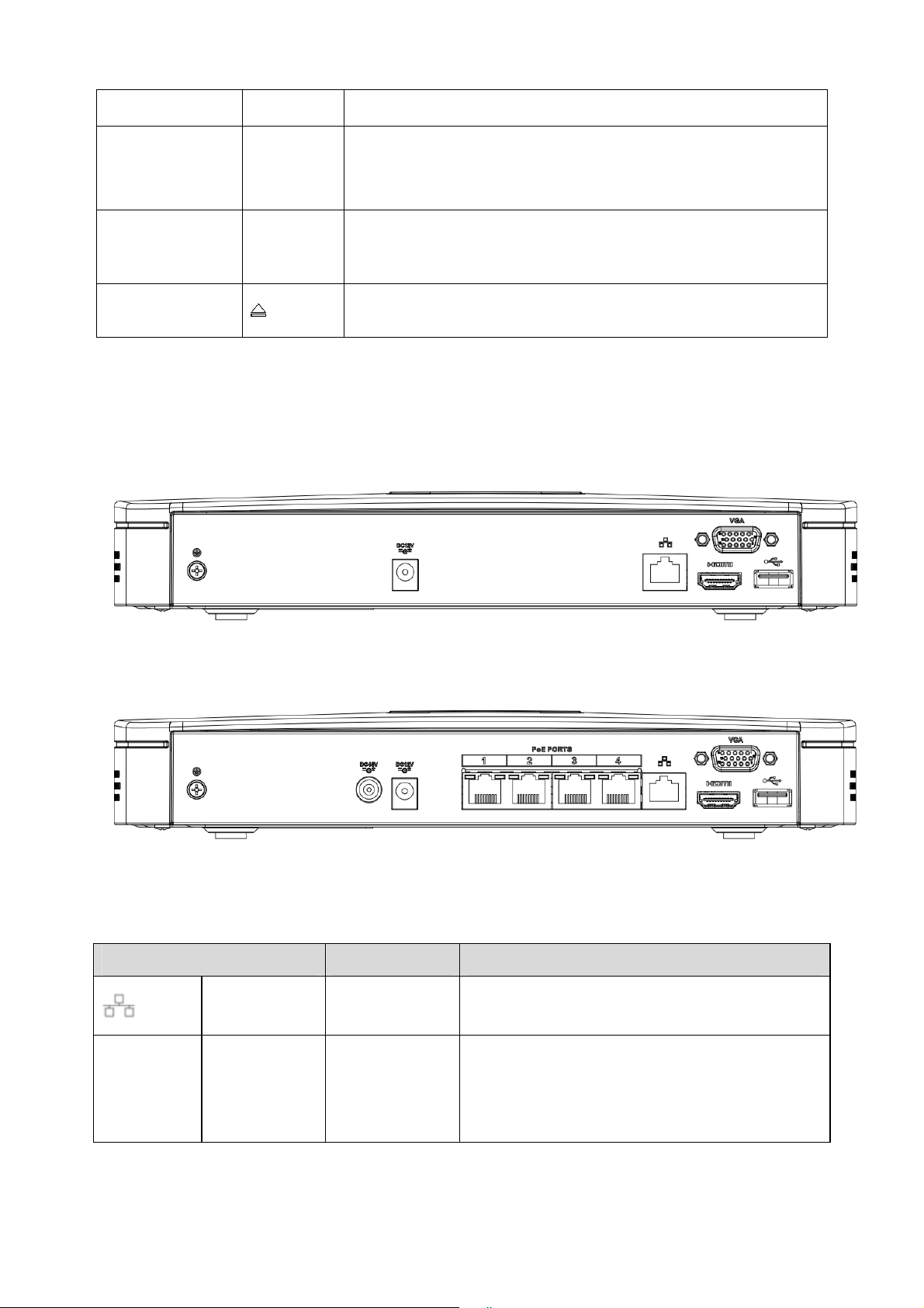
The NVR4i/NVR8i series rear panel is shown as below. See Figure 2-4.
Figure 2-4
The NVR4i-P/ NVR8i-P series rear panel is shown as below. See Figure 2-5.
Figure 2-5
Please refer to the following sheet for detailed information.
Port Name Connection Function
Network port / 10M/100/1000Mbps self-adaptive Ethernet port.
HDMI High Definition
Media
Interface
/ High definition audio and video signal output
Connect to the network cable.
port. It transmits uncompressed high definition
video and multiple-channel data to the HDMI port
of the display device.
13
Page 23
Port Name Connection Function
VGA VGA video
output port
PoE
PORTS
Wireless AP Support wireless hotspot function. Use WIFI to
GND / Alarm input port GND port.
Power input
port
Power input
port
4 PoE ports / Built-in Switch supports PoE function.
USB 2.0 port / USB 2.0 port. Conenct to mouse.
VGA VGA video output port. Output analog video
signal. It can connect to the monitor to view
analog video.
/ Power port. Input 12V DC.
/ Switch power port. Input DC 48V.
The 4 PoE ports series product supports total
48V 50W.
connect to the network camera when there is a
hotspot.
2.2.2 NVR708S2-P/NVR716S2-P/NVR732S2-P Series
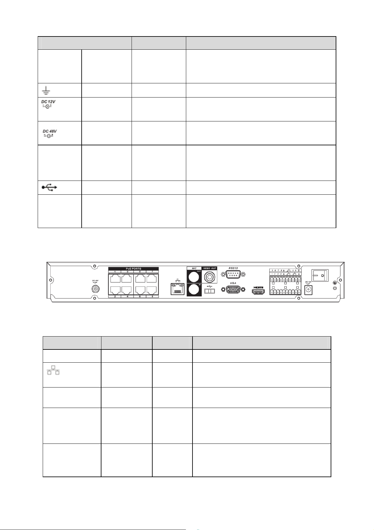
The rear panel is shown as below. See Figure 2-6.
Figure 2-6
Please refer to the following sheet for detailed information.
Port Name Connection Function
USB2.0 USB2.0 port. / Connect to USB2.0 mouse.
RS232 RS232 debug
HDMI High Definition
VGA
Network port / 10M/100M/1000Mbps self-adaptive Ethernet
port. Connect to the network cable.
/ It is for general COM debug to configure IP
COM.
Media
Interface
VGA video
output port
/ High definition audio and video signal output
VGA VGA video output port. Output analog video
address or transfer transparent COM data.
port. It transmits uncompressed high
definition video and multiple-channel data to
the HDMI port of the display device.
signal. It can connect to the monitor to view
analog video.
14
Page 24

Port Name Connection Function
1-8 Alarm input
I/O port
port 1-8.
Alarm input
port ground
end
NO1~NO3
C1~C3
Alarm output
port
1~3
z There are two groups. The first group is
from port 1 to port 4; the second group is
from port 5 to port 8. They are to receive
the signal from the external alarm
source. There are two types; NO (normal
open)/NC (normal close).
z When your alarm input device is using
external power, please make sure the
device and the NVR have the same
ground.
Alarm input ground end.
z 3 groups of alarm output ports. (Group
1:port NO1~C1,Group 2:port NO2~
C2,Group 3:port NO3 ~ C3 ) ).Output
alarm signal to the alarm device. Please
make sure there is power to the external
alarm device.
z NO:Normal open alarm output port.
z C:Alarm output public end.
A RS485_A port. It is the cable A. You can
RS485
(RS-485)
communication
connect to the control devices such as speed
dome PTZ.
port
B
RS485_B.It is the cable B. You can connect
to the control devices such as speed dome
PTZ.
Power input
port
/ Input 12V DC.
Power button / / Power on/off button.
PoE PORTS 8 PoE ports / Built-in Switch supports PoE function.
The 8 PoE ports series product supports total
48V 120W.
VIDEO OUT
Power input
port
Video input
port
MIC IN Audio input
port
/ Switch power port. Input DC 48V.
/ CVBS output
/ Bidirectional talk input port. It is to receive the
analog audio signal output from the devices
such as mike phone, pickup.
15
Page 25
Port Name Connection Function
MIC OUT Audio output
port
/ Audio output port. It is to output the analog
audio signal to the devices such as the sound
box.
z Bidirectional talk output.
z Audio output on 1-window video monitor.
z Audio output on 1-window video
playback.
2.2.3 NVR708X2/NVR716X2/NVR732X2 Series
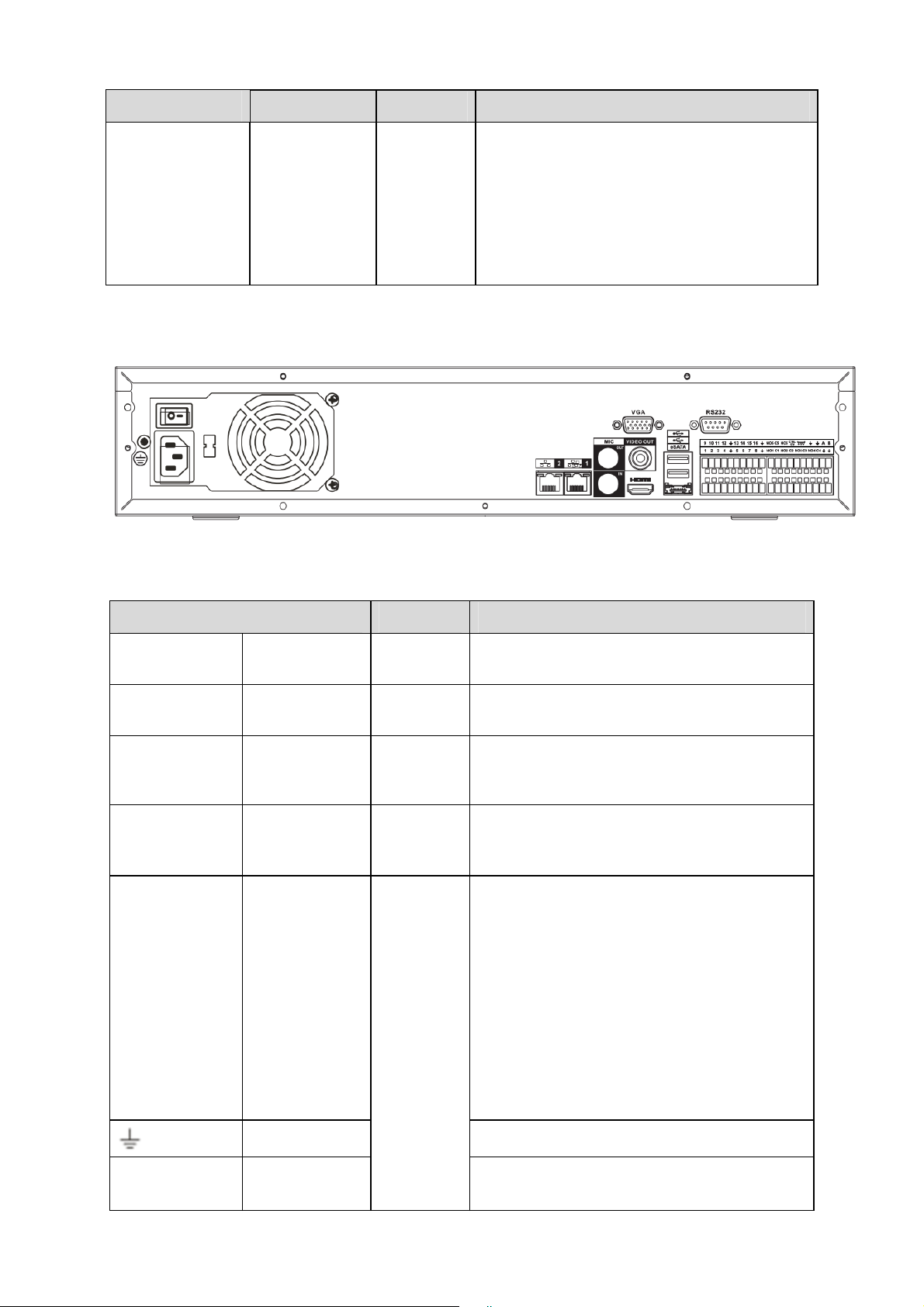
The rear panel is shown as below. See Figure 2-7.
Figure 2-7
Please refer to the following sheet for detailed information.
Port Name Connection Function
Power button / /
Power input
/ /
Power on/off button.
Input AC 220V power.
port
MIC IN Audio input
port
/
Bidirectional talk input port. It is to receive the
analog audio signal output from the devices
such as mike phone, pickup.
MIC OUT Audio output
port
/
Audio output port. It is to output the analog
audio signal to the devices such as the sound
box.
1-16 Alarm input
I/O port
port 1-16.
z There are four groups. The first group is
from port 1 to port 4, the second group is
from port 5 to port 8, the third group is
from 9 to 12, and the fourth group is from
13 to 16. They are to receive the signal
from the external alarm source. There
are two types; NO (normal open)/NC
(normal close).
z When your alarm input device is using
external power, please make sure the
device and the NVR have the same
ground.
Ground end Alarm input ground end.
NO1 to NO5 5-ch alarm
output port
z 5 groups of alarm output ports. (Group 1:
port NO1~C1,Group 2:port NO2~
16
Page 26

Port Name Connection Function
C1 to C5
C2,Group 3:port NO3~C3, Group 4:port
NO4~C4, Group 5: port NO5, C5,
NC5).Output alarm signal to the alarm
device. Please make sure there is power
NC5
A RS485_A port. It is the cable A. You can
RS485
(RS-485)
communication
B
port
to the external alarm device.
z NO: Normal open alarm output port.
z C: Alarm output public end.
z NC: Normal close alarm output port.
connect to the control devices such as speed
dome PTZ.
RS485_B.It is the cable B. You can connect
to the control devices such as speed dome
PTZ.
CTRL 12V / / Controller 12V power output. It is to control
the on-off alarm relay output. It can be used
to control the device alarm output. At the
same time, it can also be used as the power
input source of some devices such as the
alarm detector.
+12V / / +12V power output port. It can provide the
power to some peripheral devices such as
the camera or the alarm device. Please note
the supplying power shall be below 1A.
Network port / Two 10M/100M/1000M self-adaptive
Ethernet ports. Connect to the network cable.
eSATA eSATA port / External SATA port. It can connect to the
device of the SATA port. Please jump the
HDD when there is peripheral connected
HDD.
RS232(RS-422) RS232 debug
HDMI High Definition
USB port. Connect to USB mouse.
It is for general COM debug to configure IP
COM.
address or transfer transparent COM data.
High definition audio and video signal output
Media
Interface
port. It transmits uncompressed high
definition video and multiple-channel data to
the HDMI port of the display device.
VGA
VGA video
output port
VGA video output port. Output analog video
signal. It can connect to the monitor to view
analog video.
2.3 Alarm Connection
Please refer to the steps listed below.
z Connect the alarm input device to the alarm input port.
z Connect the alarm output device to the alarm output port. The NO and NC alarm output
17
Page 27
device can connect to the NO/C/NC port. For the NO alarm device, please connect to the
NO/C ports. For the NC alarm device, please connect to the NC/C ports. Please note the
NO/C ports are for NO alarm device only.
z Open Web, and go to the Alarm setup interface to set the alarm input and output. The alarm
01 is corresponding to the first channel of the device I/O port and so on. Please set the
NO/NC type according to the high/low level the alarm input device generated when an alarm
occurred
z Set the alarm output on the Web. The alarm output 01 is corresponding to the first group of
alarm out put port.
2.4 Bidirectional talk
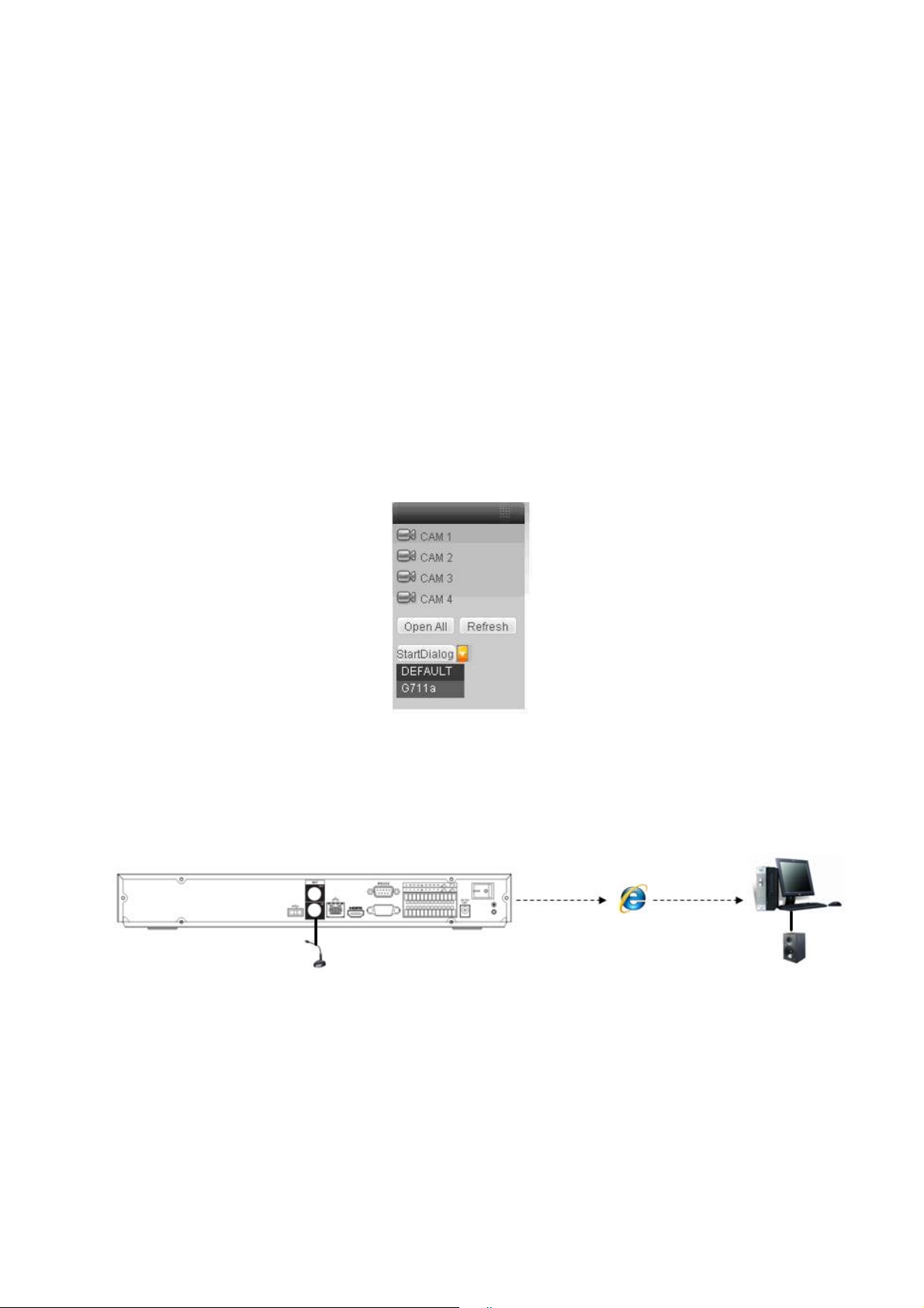
2.4.1 Device-end to PC-end
Device Connection
Please connect the speaker or the pickup to the first audio input port in the device rear panel.
Then connect the earphone or the sound box to the audio output port in the PC.
Login the Web and then enable the corresponding channel real-time monitor.
Please refer to the following interface to enable bidirectional talk. See Figure 2-8.
Figure 2-8
Listening Operation
At the device end, speak via the speaker or the pickup, and then you can get the audio from the
earphone or sound box at the pc-end. See Figure 2-9.
Figure 2-9
2.4.2 PC-end to the device-end
Device Connection
Connect the speaker or the pickup to the audio output port in the PC and then connect the
earphone or the sound box to the first audio input port in the device rear panel.
Login the Web and then enable the corresponding channel real-time monitor.
Please refer to the above interface (Figure 2-8) to enable bidirectional talk.
18
Page 28
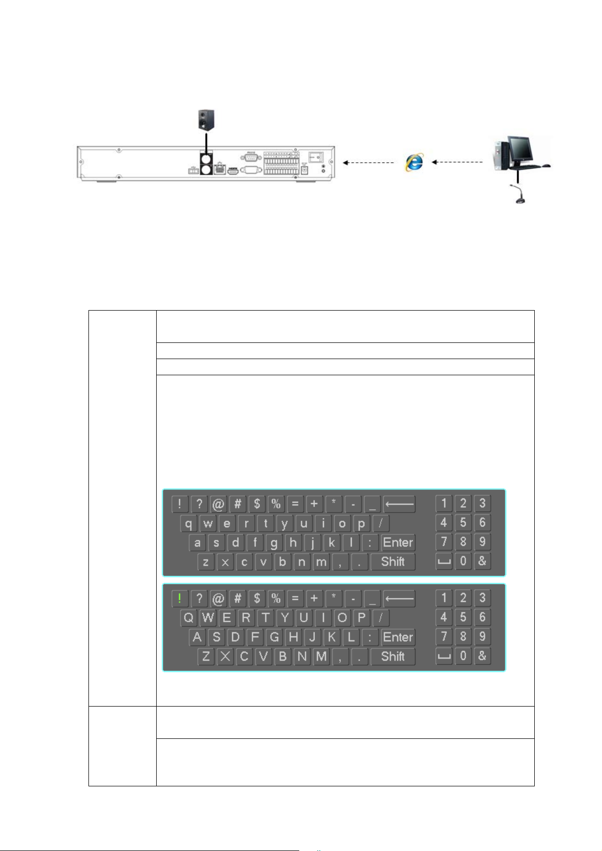
Listening Operation
At the PC-end, speak via the speaker or the pickup, and then you can get the audio from the
earphone or sound box at the device-end. See Figure 2-10.
Figure 2-10
2.5 Mouse Operation
Please refer to the following sheet for mouse operation instruction.
Left click
mouse
When you have selected one menu item, left click mouse to view menu
content.
Modify checkbox or motion detection status.
Click combo box to pop up dropdown list
In input box, you can select input methods. Left click the corresponding button
on the panel you can input numeral/English character (small/capitalized). Here
← stands for backspace button. _ stands for space button.
In English input mode: _stands for input a backspace icon and ← stands for
deleting the previous character.
Double left
click mouse
In numeral input mode: _ stands for clear and ← stands for deleting the
previous numeral.
Implement special control operation such as double click one item in the file list
to playback the video.
In multiple-window mode, double left click one channel to view in full-window.
Double left click current video again to go back to previous multiple-window
mode.
19
Page 29

Right click
mouse
Press
middle
button
Move
mouse
mouse
In real-time monitor mode, pops up shortcut menu.
Exit current menu without saving the modification.
In numeral input box: Increase or decrease numeral value.
Switch the items in the check box.
Page up or page down
Select current control or move control
Select motion detection zone Drag
Select privacy mask zone.
20
Page 30
3 HDD Installation
pp
(
y
Important:
Please turn off the power before you replace the HDD.
The pictures listed below for reference only.
For the first time install, please be aware that whether the HDDs have been installed.
You can refer to the Appendix for recommended HDD brand. Please use HDD of 7200rpm or
higher. Usually we do not recommend the PC HDD.
Please follow the instructions below to install hard disk.
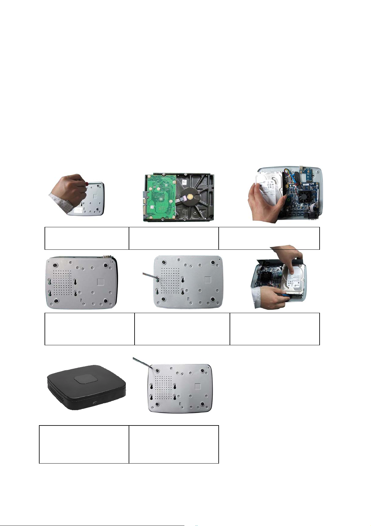
3.1 NVR4i/NVR8i/NVR4i-P/NVR8i-P Series
1. Loosen the screws of the
u
er cover and side panel.
2. Fix four screws in the HDD
Turn just three rounds).
3. Place the HDD in accordance with
the four holes in the bottom.
4. Turn the device upside down
and then turn the screws in
firml
.
5. Fix the HDD firmly.
6. Connect the HDD cable and
power cable.
7. Put the cover in accordance
with the clip and then place the
upper cover back.
8. Secure the screws in the
rear panel and the side panel.
3.2 NVR708S2-P/ NVR716S2-P/ NVR732S2-P Series
21
Page 31
pp
(
y
1. Loosen the screws of the
u
er cover and side panel.
4. Turn the device upside down
and then turn the screws in
firml
.
2. Fix four screws in the HDD
Turn just three rounds).
3. Place the HDD in accordance with
the four holes in the bottom.
5. Fix the HDD firmly.
6. Connect the HDD cable and
power cable.
7. Put the cover in accordance
with the clip and then place the
upper cover back.
8. Secure the screws in the rear
panel and the side panel.
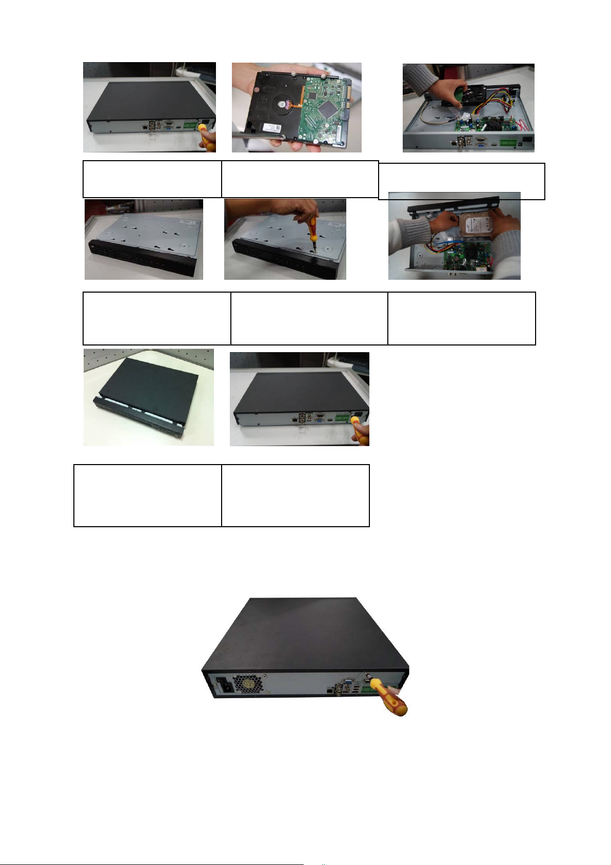
3.3 NVR708X2/ NVR716X2/ NVR732X2 Series
① Use the screwdriver to loose the screws of the rear panel and then remove the front cover.
22
Page 32

② Put the HDD to the HDD bracket in the chassis and then line up the four screws to the four
holes in the HDD. Use the screwdriver to fix the screws firmly to secure HDD on the HDD
bracket
③ Connect to the HDD data cable to the main board and the HDD port respectively. Loosen the
power cable of the chassis and connect another end of the power cable to the HDD port.
④ After connect the cable, put the front cover back to the device and then fix screws of the rear
panel.
23
Page 33

4 GUI Operation
Connect the device to the monitor and then connect a mouse and power cable. Click the power
button at the rear panel and then boot up the device to view the video output. You can use the
mouse to implement some GUI operation.
4.1 Login
After device booted up, the system is in multiple-channel display mode. See Figure 4-1.Please
note the displayed window amount may vary. The following figure is for reference only.
Figure 4-1
System consists of four accounts:
z Username: admin. Password: admin. (administrator, local and network)
z Username: 888888. Password: 888888. (administrator, local only)
z Username: 666666. Password: 666666(Lower authority user who can only monitor,
playback, backup and etc.)
z Username: default. Password: default(hidden user)
You can use USB2.0 mouse to input. Click
(small/capitalized) and denotation.
Note:
For security reason, please modify password after you first login.
Within 30 minutes, three times login failure will result in system alarm and five times login failure
will result in account lock!
to switch between numeral, English character
24
Page 34

Figure 4-2
You can overlay the corresponding date, time and channel name on each screen. You can refer to
the following sheet for channel record or alarm status information.
1
2
Preview Control
The preview control function has the following features.
z Support preview playback.
In the preview desktop, system can playback previous 5-60 minutes record of current
channel. Please go to the Main Menu->General to set real-time playback time.
Support drag and play function. You can use your mouse to select any playback start
time.
Support playback, pause and exit function.
Right now, system does not support slow playback and backward playback function.
z Support digital zoom function.
z Support real-time backup function.
You can follow the contents listed below for the operation instruction.
Preview control interface
Move you mouse to the top centre of the video of current channel, you can see system pops
up the preview control interface. See Figure 4-3. If your mouse stays in this area for more than
6 seconds and has no operation, the control bar automatically hides.
Recording status
Motion detection
1 2 3 4 5 6 7
3
4
Video loss
Camera lock
Figure 4-3
You can refer to the following sheet for detailed information.
SN Name Function
It is to playback the previous 5-60 minutes
1 Realtime playback
record of current channel.
Please go to the Main Menu->General to set
25
Page 35

real-time playback time.
System may pop up a dialogue box if there is no
such record in current channel.
It is to zoom in specified zone of current channel.
It supports zoom in function of multiple-channel.
2 Digital zoom
3
4 Manual Snap Click it to snap manually.
5
6 Bidirectional talk
Real-time backup
function
Remote device add
shortcut
The selected area has an icon as and the
free area is shown as an icon as
It is to backup the video of current channel to the
USB2.0 device. System can not backup the
video of multiple-channel at the same time.
Current selected backup channel has an icon as
and the free channel is shown as an icon
.
as
Once the backup started, you can see the free
channel is shown as an icon as
It is to go to the remote device connection
interface.
Support bidirectional talk function with the
front-end device.
.
.
7
Playback control
The playback control has the following features.
z Support play, pause, and exit and drag function.
z During the preview playback process, you can not see the channel title and record status
of current channel. It will display the channel title and the record status once you exit the
preview playback.
z During the preview playback, you can not switch the displayed channel or change current
window-display mode.
z Please note, the tour function has the higher priority than the preview playback. System
automatically exits the preview playback function and its corresponding interface when
the tour function started. You can not control the preview playback until the tour function
ended.
Exit
4.2 Right Click Menu
After you logged in the device, right click mouse, you can see the short cut menu. Please see
Figure 4-4.
26
Page 36

Here you can set local playback window, PTZ control, video color, search records, remote device
and etc. The local playback window includes 1/4/8/9/16. You can set the detail channel amount in
1/4-window.
Figure 4-4
4.3 Main Menu
After you logged in, the system main menu is shown as below. See Figure 4-5. There are total
seven icons: search, Information, setting, remote device, backup, advanced and shutdown. Move
the cursor to highlight the icon, then double click mouse to enter the sub-menu.
Figure 4-5
4.4 Search & Playback
Click search button in the main menu, search interface is shown as below. See Figure 4-6.
27
Page 37

2
1
7
8
12
Figure 4-6
Please refer to the following sheet for more information.
11
3
4
56
10
9
SN Name Function
1
Display
window
z Here is to display the searched picture or file.
z Support 1/4/9/16-window playback.
z Here you can select to search the picture or the recorded file.
z You can select to play from the read-write HDD, from peripheral device or from
redundancy HDD.
z Before you select to play from the peripheral device, please connect the
corresponding peripheral device. You can view all record files of the root directory
of the peripheral device. Click the Browse button; you can select the file you want to
play.
2
Search
type
Important
Redundancy HDD does not support picture backup function, but it supports picture
playback function. You can select to play from redundancy HDD if there are pictures
on the redundancy HDD.
z The blue highlighted date means there is picture or file. Otherwise, there is no
3 Calendar
picture or file.
z In any play mode, click the date you want to see, you can see the
corresponding record file trace in the time bar.
z Playback mode:1/4/9/16. (It may vary due to different series.)
In 1-window playback mode: you can select 1-16 channels.
In 4-window playback mode: you can select 4 channels according to your
requirement.
4
Playback
mode
and
channel
28
Page 38

5
selection
pane.
File list
switch
button
In 9-window playback mode, you can switch between 1-8 and 9-16 channels.
In 16-window playback mode, you can switch between1-16 and 17-32
channels.
z The time bar will change once you modify the playback mode or the channel
option.
z Double click it, you can view the picture/record file list of current day.
z The file list is to display the first channel of the record file.
z The system can display max 128 files in one time. Use the S/T or the mouse
to view the file. Select one item, and then double click the mouse or click the
ENTER button to playback.
z You can input the period in the following interface to begin accurate search.
z File type:R—regular record; A—external alarm record;M—Motion detect
record.
z Lock file. Click the file you want to lock and click the button
file you locked will not be overwritten.
to lock. The
6
7
Card
number
search
Playback
control
pane.
z Search locked file: Click the button
z Return: Click button
interface.
Please note:
z System max locks 16 files. The size of the locked file shall be less than the 1/4
of the HDD total space. The first 16G of each partition can not be locked.
z System can only lock one file at one time and can not lock the extra stream. For
the file that is writing or overwriting, it can not be locked.
The card number search interface is shown as below.
Play/Pause
There are three ways for you to begin playback.
►/
■ Stop
W
z The play button
z Double click the valid period of the time bar.
z Double click the item in the file list.
In slow play mode, click it to switch between play/pause.
Backward play
In normal play mode, left click the button, the file begins backward play.
Click it again to pause current play.
In backward play mode, click ►/ to restore normal play.
, system goes back to the calendar and channel setup
to view the locked file.
│W/
X│
In playback mode, click it to play the next or the previous section. You can
click continuously when you are watching the files from the same channel.
In normal play mode, when you pause current play, you can click W│ and
29
Page 39

│X to begin frame by frame playback.
In frame by frame playback mode, click ►/ to restore normal playback.
►
Note: The actual play speed has relationship with the software version.
z It is to display the record type and its period in current search criteria.
z In 4-window playback mode, there are corresponding four time bars. In other
playback mode, there is only one time bar.
z Use the mouse to click one point of the color zone in the time bar, system
8 Time bar
9
10 Backup
11 Clip
12 Record In any play mode, the time bar will change once you modify the search type.
Time bar
unit
begins playback.
z The time bar is beginning with 0 o'clock when you are setting the configuration.
The time bar zooms in the period of the current playback time when you are playing
the file.
z The green color stands for the regular record file. The red color stands for the
external alarm record file. The yellow stands for the motion detect record file.
●The option includes: 24H, 12H, 1H and 30M. The smaller the unit, the larger the
zoom rate. You can accurately set the time in the time bar to playback the record.
z The time bar is beginning with 0 o'clock when you are setting the configuration.
The time bar zooms in the period of the current playback time when you are playing
the file.
Select the file(s) you want to backup from the file list. System max supports files
from four channels. Then click the backup button, now you can see the backup
menu. Click the start button to begin the backup operation.
Check the file again you can cancel current selection.
System max supports to display 32 files from one channel.
z It is to edit the file.
●Please play the file you want to edit and then click this button when you want to
edit. You can see the corresponding slide bar in the time bar of the corresponding
channel. You can adjust the slide bar or input the accurate time to set the file end
time. Click this button again and then save current contents in a new file. .
Slow play
In playback mode, click it to realize various slow play modes such as slow
play 1, slow play 2, and etc.
Fast forward
In playback mode, click to realize various fast play modes such as fast
play 1,fast play 2 and etc.
Smart search
The volume of the playback
Click the snapshot button in the full-screen mode, the system can snapshot
1 picture per second.
System supports custom snap picture saved path. Please connect the
peripheral device first, click snap button on the full-screen mode, you can
select or create path. Click Start button, the snapshot picture can be saved
to the specified path.
30
Page 40

13
type
Smart
search
z When system is playing, you can select a zone in the window to begin motion
detect. Click the motion detect button to begin play.
z Current button is null once the motion detect play has begun.
z The system will take the whole play zone as the motion detect region by
default.
z The motion detect play stopped once you switch the play file.
z Operations such as set time bar, click the play button, or any file list operation
will stop current motion detect play.
Other Functions
14
15 Digital zoom
16
Note:
All the operations here (such as playback speed, channel, time and progress) have
relationship with hardware version. Some series NVRs do not support some functions or
playback speeds.
Other channel
synchronization switch to play
when playback
Manually switch channel
when playback
When playing the file, click the number button, system can
switch to the same period of the corresponding channel to play.
When the system is in full-screen playback mode, left click
the mouse in the screen. Drag your mouse in the screen to
select a section and then left click mouse to realize digital
zoom. You can right click mouse to exit.
During the file playback process, you can switch to other
channel via the dropdown list or rolling the mouse.
This function is null if there is no record file or system is in
smart search process.
4.5 Information
Here is for you to view system information. There are total seven items: HDD (hard disk
information), BPS (data stream statistics), log, Version, online user, remote device information
and network info. See Figure 4-7.
Figure 4-7
31
Page 41

4.5.1 HDD Information
Here is to list hard disk type, total space, free space, and status. See Figure 4-8.
○ means current HDD is normal.. - means there is no HDD.
If disk is damaged, system shows as “?”. Please remove the broken hard disk before you add a
new one.
Figure 4-8
In Figure 4-8, click view record d time button, HDD record time information interface is shown as
in Figure 4-9.
Figure 4-9
Parameter Function
SATA
1-4 here means there are 4 HDDS.
When HDD is working properly, system is shown as O. . “_” means there is
no HDD.
SN You can view the HDD amount the device connected to;
﹡ means the second HDD is current working HDD.
Type The corresponding HDD property.
Total space The HDD total capacity.
32
Page 42

Free space The HDD free capacity.
Status HDD can work properly or not.
Bad track Display there is bad track or not.
Page up Click it to view previous page.
Page down Click it to view the next page.
View
recording time
View HDD
type and
capability
Click it to view HDD record information (file start time and end time).
Click it to view HDD property, status and etc,
4.5.2 BPS
Here is for you to view current video data stream (KB/s) and occupied hard disk storage (MB/h).
See Figure 4-10.
Figure 4-10
For the 32-channel series product, the interface is shown as below. See Figure 4-11.
Figure 4-11
33
Page 43

4.5.3 Log
Here is for you to view system log file. System lists the following information. See Figure 4-12.
Log types include system operation, configuration operation, data management, alarm event,
record operation, log clear and etc.
z Start time/end time: Pleased select start time and end time, then click search button. You can
view the log files in a list. System max displays 100 logs in one page. It can max save 1024
log files. Please use page up/down button on the interface or the front panel to view more.
z Backup: Please select a folder you want to save; you can click the backup button to save the
log files. After the backup, you can see there is a folder named Log_time on the backup path.
Double click the folder, you can see the log file
z Details: Click the Details button or double click the log item, you can view the detailed
information. See Figure 4-13. Here you can use rolling bar to view information, or you can
use Page up/Page down to view other log information. For the alarm event log such as video
loss, you can click the Playback button at the bottom right corner to playback.
Figure 4-12
Figure 4-13
34
Page 44
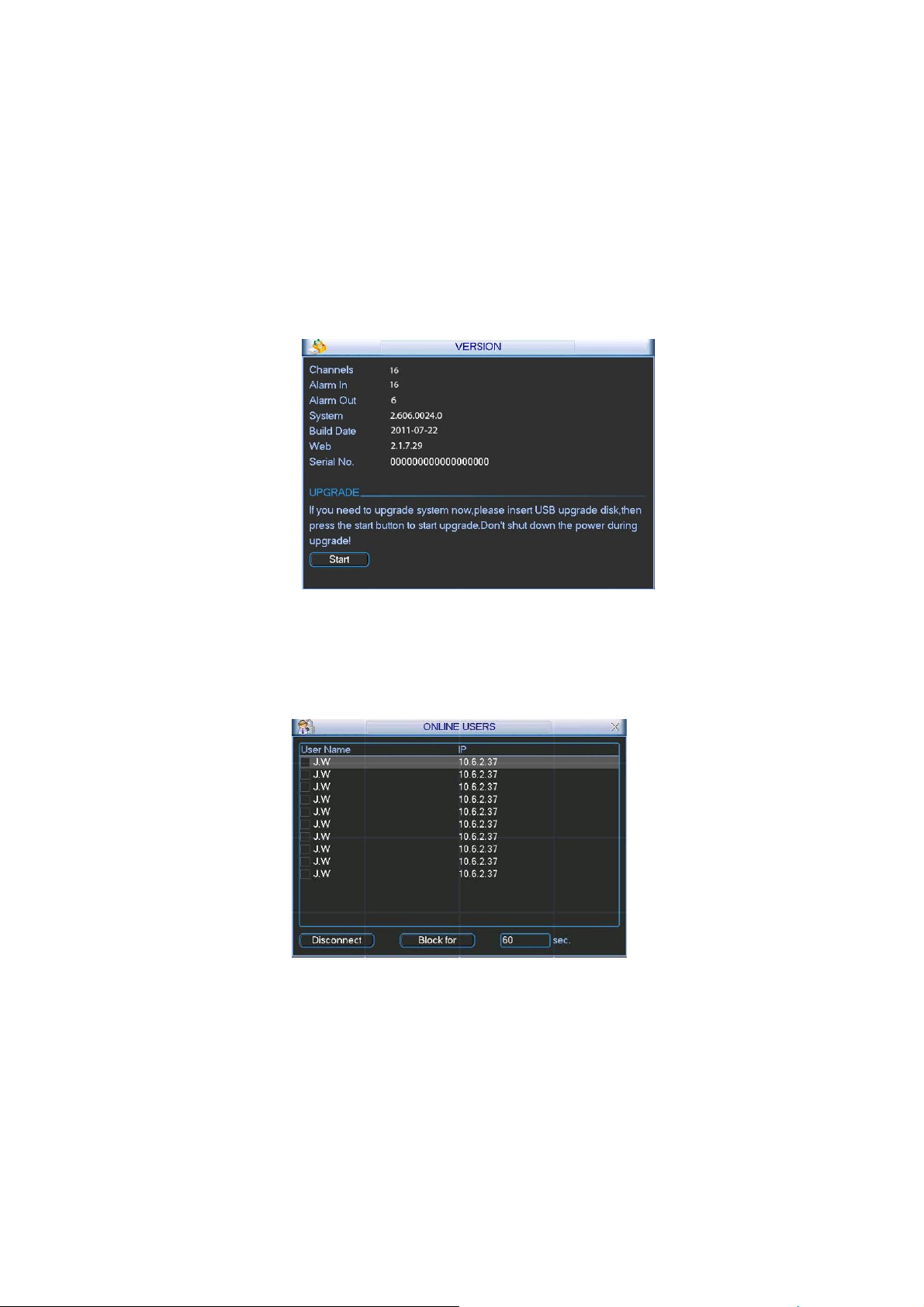
4.5.4 Version
Here is for you to view some version information. See Figure 4-14.
z Channel
z Alarm in
z Alarm out
z System version:
z Build Date
z Web
z Serial number
Figure 4-14
4.5.5 Online Users
Here is for you manage online users connected to the local device. See Figure 4-15.
You can disconnect one user or block one user if you have proper system right.
Figure 4-15
4.5.6 Remote Device Information
Here you can view the channel status of the remote device, connection log and etc.
Channel status: Here you can view the IPC status of the corresponding channel such as motion
detect, video loss, camera masking, alarm and etc. See Figure 4-16.
35
Page 45

Figure 4-16
Connection log: In this interface, you can search the IPC log information of the corresponding
channel. It includes IPC online, offline and etc. See Figure 4-17.
Figure 4-17
4.5.7 Network Info
In this interface, you can see network test and network load information.
4.5.7.1 Network Test
Network test interface is shown as in Figure 4-18.
Destination IP: Please input valid IPV4 address and domain name.
Test: Click it to test the connection with the destination IP address. The test results can display
average delay and packet loss rate and you can also view the network status as OK, bad, no
36
Page 46

connection and etc.
Network Sniffer backup: Please insert USB2.0 device and click the Refresh button, you can view
the device on the following column. You can use the dropdown list to select peripheral device.
Click Browse button to select the snap path. The steps here are same as preview backup
operation.
You can view all connected network adapter names (including Ethernet, PPPoE, WIFI, and 3G),
you can click the button
Please note system can not Sniffer several network adapters at the same time.
After Sniffer began, you can exit to implement corresponding network operation such as login
WEB, monitor. Please go back to Sniffer interface to click
packets to the specified path. The file is named after “Network adapter name+time”. You can use
software such as Wireshark to open the packets on the PC for the professional engineer to solve
complicated problems.
on the right panel to begin Sniffer. Click the grey stop button to stop.
stop Sniffer. System can save the
Figure 4-18
4.5.7.2 Network Load
Network load is shown as in Figure 4-19. Here you can view the follow statistics of the device
network adapter.
Here you can view information of all connected network adapters. The connection status is shown
as offline if connection is disconnected. Click one network adapter, you can view the flow statistics
such as send rate and receive rate at the top panel
37
Page 47

Figure 4-19
4.6 Setting
In main menu, highlight setting icon and double click mouse. System setting interface is shown as
below. See Figure 4-20.
Figure 4-20
Important
Please note you need to have the proper right to implement the following operation.
4.6.1 General
General setting includes the following items. See Figure 4-21.
z System time: Here is for you to set system time
z Date format: There are three types: YYYYY-MM-DD: MM-DD-YYYYY or DD-MM-YYYY.
z Date separator: There are three denotations to separate date: dot, beeline and solidus.
38
Page 48

z DST: Here you can set DST time and date. Please enable DST function and then click set
button. You can see an interface is shown as in Figure 4-22. Here you can set start time and
end time by setting corresponding week setup. In Figure 4-22, enable date button, you can
see an interface is shown as in Figure 4-23. Here you can set start time and end time by
setting corresponding date setup.
z Time format: There are two types: 24-hour mode or 12-hour mode.
z Language: System supports various languages: Chinese (simplified), Chinese (Traditional),
English, Italian, Japanese, French, Spanish (All languages listed here are optional. Slight
difference maybe found in various series.)
z HDD full: Here is for you to select working mode when hard disk is full. There are two options:
stop recording or rewrite. If current working HDD is overwritten or the current HDD is full while
the next HDD is no empty, then system stops recording, If the current HDD is full and then
next HDD is not empty, then system overwrites the previous files.
z Pack duration: Here is for you to specify record duration. The value ranges from 60 to 120
minutes. Default value is 60 minutes.
z Device No: When you are using one remote control (not included in the accessory bag) to
control several NVRs, you can give a name to each NVR for your management.
z Video standard: There are two formats: NTSC and PAL.
z Realtime play: It is to set playback time you can view in the preview interface. The value
ranges from 5 to 60 minutes.
z Device ID: Please input a corresponding device name here.
z Holiday setting: Click it you can see an interface shown as in Figure 4-24. Here you can set
holiday date. Please go to the Holidays Period interface to set the holiday date record setup.
When you enable Holiday settings and schedule setup at the same time, holiday setting
has the priority. If the selected day is a holiday, then system records as you set in holiday
setting. If it is not a holiday, system records as you set in Schedule interface. Please note
you need to go to chapter 4.6.3 Schedule to enable Holiday setup. Otherwise you can not
enable holiday record setup.
Please note, there is no year setup on the holiday setting. For example, if you set 30th
Oct, 2012 as a holiday, then the date of 30th Oct in each year will be set as a holiday. So,
general speaking, your holiday setup in other year may also affect the holiday setup in
2012.
z Mouse property: Click mouse setup button, you can go to mouse setup interface. See Figure
4-25. You can set double click speed via dragging the slide bard. You can Click Default
button to restore default setup.
z Startup wizard: Once you check the box here, system will go to the startup wizard directly
when the system restarts the next time. Otherwise, it will go to the login interface.
z Auto logout: Here is for you to set auto logout interval once login user remains inactive for a
specified time. Value ranges from 0 to 60 minutes.
z Navigation bar: Check the box here, system displays the navigation bar on the interface.
z IPC Time Sync: You can input an interval here to synchronize the NVR time and IPC time.
z Snap times: Here you can set snap picture amount of one click.
Note:
Since system time is very important, do not modify time casually unless there is a must!
Before your time modification, please stop record operation first!
After completing all the setups please click save button, system goes back to the previous menu.
39
Page 49
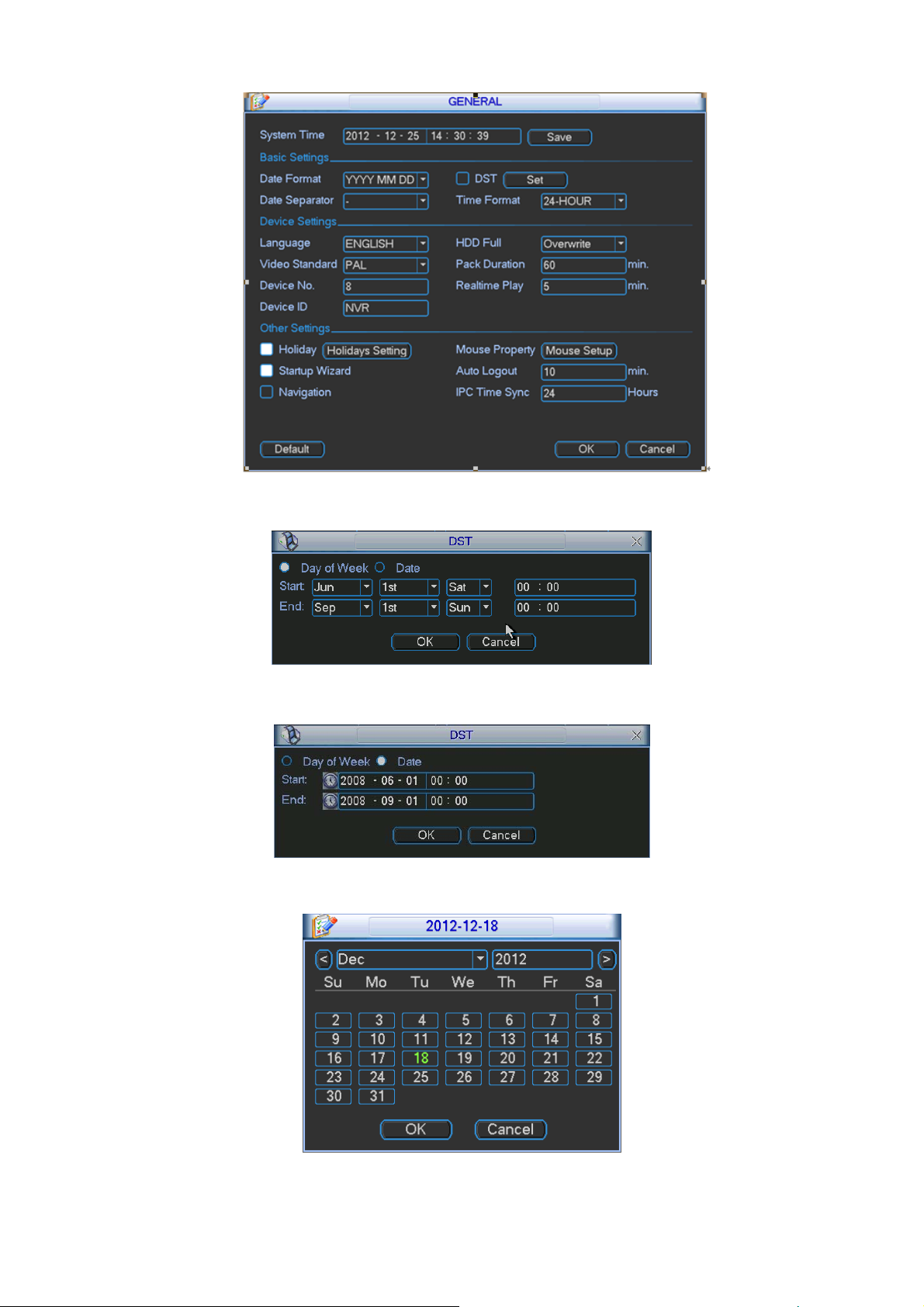
Figure 4-21
Figure 4-22
Figure 4-23
Figure 4-24
40
Page 50

Figure 4-25
4.6.2 Encode
Encode setting includes the following items. See Figure 4-26.
Please note some series do not support extra stream.
z Channel: Select the channel you want.
z Type: Please select from the dropdown list. There are three options: regular/motion
detect/alarm. You can set the various encode parameters for different record types.
z Compression: System supports H.264, MPEG4, MJPEG and etc.
z Resolution: The mainstream resolution type is IPC’s encoding config. Generally there is
D1/720P/1080P.
z Frame rate: It ranges from 1f/s to 25f/s in NTSC mode and 1f/s to 30f/s in PAL mode.
z Bit rate type: System supports two types: CBR and VBR. In VBR mode, you can set video
quality.
z Quality: There are six levels ranging from 1 to 6. The sixth level has the highest image
quality.
z Video/audio: You can enable or disable the video/audio.
z Overlay: Click overlay button, you can see an interface is shown in Figure 4-27.
Cover area (Privacy mask): Here is for you to set privacy mask section. You can drag you
mouse to set proper section size. In one channel video, system max supports 4 zones in
one channel.
Preview/monitor: privacy mask has two types. Preview and Monitor. Preview means the
privacy mask zone can not be viewed by user when system is in preview status. Monitor
means the privacy mask zone can not be view by the user when system is in monitor
status.
Time display: You can select system displays time or not when you playback. Please
click set button and then drag the title to the corresponding position in the screen.
Channel display: You can select system displays channel number or not when you
playback. Please click set button and then drag the title to the corresponding position in
the screen.
Copy:After you complete the setup, you can click Copy button to copy current setup to
other channel(s). You can see an interface is shown as in Figure 4-28. You can see
current channel number is grey. Please check the number to select the channel or you
can check the box ALL. Please click the OK button in Figure 4-28 and Figure 4-26
respectively to complete the setup. Please note, once you check the All box, you set
same encode setup for all channels. Audio/video enable box, overlay button and the
copy button is shield. See Figure 4-29.
41
Page 51

Please highlight icon
to select the corresponding function.
Figure 4-26
Figure 4-27
Figure 4-28
42
Page 52

Figure 4-29
4.6.3 Schedule
In the main menu, from setting to schedule, you can go to schedule menu. See Figure 4-30.
z Channel: Please select the channel number first. You can select “all” if you want to set for the
whole channels.
z Week day: There are eight options: ranges from Saturday to Sunday and all.
z Pre-record: System can pre-record the video before the event occurs into the file. The value
ranges from 1 to 30 seconds depending on the bit stream.
z Redundancy: System supports redundancy backup function. It allows you backup recorded
file in two disks. You can highlight Redundancy button to activate this function. Please note,
before enable this function, please set at least one HDD as redundant. (Main
menu->Advanced->HDD Management). Please note this function is null if there is only
one HDD.
z Snapshot: You can enable this function to snapshoot image when an alarm occurs.
z Record types: There are four types: regular, motion detection (MD), Alarm, MD & alarm.
z Holiday: Highlight the button here, the holiday settings in General interface (Chapter 4.6.1)
becomes activated.
Please highlight icon
please click save button, system goes back to the previous menu.
At the bottom of the menu, there are color bars for your reference. Green color stands for
regular recording, yellow color stands for motion detection and red color stands for alarm
recording. The white means the MD and alarm record is valid. Once you have set to record
when the MD and alarm occurs, system will not record neither motion detect occurs nor the
alarm occurs.
to select the corresponding function. After completing all the setups
43
Page 53

Figure 4-30
4.6.3.1 Quick Setup
Copy function allows you to copy one channel setup to another. After setting in channel 1, click
Copy button, you can go to interface Figure 4-31. You can see current channel name is grey such
as channel 1. Now you can select the channel you wan to paste such as channel 5/6/7. If you wan
to save current setup of channel 1 to all channels, you can click the first box “ALL”. Click the OK
button to save current copy setup. Click the OK button in the Encode interface, the copy function
succeeded.
Please note, if you select ALL in Figure 4-31, the record setup of all channels are the same and
the Copy button becomes hidden.
Figure 4-31
4.6.4 RS232
RS232 interface is shown as below. There are five items. See Figure 4-32.
z Function: There are various devices for you to select. Console is for you to use the COM or
mini-end software to upgrade or debug the program. The control keyboard is for you to
control the device via the special keyboard. Transparent COM (adapter) is to connect to the
PC to transfer data directly. Protocol COM is for card overlay function. Network keyboard is
for you to use the special keyboard to control the device. PTZ matrix is to connect to the
peripheral matrix control.
z Baud rate: You can select proper baud rate.
44
Page 54

z Data bit: You can select proper data bit. The value ranges from 5 to 8.
z Stop bit: There are three values: 1/1.5/2.
z Parity: there are five choices: none/odd/even/space mark.
System default setup is:
z Function: Console
z Baud rate:115200
z Data bit:8
z Stop bit:1
z Parity: None
After completing all the setups please click save button, system goes back to the previous menu.
Figure 4-32
4.6.5 Network
Here is for you to input network information. See Figure 4-33.
z IP Version: There are two options: IPv4 and IPv6. Right now, system supports these two IP
address format and you can access via them.
z MAC address: The host in the LAN can get a unique MAC address. It is for you to access in the
LAN. It is read-only.
z IP address: Here you can use up/down button (
input IP address. Then you can set the corresponding subnet mask the default gateway.
z Subnet prefix: The input value ranges from 0 to 128. It is to mark a specified network MAC
address. Usually it includes an organization of multiple-level.
z Default gateway: Here you can input the default gateway. Please note system needs to
check the validity of all IPv6 addresses. The IP address and the default gateway shall
be in the same IP section. That is to say, the specified length of the subnet prefix shall
have the same string.
z DHCP: It is to auto search IP. When enable DHCP function, you can not modify IP/Subnet
mask /Gateway. These values are from DHCP function. If you have not enabled DHCP
function, IP/Subnet mask/Gateway display as zero. You need to disable DHCP function to
view current IP information. Besides, when PPPoE is operating, you can not modify
IP/Subnet mask /Gateway.
z TCP port: Default value is 37777. You can change if necessary.
z UDP port: Default value is 37778. You can change if necessary.
ST) or input the corresponding number to
45
Page 55

z HTTP port: Default value is 80.
z RTSP port: Default value is 554.
Important: System needs to reboot after you changed and saved any setup of the above
four ports. Please make sure the port values here do not conflict.
z Max connection: system support maximal 20 users. 0 means there is no connection limit.
z MTU: It is to set MTU value of the network adapter. The value ranges from 1280-7200 bytes.
The default setup is 1500 bytes. Please note MTU modification may result in network adapter
reboot and network becomes off. That is to say, MTU modification can affect current network
service. System may pop up dialog box for you to confirm setup when you want to change
MTU setup. Click OK button to confirm current reboot, or you can click Cancel button to
terminate current modification. Before the modification, you can check the MTU of the
gateway; the MTU of the NVR shall be the same as or is lower than the MTU of the gateway.
In this way, you can reduce packets and enhance network transmission efficiency.
The following MTU value is for reference only.
1500: Ethernet information packet max value and it is also the default value. It is the
typical setup when there is no PPPoE or VPN. It is the default setup of some router,
switch or the network adapter.
1492: Recommend value for PPPoE.
1468: Recommend value for DHCP.
Please make sure MTU port does not conflict with other ports.
z Preferred DNS server: DNS server IP address.
z Alternate DNS server: DNS server alternate address.
z Transfer mode: Here you can select the priority between fluency/video qualities.
z LAN download: System can process the downloaded data first if you enable this function. The
download speed is 1.5X or 2.0X of the normal speed.
Important
For the IP address of IPv6 version, default gateway, preferred DNS and alternate DNS, the
input value shall be 128-digit. It shall not be left in blank.
After completing all the setups please click save button, system goes back to the previous menu.
Figure 4-33
4.6.5.1 Network Setting
Network setting interface is shown as in Figure 4-34. Please draw a circle to enable
corresponding function and then double click current item to go to setup interface.
46
Page 56

Figure 4-34
4.6.5.2 IP Filter
IP filter interface is shown as in Figure 4-35. You can add IP in the following list. The list supports
max 64 IP addresses. System supports valid address of IPv4 and IPv6. Please note system
needs to check the validity of all IPv6 addresses.
After you enabled trusted sites function, only the IP listed below can access current NVR.
If you enable blocked sites function, the following listed IP addresses can not access current NVR.
z Enable: Highlight the box here, you can check the trusted site function and blocked sites
function. You can not see these two modes if the Enable button is grey.
z Type: You can select trusted site and blacklist from the dropdown list. You can view the IP
address on the following column.
z Start address/end address: Select one type from the dropdown list, you can input IP address
in the start address and end address. Now you can click Add IP address or Add IP section to
add.
a) For the newly added IP address, it is in enable status by default. Remove the √ before
the item, then current item is not in the list.
b) System max supports 64 items.
c) Address column supports IPv4 or IPv6 format. If it is IPv6 address, system can optimize
it. For example, system can optimize aa:0000: 00: 00aa: 00aa: 00aa: 00aa: 00aa as aa::
aa: aa: aa: aa: aa: aa.
d) System automatically removes space if there is any space before or after the newly
added IP address.
e) System only checks start address if you add IP address. System check start address and
end address if you add IP section and the end address shall be larger than the start
address.
f) System may check newly added IP address exists or not. System does not add if input IP
address does not exist.
z Delete: Click it to remove specified item.
z Edit: Click it to edit start address and end address. System can check the IP address validity
after the edit operation and implement IPv6 optimization.
47
Page 57

Figure 4-35
4.6.5.3 NTP Setup
You need to install SNTP server (Such as Absolute Time Server) in your PC first. In Windows XP
OS, you can use command “net start w32time” to boot up NTP service.
NTP setup interface is shown as in Figure 4-36.
z Host IP: Input your PC address.
z Port: This series NVR supports TCP transmission only. Port default value is 123.
z Update interval: minimum value is 1. Max value is 65535. (Unit: minute)
z Time zone: select your corresponding time zone here.
z Update period: You can input interval here.
z Manual update: It allows you to synchronize the time with the server manually.
Here is a sheet for your time zone setup.
City /Region Name Time Zone
London GMT+0
Berlin GMT+1
Cairo GMT+2
Moscow GMT+3
New Deli GMT+5
Bangkok GMT+7
Beijing (Hong Kong) GMT+8
Tokyo GMT+9
Sydney GMT+10
Hawaii GMT-10
Alaska GMT-9
Pacific Time(P.T) GMT-8
American Mountain Time(M.T) GMT-7
American Central Time(C.T) GMT-6
American Eastern Time(E.T) GMT-5
Atlantic Time GMT-4
48
Page 58

Brazil GMT-3
Middle Atlantic Time GMT-2
Figure 4-36
4.6.5.4 Multicast
Multiple-cast setup interface is shown as in Figure 4-37.
Figure 4-37
Here you can set a multiple cast group. Please refer to the following sheet for detailed information.
z IP multiple cast group address
-224.0.0.0-239.255.255.255
-“D” address space
z The higher four-bit of the first byte=”1110”
z Reserved local multiple cast group address
-224.0.0.0-224.0.0.255
-TTL=1 When sending out telegraph
-For example
224.0.0.1 All systems in the sub-net
224.0.0.2 All routers in the sub-net
224.0.0.4 DVMRP router
224.0.0.5 OSPF router
224.0.0.13 PIMv2 router
z Administrative scoped addressees
-239.0.0.0-239.255.255.255
-Private address space
z Like the single broadcast address of RFC1918
z Can not be used in Internet transmission
z Used for multiple cast broadcast in limited space.
49
Page 59

Except the above mentioned addresses of special meaning, you can use other addresses. For
example:
Multiple cast IP: 235.8.8.36
Multiple cast PORT: 3666.
After you logged in the Web, the Web can automatically get multiple cast address and add it to the
multiple cast groups. You can enable real-time monitor function to view the view.
Please note multiple cast function applies to special series only.
4.6.5.5 PPPoE
PPPoE interface is shown as in Figure 4-38.
Input “PPPoE name” and “PPPoE password” you get from your ISP (Internet service provider).
Click save button, you need to restart to activate your configuration.
After rebooting, NVR will connect to internet automatically. The IP in the PPPoE is the NVR
dynamic value. You can access this IP to visit the unit.
Figure 4-38
4.6.5.6 DDNS
DDNS setup interface is shown as in Figure 4-39.
You need a PC of fixed IP in the internet and there is the DDNS software running in this PC. In
other words, this PC is a DNS (domain name server).
In network DDNS, please select DDNS type and highlight enable item. Them please input your
PPPoE name you get from you IPS and server IP (PC with DDNS ) . Click save button and then
reboot system.
Click save button, system prompts for rebooting to get all setup activated.
After rebooting, open IE and input the domain name.
Now you can open DDNSServer web search page.
50
Page 60

Figure 4-39
Please note NNDS type includes: CN99 DDNS, NO-IP DDNS, Quick DDNS, and Dyndns DDNS.
All the DDNS can be valid at the same time, you can select as you requirement.
Quick DDNS function shall work with special DDNS server and special Professional Surveillance
Software (PSS).
Quick DDNS and Client-end Introduction
1) Background Introduction
Device IP is not fixed if you use ADSL to login the network. The DDNS function allows you to
access the NVR via the registered domain name. Besides the general DDNS, the quick DDNS
works with the device from the manufacturer so that it can add the extension function.
2) Function Introduction
The quick DDNS client has the same function as other DDNS client end. It realizes the bonding of
the domain name and the IP address. Right now, current DDNS server is for our own devices only.
You need to refresh the bonding relationship of the domain and the IP regularly. There is no user
name, password or the ID registration on the server. At the same time, each device has a default
domain name (Generated by MAC address) for your option. You can also use customized valid
domain name (has not registered.).
3) Operation
Before you use our quick DDNS, you need to enable this service and set proper server address,
port value and domain name.
z Server address:www.quickddns.com
z Port number:80
z Domain name:There are two modes: Default domain name and customized domain name.
Except default domain name registration, you can also use customized domain name (You can
input your self-defined domain name.). After successful registration, you can use domain name to
login installed of the device IP.
z User name: It is optional. You can input your commonly used email address.
Important
51
Page 61

z Do not register frequently. The interval between two registrations shall be more than 60
seconds. Too many registration requests may result in server attack.
z System may take back the domain name that is idle for one year. You can get a notification
email before the cancel operation if your email address setup is OK.
4.6.5.7 UPNP
The UPNP protocol is to establish a mapping relationship between the LAN and the WAN. Please
input the router IP address in the LAN in Figure 4-33. Double click the UPNP item in Figure 4-33,
you can see the following interface. See Figure 4-40.
z UPNP on/off :Turn on or off the UPNP function of the device.
z Status: When the UPNP is offline, it shows as “Unknown”. When the UPNP works it shows
“Success”
z Router LAN IP: It is the router IP in the LAN.
z WAN IP: It is the router IP in the WAN.
z Port Mapping list: The port mapping list here is the one to one relationship with the router’s
port mapping setting.
z Enable Switch
z List:
Service name:Defined by user.
Protocol: Protocol type
Internal port:Port that has been mapped in the router.
External port:Port that has been mapped locally.
z Default: UPNP default port setting is the HTTP, TCP and UDP of the NVR.
z Add to the list: Click it to add the mapping relationship.
z Delete: Click it to remove one mapping item.
Double click one item; you can change the corresponding mapping information. See Figure 4-41.
Important:
When you are setting the router external port, please use 1024~5000 port. Do not use
well-known port 1~255 and the system port 256~1023 to avoid conflict.
For the TCP and UDP, please make sure the internal port and external port are the same to
guarantee the proper data transmission.
: :It shows that the function of port mapping is enabled in this port.
52
Page 62
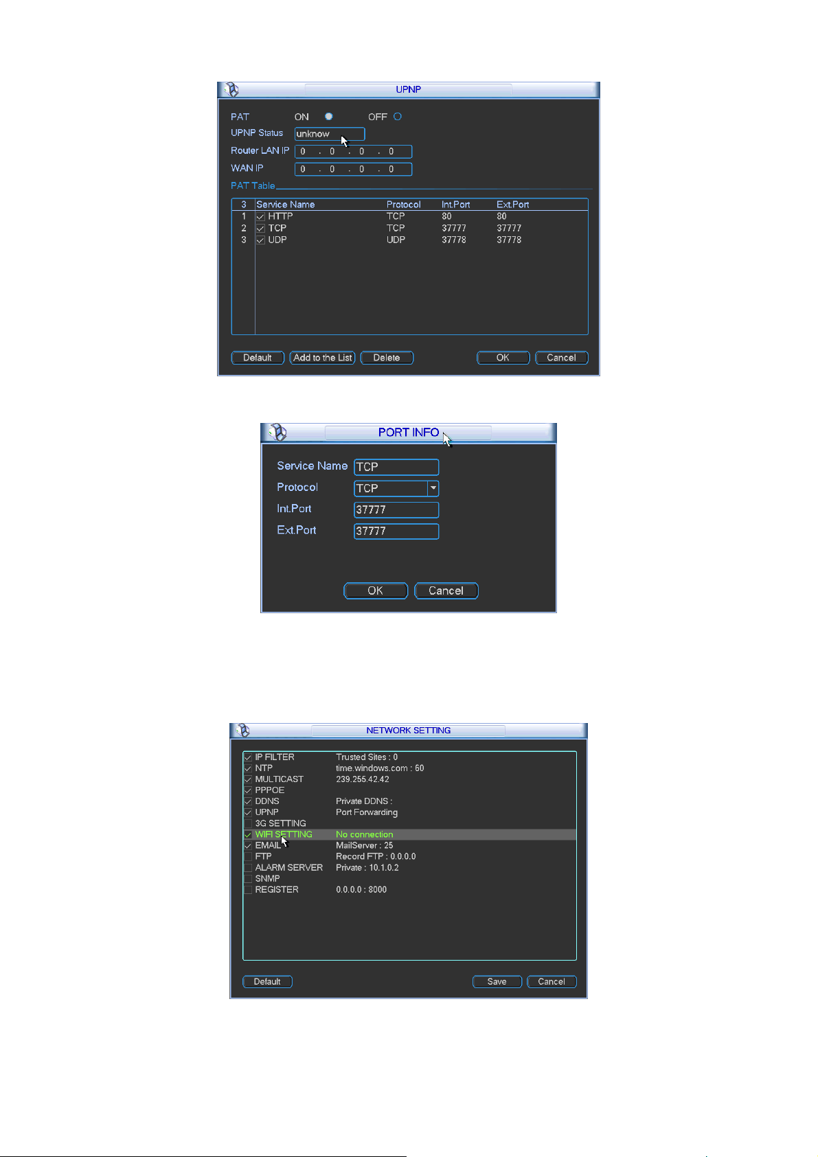
Figure 4-40
Figure 4-41
4.6.5.8 WIFI Setting
You can view the WIFI connection status in the Network Setting interface. See Figure 4-42.
You can view current connection status and IP address if there is a connection.
Figure 4-42
The WIFI interface is shown as below. See Figure 4-43.
53
Page 63

z Auto connect WIFI: Check the box here, system automatically connects to the previous WIFI
hotspot.
z Refresh: You can click it to search the hotspot list again. It can automatically add the
information such as the password if you have set it before.
z Disconnect: Here you can click it to turn off the connection.
z Connect: Here you can click it to connect to the hotspot. System needs to turn off current
connection and then connect to a new hotspot if there is connection of you selected one. See
Figure 4-44.
Figure 4-43
Figure 4-44
After successfully connection, you can see the following interface. You can see it is connected
now. See Figure 4-45.
54
Page 64

Figure 4-45
z WIFI working status: Here you can view current connection status.
Please note:
z After successful connection, you can see WIFI connection icon at the top right corner of the
preview interface.
z When the hotspot verification type is WEP, system displays as AUTO since the device can
not detect its encryption type.
z System does not support verification type WPA and WPA2. The display may become
abnormal for the verification type and encryption type.
After device successfully connected to the WIFI, you can view the hotspot name, IP address,
subnet mask, default gateway and etc. See Figure 4-46.
Figure 4-46
4.6.5.9 Email
The email interface is shown as below. See Figure 4-47.
z SMTP server: Please input your email SMTP server IP here.
z Port: Please input corresponding port value here.
z User name: Please input the user name to login the sender email box.
z Password: Please input the corresponding password here.
z Sender: Please input sender email box here.
55
Page 65

z Title: Please input email subject here. System support English character and Arabic number.
Max 32-digit.
z Receiver: Please input receiver email address here. System max supports 3 email boxes.
z SSL enable: System supports SSL encryption box.
z Interval: The send interval ranges from 0 to 3600 seconds. 0 means there is no interval.
z Health email enable: Please check the box here to enable this function. This function allows
the system to send out the test email to check the connection is OK or not.
z Interval: Please check the above box to enable this function and then set the corresponding
interval. System can send out the email regularly as you set here. Click the Test button, you
can see the corresponding dialogue box to see the email connection is OK or not. See
Figure 4-48.
Please note system will not send out the email immediately when the alarm occurs. When the
alarm, motion detection or the abnormity event activates the email, system sends out the email
according to the interval you specified here. This function is very useful when there are too many
emails activated by the abnormity events, which may result in heavy load for the email server.
Figure 4-47
Figure 4-48
4.6.5.10 FTP
You need to download or buy FTP service tool (such as Ser-U FTP SERVER) to establish FTP
service.
Please install Ser-U FTP SERVER first. From “start” -> “program” -> Serv-U FTP Server -> Serv-U
Administator. Now you can set user password and FTP folder. Please note you need to grant write
right to FTP upload user. See Figure 4-49.
56
Page 66
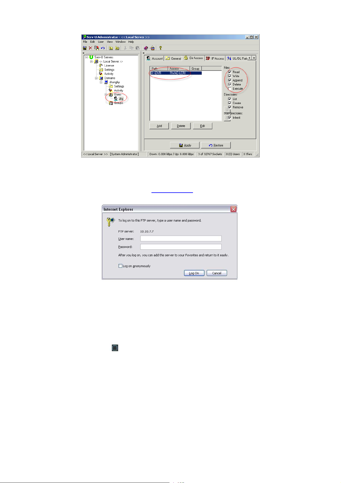
Figure 4-49
You can use a PC or FTP login tool to test setup is right or not.
For example, you can login user ZHY to
H140H140H140HTUFTP://10.10.7.7UTH and then test it can modify or delete
folder or not. See Figure 4-50.
Figure 4-50
System also supports upload multiple NVRs to one FTP server. You can create multiple folders
under this FTP.
In Figure 4-33, select FTP and then double click mouse. You can see the following interface. See
Figure 4-51.
Please highlight the icon
in front of Enable to activate FTP function.
Here you can input FTP server address, port and remote directory. When remote directory is null,
system automatically create folders according to the IP, time and channel.
User name and password is the account information for you to login the FTP.
File length is upload file length. When setup is larger than the actual file length, system will upload
the whole file. When setup here is smaller than the actual file length, system only uploads the set
length and auto ignore the left section. When interval value is 0, system uploads all corresponding
files.
After completed channel and weekday setup, you can set two periods for one each channel.
Click the Test button, you can see the corresponding dialogue box to see the FTP connection is
OK or not. See Figure 4-52.
57
Page 67

Figure 4-51
Figure 4-52
4.6.5.11 Alarm center
Interface is pre-reserved for the users to develop this function.
4.6.5.12 SNMP
SNMP is an abbreviation of Simple Network Management Protocol. It provides the basic network
management frame of the network management system. The SNMP widely used in many
environments. It is used in many network device, software and system.
You can set in the following interface. See Figure 4-53.
Figure 4-53
58
Page 68

Please enable the SNMP function. Use the corresponding software tool (MIB Builder and
MG-SOFT MIB Browser. You still need two MIB file: BASE-SNMP-MIB, NVR-SNMP-MIB) to
connect to the device. You can get the device corresponding configuration information after
successfully connection.
Please follow the steps listed below to configure.
z In Figure 4-53, check the box to enable the SNMP function. Input the IP address of the PC
than is running the software in the Trap address. You can use default setup for the rest items.
z Compile the above mentioned two MIB file via the software MIB Builder.
z Run MG-SOFT MIB Browser to load the file from the previous step to the software.
z Input the device IP you want to manage in the MG-SOFT MIB Browser. Please set the
corresponding version for your future reference.
z Open the tree list on the MG-SOFT MIB Browser; you can get the device configuration. Here
you can see the device has how many video channels, audio channels, application version
and etc.
4.6.5.13 Auto register
This function allows the device to auto register to the proxy you specified. In this way, you can use
the client-end to access the NVR and etc via the proxy. Here the proxy has a switch function. In
the network service, device supports the server address of IPv4 or domain.
Please follow the steps listed below to use this function.
Please set proxy server address, port, and sub-device name at the device-end. Please enable the
auto register function, the device can auto register to the proxy server.
1) The setup interface is shown as in Figure 4-54.
Important
Do not input network default port such as TCP port number.
Figure 4-54
2) The proxy server software developed from the SDK. Please open the software and input the
global setup. Please make sure the auto connection port here is the same as the port you set in
the previous step.
3) Now you can add device. Please do not input default port number such as the TCP port in the
mapping port number. The device ID here shall be the same with the ID you input in Figure 4-54.
Click Add button to complete the setup.
59
Page 69

4) Now you can boot up the proxy server. When you see the network status is Y, it means your
registration is OK. You can view the proxy server when the device is online.
Important
The server IP address can also be domain. But you need to register a domain name before you
run proxy device server.
4.6.6 Alarm
In the main menu, from Setting to Alarm, you can see alarm setup interface. See Figure 4-55.
z Alarm in: Here is for you to select channel number.
z Event type: There are four types. Local input/network input/IPC external/IPC offline alarm.
Local input alarm: The alarm signal system detects from the alarm input port.
Network input alarm: It is the alarm signal from the network.
IPC external alarm: It is the on-off alarm signal from the front-end device and can
activate the local NVR.
IPC offline alarm: Once you select this item, system can generate an alarm when the
front-end IPC disconnects with the local NVR. The alarm can activate record, PTZ, snap
and etc. The alarm can last until the IPC and the NVR connection resumes.
z Enable: Please you need to highlight this button to enable current function.
z Type: normal open or normal close.
z Period: It is to set local alarm period. System only enables local alarm in the specified period.
Click the Set button; you can select the business day and the non-business day. Please note
for the work day/free day setup and the specific work day setup, system just saves the latest
setup. For example, the work day ranges from 8:30-17:30 Monday to Friday, and then you set
the period 7:10-18:00 for Monday. So, the arm period of the Monday ranges from 7:10 to
18:00. Please highlight the corresponding button to enable this function.
z PTZ activation: When an alarm occurred, system can activate the PTZ operation. The PTZ
activation lasts an anti-dither period.
In the Pan/Tilt/Zoom interface (Main menu->Setting-> Pan/Tilt/Zoom), please set video
channel, speed dome protocol and etc.
Select the channel of current speed dome as current monitor video and the right click
mouse to select Pan/Tilt/Zoom item. Now you can set preset, tour pattern.
In Figure 4-56, click “select” button, you can see an interface is shown as in Figure 4-57.
Here you can set the activation operation such as preset tour, pattern and enable.
z Anti-dither: Here you can set anti-dither time. The value ranges from 5 to 600s. The
anti-dither time refers to the alarm signal lasts time. It can be seem as the alarm signal
activation stays such as the buzzer, tour, PTZ activation, snapshot, channel record. The stay
time here does not include the latch time. During the alarm process, the alarm signal can
begin an anti-dither time if system detects the local alarm again. The screen prompt, alarm
upload, email and etc will not be activated. For example, if you set the anti-dither time as 10
second, you can see the each activation may last 10s if the local alarm is activated. During
the process, if system detects another local alarm signal at the fifth second, the buzzer, tour,
PTZ activation, snapshot, record channel will begin another 10s while the screen prompt,
alarm upload, email will not be activated again. After 10s, if system detects another alarm
signal, it can generate an alarm since the anti-dither time is out.
60
Page 70

z Alarm output: The number here is the device alarm output port. You can select the
corresponding ports(s) so that system can activate the corresponding alarm device(s) when
an alarm occurred.
z Latch: When the anti-dither time ended, the channel alarm you select in the alarm output may
last the specified period. The value ranges from 1 to 300 seconds. This function is not for
other alarm activation operations. The latch is still valid even you disable the alarm event
function directly.
z Show message: System can pop up a message to alarm you in the local host screen if you
enabled this function.
z Alarm upload: System can upload the alarm signal to the network (including alarm centre
and the WEB) if you enabled current function. System only uploads the alarm channel
status. You can go to the WEB and then go to the Alarm interface to set alarm event and
alarm operation. Please go to the Network interface to set alarm centre information.
z Send email: System can send out the alarm signal via the email to alert you when alarm
occurs. Once you enable the snap function, system can also send out an image as the
attachment. Please go to the Main Menu->Setting ->Network->Email interface to set.
z Record channel: you can select proper channel to record alarm video (Multiple choices).
You need to set alarm record mode as Schedule in Record interface (Main
Menu->Advanced->Record). Please note the manual record has the highest priority.
System record all the time no matter there is an alarm or not if you select Manual mode.
Now you can go to the Schedule interface (Main Menu->Setting->Schedule) to set the
record type, corresponding channel number, week and date. You can select the record
type:Regular/MD/Alarm/MD&Alarm. Please note, you can not select the MD&Alarm and
MD(or Alarm) at the same time.
Now you can go to the Encode interface to select the alarm record and set the encode
parameter (Main Menu->Setting->Encode).
Finally, you can set the alarm input as the local alarm and then select the record channel.
The select channel begins alarm record when an alarm occurred. Please note system
begins the alarm record instead of the MD record if the local alarm and MD event
occurred at the same time.
z Tour: Here you can enable tour function when an alarm occurs. System supports 1/8-window
tour. Please go to chapter 4.6.9 Display for tour interval setup. Please note the tour setup
here has higher priority than the tour setup you set in the Display interface. Once there two
tours are both enabled, system can enable the alarm tour as you set here when an alarm
occurred. If there is no alarm, system implements the tour setup in the Display interface.
z Snapshot: You can enable this function to snapshoot image when an alarm occurs.
z Buzzer: Highlight the icon to enable this function. The buzzer beeps when an alarm occurs.
Please highlight icon
please click save button, system goes back to the previous menu.
to select the corresponding function. After setting all the setups
61
Page 71
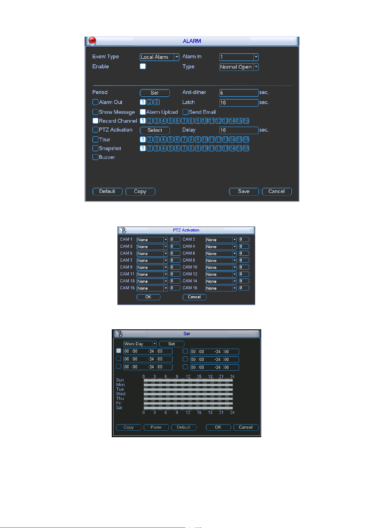
Figure 4-55
Figure 4-56
Figure 4-57
62
Page 72

Figure 4-58
For the 32-channel series product, the alarm interface and PTZ setup is shown as below. See
Figure 4-59 and Figure 4-60.
Figure 4-59
Figure 4-60
4.6.7 Detect
Go to Detect Menu
In the main menu, from Setting to Detect, you can see motion detect interface. See Figure
4-61.There is three detection types: motion detection, video loss, camera masking.
z The video loss has no detection region and sensitivity setup and camera masking has no
63
Page 73

detection region setup.
z You can see motion detect icon if current channel has enabled motion detect alarm.
z You can drag you mouse to set motion detect region without Fn button. Please click OK
button to save current region setup. Right click mouse to exit current interface.
4.6.7.1 Motion Detect
Detection menu is shown as below. See Figure 4-61.
z Event type: From the dropdown list you can select motion detection type.
z Channel: Select a channel from the dropdown list to set motion detect function.
z Enable: Check the box here to enable motion detect function.
z Region: Click select button, the interface is shown as in Figure 4-62. Here you can set
motion detection zone. There are 396(PAL)/330(NTSC) small zones. The green zone is
current cursor position. Grey zone is the motion detection zone. Black zone is the disarmed
zone. You can click Fn button to switch between the arm mode and disarm mode. In arm
mode, you can click the direction buttons to move the green rectangle to set the motion
detection zone. After you completed the setup, please click ENTER button to exit current
setup. Do remember click save button to save current setup. If you click ESC button to exit
the region setup interface system will not save your zone setup.
z Sensitivity: System supports 6 levels. The sixth level has the highest sensitivity.
z Period: Click set button, you can see an interface is shown as in Figure 4-64. Here you can
set for business day and non-business day. In Figure 4-64 click set button, you can see an
interface is shown as in Figure 4-65. Here you can set your own setup for business day and
non-business day.
z Alarm output: when an alarm occurs, system enables peripheral alarm devices.
z Latch: when motion detection complete, system auto delays detecting for a specified time.
The value ranges from 1-300(Unit: second)
z Show message: System can pop up a message to alarm you in the local host screen if you
enabled this function.
z Alarm upload: System can upload the alarm signal to the network (including alarm centre)
if you enabled current function.
z Send email: System can send out email to alert you when an alarm occurs.
z Record channel: Select the channel to activate recording function once an alarm occurred.
Please make sure you have set MD record in encode interface(Main
Menu->Setting->Schedule) and schedule record in manual record interface(Main
Menu->Advanced->Manual Record)
z PTZ activation: Here you can set PTZ movement when an alarm occurs. System can go to a
preset, when there is an alarm. Click “select” button, you can see an interface is shown as in
Figure 4-63.
z Record Delay: System can delay the record for specified time after alarm ended. The value
ranges from 10s to 300s.
z Tour: Here you can enable tour function when an alarm occurs. System one-window tour.
Please go to chapter 5.3.9 Display for tour interval setup.
z Snapshot: You can enable this function to snapshoot image when motion detect alarm
occurs.
Please highlight icon to select the corresponding function. After all the setups please click
64
Page 74
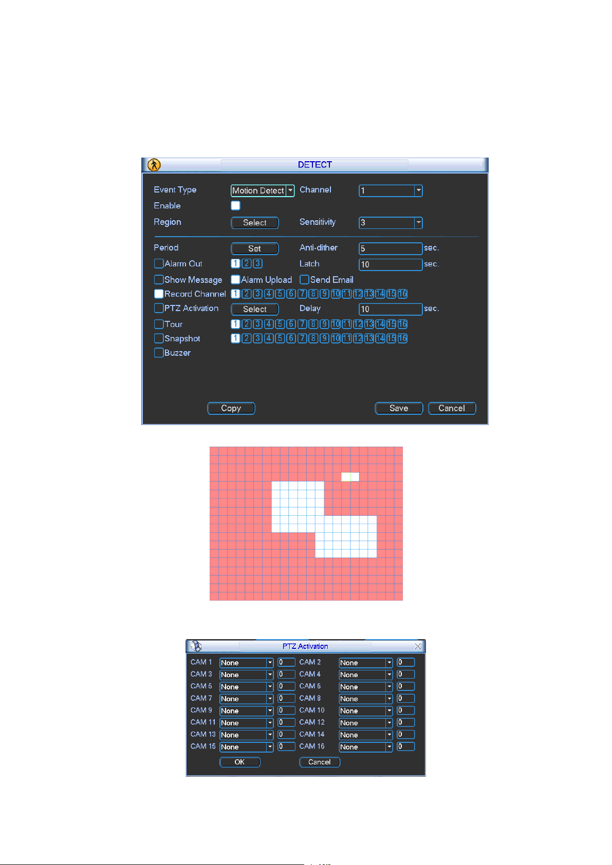
save button, system goes back to the previous menu.
Note:
In motion detection mode, you can not use copy/paste to set channel setup since the video in
each channel may not be the same.
In Figure 4-62, you can left click mouse and then drag it to set a region for motion detection. Click
Fn to switch between arm/withdraw motion detection. After setting, click enter button to exit.
Figure 4-61
Figure 4-62
Figure 4-63
65
Page 75
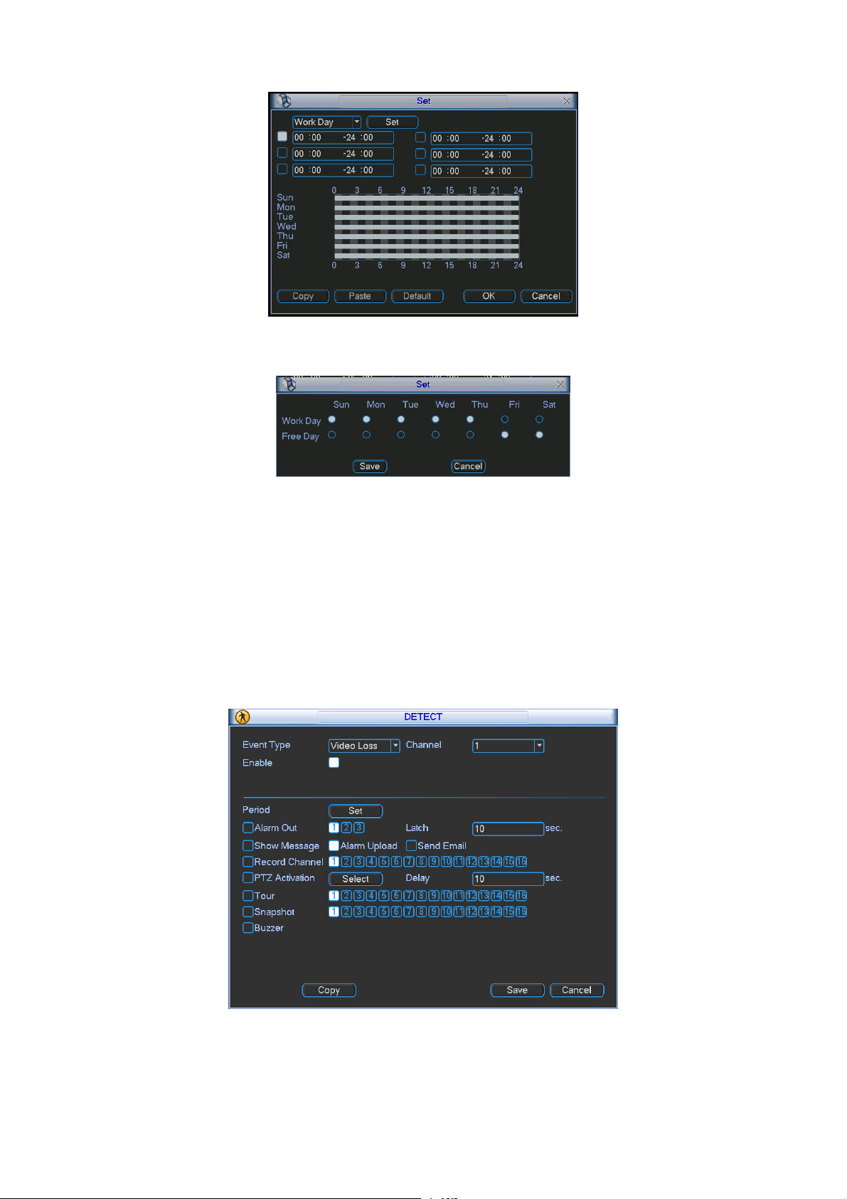
Figure 4-64
Figure 4-65
4.6.7.2 Video Loss
In Figure 4-61, select video loss from the type list. You can see the interface is shown as in
Figure 4-66.This function allows you to be informed when video loss phenomenon occurred.
You can enable alarm output channel and then enable show message function.
You can refer to chapter 4.6.7.1Motion detect for detailed information.
Tips:
You can enable preset/tour/pattern activation operation when video loss occurs.
Figure 4-66
4.6.7.3 Camera Masking
When someone viciously masks the lens, or the output video is in one-color due to the
66
Page 76

environments light change, the system can alert you to guarantee video continuity. Camera
masking interface is shown as in Figure 4-67. You can enable alarm output channel and then
enable show message function. You can refer to chapter 4.6.7.1Motion detect for detailed
information.
Tips:
You can enable preset/tour/pattern activation operation when video loss occurs.
Note:
In Detect interface, copy/paste function is only valid for the same type, which means you can
not copy a channel setup in video loss mode to camera masking mode.
Figure 4-67
4.6.8 PTZ
Note: All the operations here are based on PELCOD protocol. For other protocols, there might
be a little difference.
Cable Connection
Please follow the procedures below to go on cable connection
z Connect the dome RS485 port to NVR 485 port.
z Connect dome video output cable to NVR video input port.
z Connect power adapter to the dome.
PTZ Setup
Note: The camera video should be in the current screen. Before setup, please check the
following connections are right:
z PTZ and decoder connection is right. Decoder address setup is right.
z Decoder A (B) line connects with NVR A (B) line.
Boot up the NVR, input user name and password.
In the main menu, click setting, and then click Pan/Tilt Control button. The interface is shown
as in Figure 4-68. Here you can set the following items:
z Channel: Select the current camera channel.
z PTZ type: There are two types: local/remote.
z Protocol: Select corresponding PTZ protocol(such as PELCOD)
67
Page 77

z Address: Default address is 1.
z Baud rate: Select corresponding baud rate. Default value is 9600.
z Data bit: Select corresponding data bits. Default value is 8.
z Stop bit: Select corresponding stop bits. Default value is 1.
z Parity: There are three options: odd/even/none. Default setup is none.
Figure 4-68
If you are connecting to network PTZ, the PTZ type shall be remote. See Figure 4-69.
Figure 4-69
After completing all the setting please click save button.
In one window display mode, right click mouse (click “Fn” Button in the front panel or click “Fn”
key in the remote control).
Click Pan/Tilt/Zoom, the interface is shown as below. See Figure 4-70.
Here you can set the following items:
z Step: value ranges fro 1 to 8.
z Zoom
z Focus
z Iris
68
Page 78
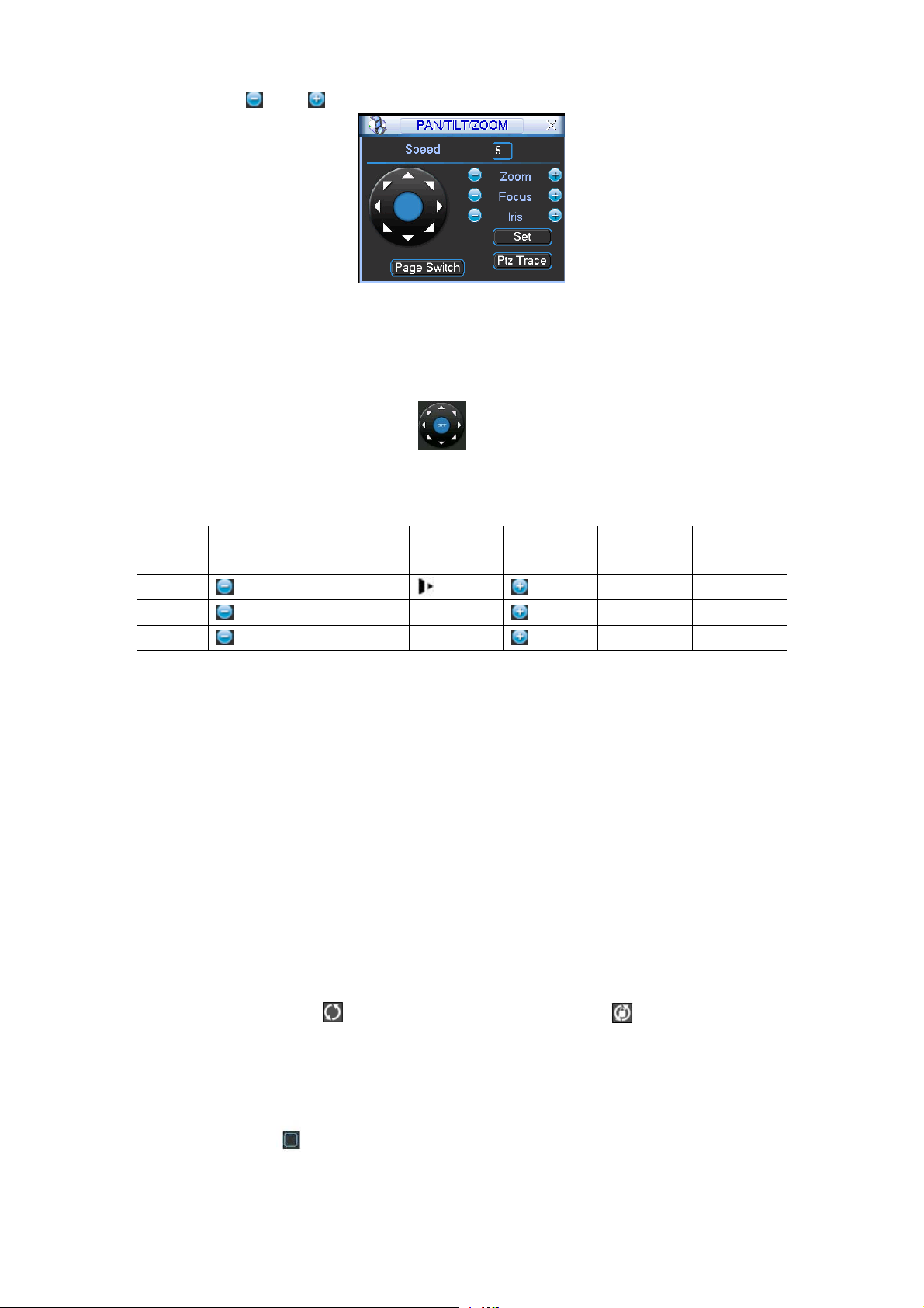
Please click icon and to adjust zoom, focus and iris.
Figure 4-70
In Figure 4-70, please click direction arrows to adjust PTZ position. There are total 8 direction
arrows.
Figure 4-71
Here is a sheet for you reference.
Name Function
key
Zoom
Focus
Iris
function Shortcut
key
Wide
Near
Close
│_
W
Function
key
function Shortcut
Key
Far
Far
Open
►
│
f
4.6.9 Display
Display setup interface is shown as below. See Figure 4-72.
z Transparency: Here is for you to adjust transparency. The value ranges from 128 to 255.
z Channel name: Here is for you to modify channel name. System max support 25-digit (The
value may vary due to different series). Please note all your modification here only applies to
NVR local end. You need to open web or client end to refresh channel name.
z Time display: You can select to display time or not when system is playback.
z Channel display: You can select to channel name or not when system is playback.
z Resolution: There are four options: 1280×1024(default),1280×720,1024×768,800×600.
Please note the system needs to reboot to activate current setup.
z Enable tour: Activate tour function.
z Interval: System supports 1/4/8/9/16-window tour. Input proper interval value here. The value
ranges from 5-120 seconds. In tour process, you can use mouse or click Shift to turn on
window switch function.
Stands for opening switch function, stands for closing
switch function.
z Monitor tour type: System support 1/8-window tour.
z Alarm tour type: System support 1/8-window tour.
Please highlight icon
to select the corresponding function.
After completing all the setups please click save button, system goes back to the previous menu.
69
Page 79

Figure 4-72
In Figure 4-72, click modify button after channel. You can see an interface shown as in Figure
4-73. Please note all your modification here applies to local end only. You need to refresh web or
client-end to get the latest channel name. System max support 25-digital character.
Figure 4-73
4.6.10 Default
Click default icon, system pops up a dialogue box. You can highlight to restore default factory
setup.
z Select all
z General
z Encode
z Schedule
z RS232
z Network
z Alarm
z Detect
z Pan/tilt/zoom
70
Page 80

z Display
z Channel name
Please highlight icon
After all the setups please click OK button, system goes back to the previous menu.
Warning!
System menu color, language, time display mode, video format, IP address, user account will not
maintain previous setup after default operation!
to select the corresponding function.
4.6.11 Remote Device
Important
Do not connect the switch to the PoE port, otherwise the connection may fail!
4.6.11.1 UPNP
Please connect the IPC to the PoE port of the device rear panel (Figure 4-74), system can auto
connect to the network camera. Please note the following figure is for reference only.
Figure 4-74
4.6.11.2 Built-in Switch Setup
The built-in switch function is for product of PoE port.
From Network->Network Server->Switch, you can set switch IP address, subnet mask, gateway
and etc. See Figure 4-75.
Figure 4-75
4.6.11.3 Remote Device
In the main menu, click the Remote Device icon to go to the corresponding interface. See Figure
4-76.
71
Page 81

Figure 4-76
The remote device interface is shown as in Figure 4-77.
z IP search: Click it to search IP address.
z Add: Click it to connect to the selected device and add it to the Added device list. Support
Batch add.
z Show filter: You can use it to display the specified devices from the added device.
z IPC config: Double click the
interface. See Figure 4-78.
Gain mode: It is to set video noise. Check Auto, system automatically sets video gain.
Check Manual, you can set gain threshold, brightness and etc.
Gain threshold: Here is for you to set gain value. The different series product has
different default values. The lower the value is, the lower the noise is. But the video
brightness may become too dark under the low illumination. If the value is high, it can
enhance the video brightness under the low illumination, but the video noise may
become high.
BLC: Check the box here to enable backlight compensation function. System can
automatically expose according to environment so that you can view the darkest section
of the video.
Day/Night mode: Here is to set video color or black and white mode.
a) Color: Camera only outputs color video.
b) Auto: Camera auto selects color or black and white video according to device feature
(Video whole brightness or there is any IR light or not.).
c) Black and white: Camera only outputs black and white video.
Exposure mode:
a) Auto: The video whole brightness can adjust automatically within the normal
exposure threshold according to different environments. The lower the gain value is,
the smaller the noise is.
b) Manual: It is to display manual exposure value.
z Delete: Please select one device in the Added device list and then click it to remove.
z Manual add: Click it to add the IPC manually. The port number is 37777. The default user
name is admin and password is admin.
on the IPC config column, you can go to the IPC setup
72
Page 82

Figure 4-77
Figure 4-78
Click the Manual Add button; you can go to the following interface. See Figure 4-79.
This series product max supports 32-channel standard definition video/high definition
non-real-time video and the transmission rate is 1Mbps per channel. It can also max supports
4-channel high definition video and the transmission rate is 8Mbps. The delay time of each
channel is below 500ms.
Model System Performance
4-ch series Max support 4-channel video.
73
Page 83

Total resources:400/480fps@D1,200/240fps@720P.100/120@1080P.
8-ch series Max support 8-channel video.
Total resources:400/480fps@D1,200/240fps@720P.100/120@1080P.
16-ch series Max support 16-channel video.
Total resources:400/480fps@D1,200/240fps@720P.100/120@1080P.
32-ch series Max support 32-channel standard definition video.
Support 8-channel 1080p/5Mbps (extra stream D1/1Mbps), 16-channel
720p/2Mbps (extra CIF/640kbps), 32-channel D1/1Mbps.
This series product supports the IPC from many popular manufactures such as Sony, Hitachi,
dynacolor, Axis, Samsung, arecont, Dahua, onvif and custom type. You can just input URL
address, user name, and password to login the front-end device.
In the following interface, you can see there are three connection modes: auto, TCP (default),
UDP.
Figure 4-79
4.6.11.4 Short-cut Menu
In the preview interface, for the channel of no IPC connection, you can click the icon “+” in the
centre of the interface to quickly go to the Remote Device interface. See Figure 4-80 and Figure
4-81.
74
Page 84

Figure 4-80
Figure 4-81
4.7 Advanced
Double click advanced icon in the main window, the interface is shown as below. See Figure
4-82.There are total eight function keys: HDD management, alarm output, abnormity, manual
record, account, auto maintenance, TV adjust and video matrix.
75
Page 85

Figure 4-82
4.7.1 HDD Management
Here is for you to view and implement hard disk management. See Figure 4-83.
You can see current HDD type, status, capacity and record time. When HDD is working properly,
system is shown as O. When HDD error occurred, system is shown as X.
z Alarm set: Click alarm set button, the interface is shown as below. See Figure 4-84. (This
interface is just like the abnormality setup). Please refer to chapter 4.7.2 for detailed
information.
z HDD operation: You can select HDD mode from the dropdown list such as read-only or you
can erase all data in the HDD. Please note system needs to reboot to get all the modification
activated.
Figure 4-83
76
Page 86

Figure 4-84
For the HDD group setup operation, please note:
z Each channel’s records can be stored into the specified HDD Group.
z Each HDD Group is corresponding to several hard disks, while one hard disk is only
included in one HDD Group.
z Each channel is only corresponding with one HDD Group, while one HDD Group can
store records from several channels.
z HDD Group is only available for read-write HDD and self-defined disks, other types of
hard disks cannot be set as HDD Group.
Important:
z eSATA also supports this function, you can manage e-SATA hard disk as local hard disk.
z Current series software version can only set the HDD group operation of the read-write HDDs.
It is not for the redundancy HDD.
HDD Setting
Click the button “HDD Settings” at the top right corner of the Figure 4-83, system will pop up an
interface as below. See Figure 4-85.
The number of hard disk from 1 to 2 is shown in the “HDD No.” column (It is to show the max HDD
amount you can install). If serial number is highlighted, it means this interface have access to the
hard disk, otherwise it does not have access to the hard disk.
The “HDD Group” column lists the HDD Group number of current hard disk. You can select HDD
group name from the dropdown list and then click Save button.
Please note, one HDD is corresponding to one group, while one group can have many HDDs.
The HDD group No. is corresponding HDD port, the HDD group No. may vary if you change the
HDD.
Important
Once you change the HDD Group settings, system will pack the records and snapshots, and then
reboot.
77
Page 87

Figure 4-85
Channels Setting
Click the button named with “Channels Settings” at the top right corner of the Figure 4-83, system
will pop up an interface shown as in Figure 4-86.
You can set HDDs for main stream, extra stream and snap pictures respectively. The main stream
and extra stream of one channel can be saved to different groups.
Channel: It is to display the actual channel number of current NVR.
HDD Group: It is the SN of the HDD group management. For example, if you set two HDD groups
such as Group 1 and Group 2, you can see there are two options (1/2) of the HDD group
dropdown list.
Important
z Please make sure you have set HDD group for each channel, otherwise you can not save
current setup!
z Once you change the HDD Group settings, system will pack the records and then reboot!
Tips
There is an easy way for you to test whether the records from the corresponding channel is saved
in the specified HDD. You can remove the HDD and then check the channel can record or not.
You can see the channel does not record and you can not search the previous record now.
Figure 4-86
4.7.2 Abnormality
Abnormality interface is shown as in Figure 4-87.
78
Page 88

z Event type: There are several options for you such as disk error, no disk, disconnection,
IP conflict and etc.
z Alarm output: Please select alarm activation output port (multiple choices).
z Latch: Here you can set corresponding delaying time. The value ranges from 10s-300s.
System automatically delays specified seconds in turning off alarm and activated output after
external alarm cancelled.
z Show message: system can pop up the message in the local screen to alert you when an
alarm occurs.
z Alarm upload: System can upload the alarm signal to the network (including alarm centre)
if you enabled current function.
z Send email: System can send out email to alert you when an alarm occurs.
z Buzzer: Highlight the icon to enable this function. The buzzer beeps when an alarm occurs.
Figure 4-87
4.7.3 Alarm Output
Here is for you to set proper alarm output.
Please highlight icon
After all the setups please click OK button, system goes back to the previous menu. See Figure
4-88.
to select the corresponding alarm output.
4.7.4 Manual Record
Figure 4-88
79
Page 89

Note:
You need to have proper rights to implement the following operations. Please make sure the
HDD has been properly installed.
4.7.4.1 Manual record menu
Right click mouse or in the main menu, Advanced->Manual Record.
Manual record menu is shown as in Figure 4-89.
4.7.4.2 Basic operation
There are three statuses: schedule/manual/stop. Please highlight icon “○” to select
corresponding channel.
z Manual: The highest priority. After manual setup, all selected channels will begin ordinary
recording.
z Schedule: Channel records as you have set in recording setup (Main
Menu->Setting->Schedule)
z Stop: All channels stop recording.
Figure 4-89
4.7.4.3 Enable/disable record
Please check current channel status: “○” means it is not in recording status, “●” means it is in
recording status.
You can use mouse or direction key to highlight channel number. See Figure 4-90.
Figure 4-90
4.7.4.4 Enable all channel recording
Highlight ○ below All, you can enable all channel recording.
80
Page 90

z All channel schedule record
Please highlight “ALL” after “Schedule”. See Figure 4-91.
When system is in schedule recording, all channels will record as you have previously set
(Main menu->Setting->Schedule).
The corresponding indication light in front panel will turn on.
Figure 4-91
z All channel manual record
Please highlight “ALL” after “Manual.” See Figure 4-92.
When system is in manual recording, all scheduled set up you have set in will be null ((Main
menu->Setting->Schedule)).
You can see indication light in front panel turns on, system begins manual record now.
Figure 4-92
4.7.4.5 Stop all channel recording
Please highlight “ALL” after “Stop”. See Figure 4-93.
System stops all channel recording no matter what mode you have set in the menu (Main
menu->Setting->Schedule)
81
Page 91

Figure 4-93
4.7.5 Account
Here is for you to implement account management. See Figure 4-94. Here you can:
z Add new user
z Modify user
z Add group
z Modify group
z Modify password.
For account management please note:
z For the user account name and the user group, the string max length is 6-byte. The
backspace in front of or at the back of the string is invalid. There can be backspace in the
middle. The string includes the valid character, letter, number, underline, subtraction sign,
and dot.
z System account adopts two-level management: group and user. No limit to group or user
amount.
z For group or user management, there are two levels: admin and user.
z The user name and group name can consist of eight bytes. One name can only be used once.
There are four default users: admin/888888/666666 and hidden user “default”. Except user
6666, other users have administrator right.
z Hidden user “default” is for system interior use only and can not be deleted. When there is no
login user, hidden user “default” automatically login. You can set some rights such as monitor
for this user so that you can view some channel view without login.
z One user should belong to one group. User right can not exceed group right.
z About reusable function: this function allows multiple users use the same account to login.
After all the setups please click save button, system goes back to the previous menu.
82
Page 92
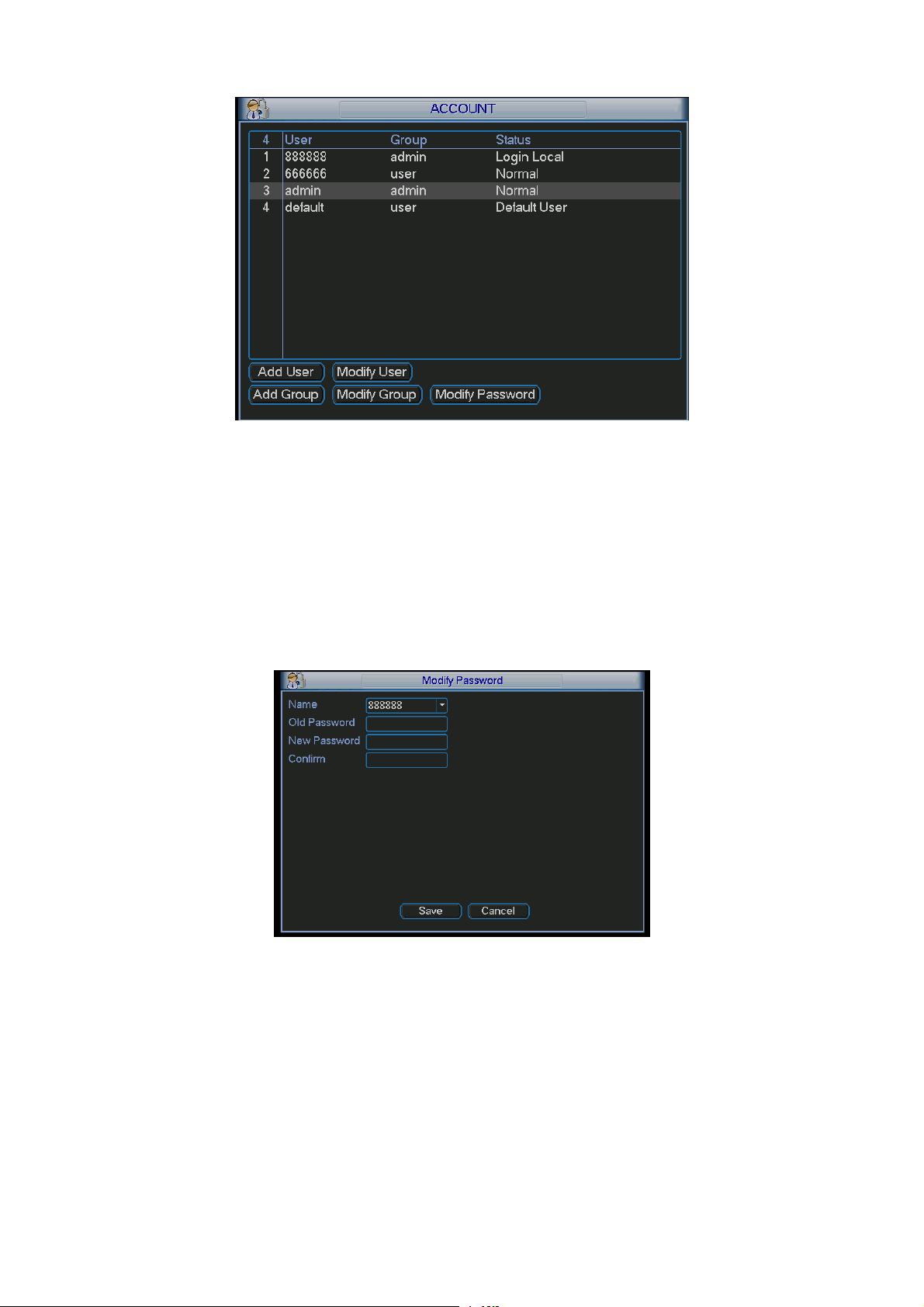
Figure 4-94
4.7.5.1 Modify Password
Click password button, the interface is shown as in Figure 4-95.
Here you can modify account password.
Please select the account from the dropdown list, input the old password and then input the new
password twice. Click the Save button to confirm current modification.
For the users of user account right, it can modify password of other users.
Figure 4-95
4.7.5.2 Add/Modify Group
Click add group button, the interface is shown as below. See Figure 4-96.
Here you can input group name and then input some memo information if necessary.
There are total 60 rights such as control panel, shut down, real-time monitor, playback, record,
record file backup, PTZ, user account, system information view, alarm input/output setup, system
setup, log view, clear log, upgrade system, control device and etc.
The modify group interface is similar to the Figure 4-96.
83
Page 93

Figure 4-96
4.7.5.3 Add/Modify User
Click add user button, the interface is shown as in Figure 4-97.
Please input the user name, password, select the group it belongs to from the dropdown list.
Then you can check the corresponding rights for current user.
For convenient user management, usually we recommend the general user right is lower than the
admin account.
The modify user interface is similar to Figure 4-97.
Figure 4-97
4.7.6 Auto Maintenance
Here you can set auto-reboot time and auto-delete old files setup. You can set to delete the files
for the specified days. See Figure 4-98.
You can select proper setup from dropdown list.
After all the setups please click save button, system goes back to the previous menu.
84
Page 94

Figure 4-98
4.7.7 Config Backup
The configuration file backup interface is shown as below. See Figure 4-99.
This function allows you to copy current system configuration to other devices. It also supports
import, create new folder, delete folder and etc function.
Figure 4-99
4.8 Shutdown
Double click shutdown button, system pops up a dialogue box for you to select. See Figure 4-100.
z Logout menu user: log out menu. You need to input password when you login the next time.
z Restart application: reboot device.
z Shutdown: system shuts down and turns off power.
z Restart system: system begins rebooting.
z Switch user: you can use another account to login.
If you shut down the device, there is a process bar for your reference, system waits for 3 seconds
and then shut down (You can not cancel).
Please note, sometimes you need to input the proper password to shut down the device.
85
Page 95

Figure 4-100
86
Page 96

5 Quick Configuration Tool
5.1 Overview
Quick configuration tool can search current IP address, modify IP address. At the same time, you
can use it to upgrade the device.
Please note the tool only applies to the IP addresses in the same segment.
5.2 Operation
Double click the “ConfigTools.exe” icon, you can see an interface is shown as in Figure 5-1.
In the device list interface, you can view device IP address, port number, subnet mask, default
gateway, MAC address and etc.
Figure 5-1
Select one IP address and then right click mouse, you can see an interface is shown as in Figure
5-2.
Figure 5-2
87
Page 97

Select the “Open Device Web” item; you can go to the corresponding web login interface. See
Figure 5-3.
Figure 5-3
If you want to modify the device IP address without logging in the device web interface, you can
go to the configuration tool main interface to set.
In the configuration tool search interface (Figure 5-1), please select a device IP address and then
double click it to open the login interface. Or you can select an IP address and then click the Login
button to go to the login interface. See Figure 5-4.
In Figure 5-4, you can view device IP address, user name, password and port. Please modify the
corresponding information to login.
Please note the port information here shall be identical with the port value you set in TCP port in
Web Network interface. Otherwise, you can not login the device.
If you are using device background upgrade port 3800 to login, other setups are all invalid.
Figure 5-4
After you logged in, the configuration tool main interface is shown as below. See Figure 5-5.
Please refer to the Quick Configuration T ool User's Manual included in the resources CD for detail
information.
88
Page 98

Figure 5-5
For detailed information and operation instruction of the quick configuration tool, please
refer to the Quick Configuration Tool User’s Manual included in the resources CD.
89
Page 99

6 Web Operation
6.1 General Introduction
The device web provides channel monitor menu tree, search, alarm setup, system setup, PTZ
control and monitor window.
Important
The following operation is based on 16-channel series device. For the 32-channel series
product, there is 32-channel option.
6.1.1 Preparation
Before log in, please make sure:
z Network connection is right
z NVR and PC network setup is right. Please refer to network setup(main
z menu->setting->network)
z Use order ping ***.***.***.***(* NVR IP address) to check connection is OK or not. Usually the
return TTL value should be less than 255.
z Open the IE and then input NVR IP address.
z System can automatically download latest web control and the new version can overwrite the
previous one.
z If you want to un-install the web control, please run uninstall webrec2.0.bat. Or you can go to
C:\Program Files\webrec to remove single folder. Please note, before you un-install, please
close all web pages, otherwise the un-installation might result in error.
z Current series product supports various browsers such as Safari, firebox browser, Google
browser. Device only support 1-channel monitor on the Apple PC.
About PoE address setup, operation and allocation.
1) Insert PoE
After you insert PoE, device may try to set a corresponding IP address of the Switch network
adapter. First, system tries to set via arp ping. It then uses DHCP if it finds the DHCP is enabled.
After successfully set IP address, system may use Switch to send out broadcast, system thinks
the connection is OK when there is any response. Now system is trying to login the newly found
IPC. Now please check the interface, you can see the corresponding digital channel is active now.
You can see a small PoE icon at the top left corner. You can see the PoE channel, PoE port
information and etc from the connection list of the remote device interface (Chapter 4.6.11). For
the IP search list, you need to click the IP search to display or refresh.
2) Remove PoE
After you removed PoE, you can see the corresponding digital channel becomes idle (disable).
On the remote device interface, it is removed from the connected list. For the IP search list, you
need to click the IP search to refresh.
3) After you insert PoE, system follows the principles listed below to map channel.
a) If it is your first time to insert PoE, system can map it to the first idle channel. After
map, the channel can memorize the MAC address of the IPC. It is a
<Channel>---<IPC mac> map. If current channel does not connect to other device,
system can memorize current MAC address, otherwise it can refresh to the newly
added device and memorize the <PoE port>---<Channel>.
90
Page 100

b) If it is your second time to insert the PoE, system can check the saved MAC address
according to <Channel>---<IPC mac> map to make sure current IPC has connected
or not. If system finds the previous information and the channel is idle, system can
map it to the previously used channel. Otherwise system goes to the next step.
c) Thirdly, according to the <PoE port>---<Channel> map, system can know the
previous mapping channel of current PoE port. System can select current channel if
it is free. Otherwise, it goes to the next step:
d) Fourthly, system goes to find the first idle channel it can get.
Generally speaking, once you insert PoE, system follow the steps listed above to find the channel
available.
4) When you insert PoE, all channels are in use now.
System can pop up a dialogue box for you to select a channel to overwrite. The title of the pop-up
interface is the name of the current operation PoE port. In this interface, All PoE channel become
grey and can not select.
6.1.2 Log in
Open the IE and then input the NVR IP address in the address column.
For example, if your NVR IP address is 192.168.1.108, then please input http:// 192.168.1.108 in
IE address column. See Figure 6-1.
Input IP
address here.
Figure 6-1 IE Interface
System pops up warning information to ask you whether install webrec.cab control or not. Please
click yes button.
If you can’t download the ActiveX file, please modify your settings as follows. See Figure 6-2.
91
 Loading...