

IC Plus Corp TP112 Datasheet
TP112
100Base-TX/FX Converter
Feature
n 100Base-TX IEEE 802.3u compatible
n Full and Half duplex with Auto-negotiation
n Fully integrated adaptive equalizers
n 125MHz clock generator and clock recovery
n Include transmit waveform shaping to reduce EMI and
filter
n Include baseline wander correction
n Support one TX interface and one Fiber module
interface(ECL interface).
n Support transmit, receive/link, full duplex LED
n Single 5 Voltage supply operation
n 128-pin PQFP
Typical Application
General Description
The TP112 is a single chip media converter for
100Base-TX to 100Base-FX. The TP112 support one
100Base-TX port over CAT5 twisted pair cable and one
ECL interface to connect with fiber module to apply in
100Base-TX/FX converter application. On the
100Base-TX side, The TP112 is directly connected to
external transformers
The chip performs data recovery, clock recovery,
adaptive equalization, auto negotiation, and baseline
wander correction function. The TP112 is compliant with
the IEEE 802.3u standard.
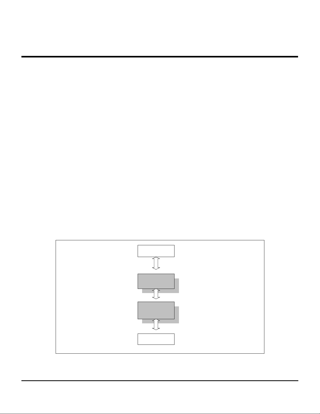
n 100Base-TX to 100Base-FX Converter
FX
Fiber Module
TP112
TX
1
TP112-DS-P02
Jan 5, 2000
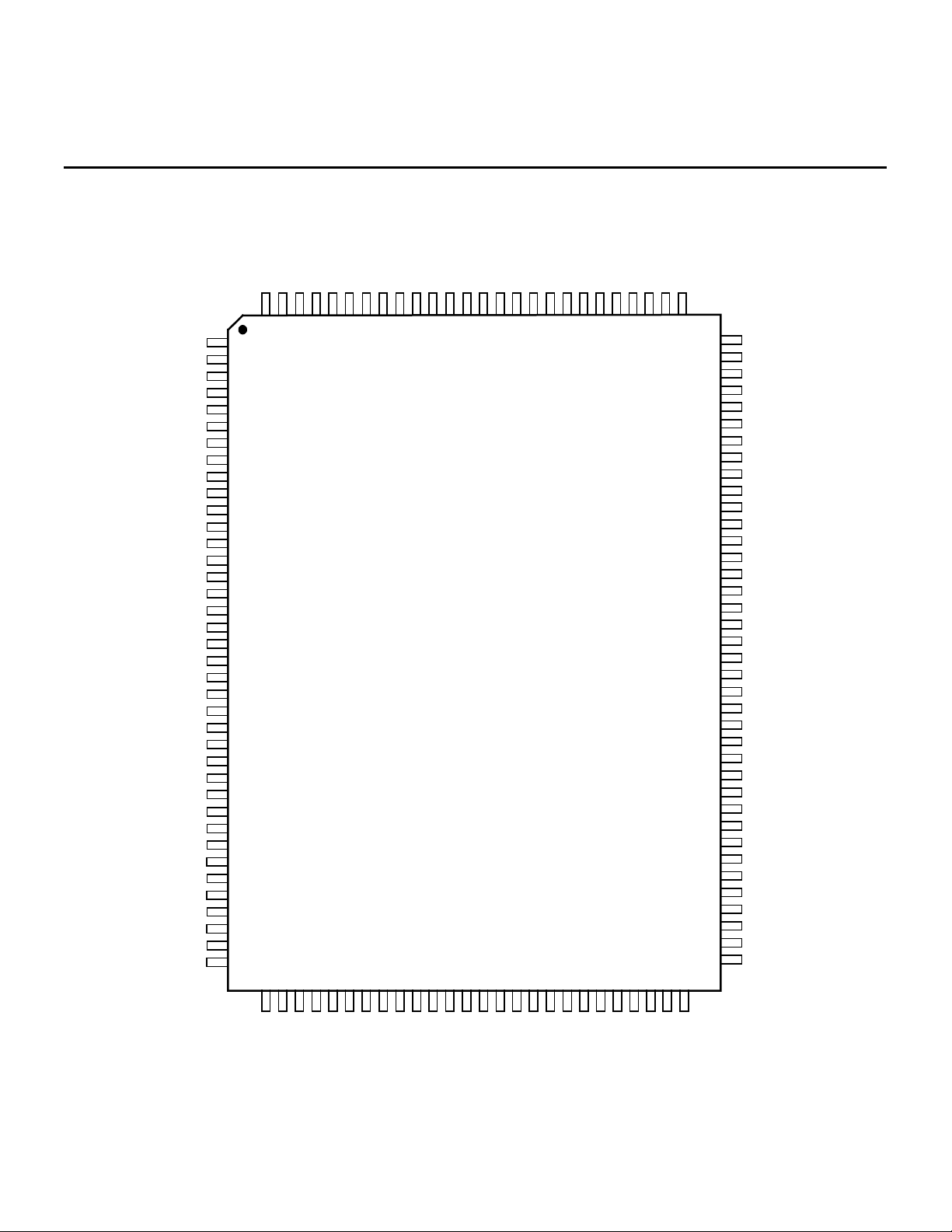
PIN Assignments
TP112
FXRDP
FXRDM
FXSD
AVCC
AVCC
NC
FXTDM
FXTDP
AGND
BGRES
BGGND
AVCC
DVCC
DGND
FORCEON
DVCC
DVCC
HALFONLY
TMODE
NC
NC
NC
DVCC
NC
DVCC
DVCC
FXTLED*
FXLRLED*
DGND
TXER1
TXD31
TXD21
TXD11
TXD01
TXCLK1
MDC
MDIO
NC
AGND
AGND
126
127
128
1
2
3
4
5
6
7
8
9
10
11
12
13
14
15
16
17
18
19
20
21
22
23
24
25
26
27
28
29
30
31
32
33
34
35
36
37
38
41
40
39
NCNCAVCC
125
42
124
43
AGND
123
44
AGND
122
45
AVCC
121
46
AGND
120
47
NC
119
AVCC
NC
AVCC
116
117
118
TP112
51
504849
AGND
115
52
AVCC
114
53
AGND
113
54
AVCC
112
55
TXOP
111
56
TXOM
110
57
AGND
109
58
AVCC
AGND
RXIM
AGND
108
107
106
105
5960616263
104
AVCC
RXIP
103
64
102
101
100
99
98
95
94
93
92
91
86
85
84
AGND
AGND
NC
NC
AVCC
97
AVCC
96
NC
NC
NC
AGND
DVCC
OSCI/X1
X2
90
DGNC
89
DVCC
88
DGND
87
DVCC
DGND
NC
DVCC
83
NC
82
NC
81
RESET*
80
TXLED*
79
LRLED*
78
DVCC
77
RXD00
76
RXD10
75
RXD20
74
RXD30
73
RXCLK0
72
DGND
71
RXER0
70
FDXLED*
69
NC
68
NC
67
NC
66
RXDV0
65
DGND
DVCC
NC
NC
DGND
RXD31
RXER1
RXDV1
RXCLK1
TXEN0
RXD01
RXD11
RXD21
TXD00
TXCLK0
TXD30
TXD20
TXD10
DVCC
TXER0
DVCC
NC
DGND
NC
DVCC
TXEN1
2
TP112-DS-P02
Jan 5, 2000
A
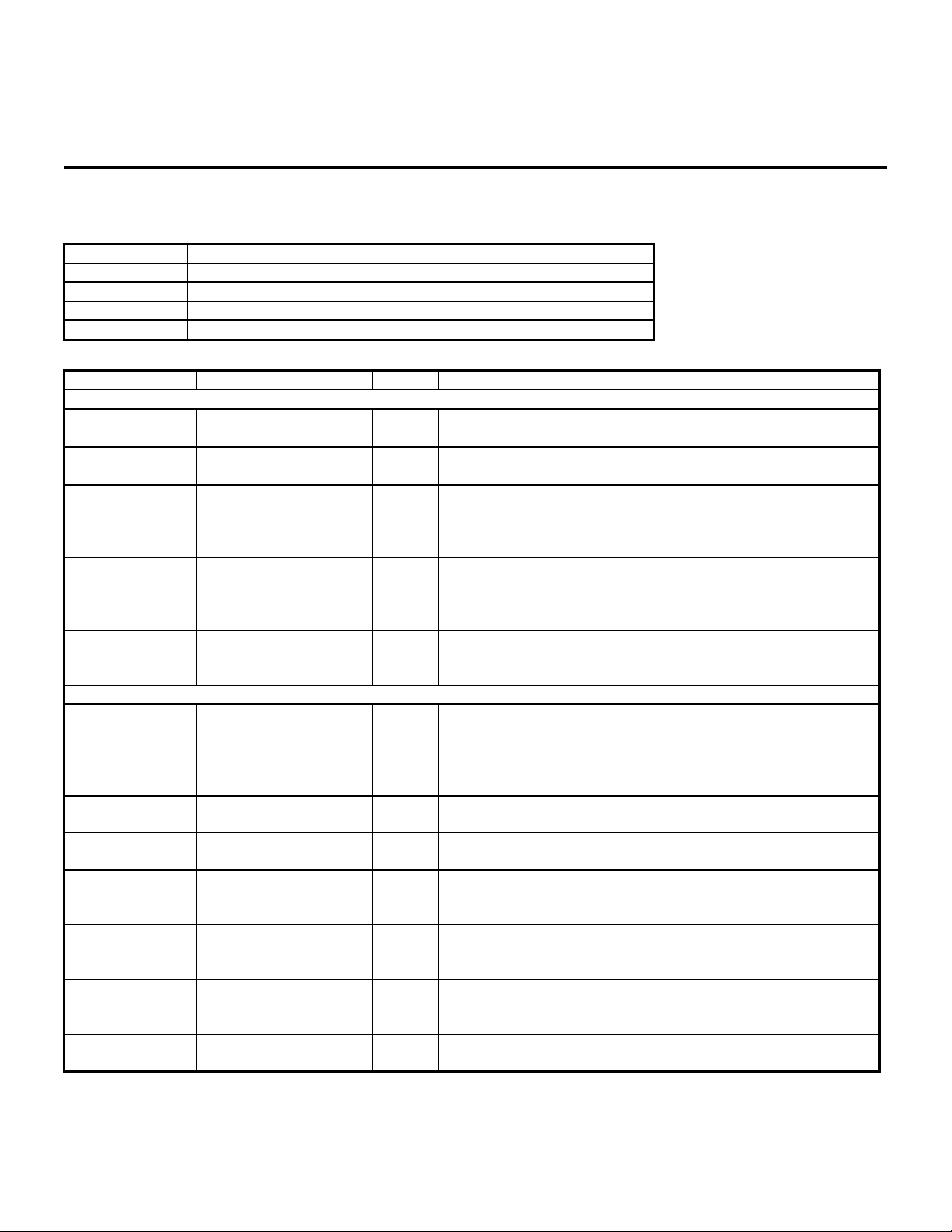
PIN Description
TYPE DESCRIPTION
I Used as Input pin
O Used as Output pin
I/O Used as Input and Output pin
O Used as Output with Open Drain
PIN NO. LABEL TYPE DESCRIPTION
Media Connections
104,105 RXIP,RXIM I
111,110 TXOP,TXOM O
1,2 FXRDP,FXRDM I
8,7 FXTDP,FXTDM O
3 FXSD I
MII Interface
59
30
52
39
53
35
58,57,56,55
31,32,33,34
65
45
70
46
72
47
73,74,75,76
48,49,50,51
TXER0
TXER1
TXEN0
TXEN1
TXCLK0
TXCLK1
TXD[3:0]0
TXD[3:0]1
RXDV0
RXDV1
RXER0
RXER1
RXCLK0
RXCLK1
RXD[3:0]0
RXD[3:0]1
I/O
O3s
O
O
O
Receiver Pair
Differential data from external transformers RD± pair.
Transmit Pair
Differential data to external transformers TD± pair.
Fiber Receiver Data Pair
Used to receiver the data from the fiber transceiver module,
need external pull high resistor and pull low resistor, depend
on impedance match of the fiber transceiver module.
Fiber Transmit Data Pair
It used as output the data into the fiber transceiver module,
need external pull high resistor and pull low resistor, depend
on impedance match of the fiber transceiver module.
Fiber Signal Detect
Used as an input pin from the Fiber transceiver module to
indicate a valid signal quality had been detect.
Transmit Error
I
ctive high. When an error happened in the transmit data
stream.
Transmit Enable
I
Active high. Indicate 4B data valid on TXD[3:0]
Transmit Clock
Output is 25MHz continuous clock.
Transmit Data Input
I
4B transmit data.
Receive Data valid
Active high. Indicates that a received frame is in progress,
and data on RXD pin is valid
Receive Error
It Indicate that there's an error during a receive frame when
high
Receive Clock
25MHz output. The clock is recovered from the incoming data
on the cable inputs
Receive Data Output
4B data output and synchronously to RXCLK.
TP112
3
TP112-DS-P02
Jan 5, 2000
 Loading...