


DM-121/SRM-121
User Manual
Ver
3.0

1
Copyright Notice
This document and product are copyrighted, September 2001, by ICP Electronics Inc.
All rights are reserved. No part of this manual may be reproduced, copied, or
translated without prior notice to ICP Electronics Inc.
The information provided in this document is for reference only. We do not assume
any responsibility arising out of the application of the products. This manual is subject
to change without any notice.
DM-121, SRM-121 and ICP are trademark of ICP Electronics Inc.

2
Table of Contents
Chapter 1 Product Information
1.1 Product Information and Specifications… .…………………….P3
1.2 Product Dimensions …………………………………………...P7
Chapter 2 System Setup
2.1 Front Panel Operations………………………………………….P8
2.2 LCD Installation………………………………………………...P9
2.3 Panel Mounting………………………………………………..P11
2.4 Arm Mounting …………………………………………………P12
2.5 Wall Mounting…………………………………………………P13
2.6 Rack Mounting ………………………………………………...P14
Chapter 3 User Mode OSD Information
3.1 User Mode Structure………………...………………………..P15
3.2 User Mode OSD Item description…………………………….p16
Appendix Check list………………………………………………P19

3
Chapter 1 Product Information
1.1 Product Specifications and Information
ICP Electronics Inc. is an expert in Industrial Computer solutions, manufacturer
and system integrator. We specialize in single board computers, chassis, workstations,
panel PC, flash disk, PC/104 products, power supply, and backplane. ICP operates a
worldwide network of distributors and sales representatives to offer customer the best
service.
IEI LCD monitor brings information everywhere. Even under the most severe
environments like steel plant or warehouse, DM/SRM series offer multiple mounting
options and brightness that meet your needs. The DM-121/ SRM-121 is a 12.1" flat
panel display specially designed to meet the applications for industrial environment.
l Suitable for panel mounting and 75/100mm interface pads for arm mounting
(conform to the proposed VESA standard)
l Panel Interface: Analog VGA signal ( by AV-9261 Analog VGA to Digital LCD
Interface Board)
l Front OSD control keys to adjust the best display quality.
l Side cabling design to less the LCD monitor’s total thickness
l Front plastic panel or aluminum material (DM-121-AL/ SRM-121-AL)
l Ship with power adapter for 100-240 VAC input
l Display Model (DM-121):
IMES 12.1” TFT M121- 53DH high brightness TFT LCD
Resolution: 800X600
MAX. Colors: 18 bits
Brightness: 250 cd/m
2
Hor. Frequency: 15-80KHz
Ver. Frequency: 50-85Hz
Operating Temperature: 0~50 oC
Storage Temperature: -20~60 oC
Viewing Angle(degree): R/L:180 U/D:30
LCD MTBF: 50,000 hrs
Backlight MTBF: 30,000 hrs

4
l Display Model (SRM-121):
LiteMAX 12.1” TFT SP1201 high brightness TFT LCD
Resolution: 800X600
MAX. Colors: 18 bits
Brightness: 1308 cd/m
2
Hor. Frequency: 15-80KHz
Ver. Frequency: 50-85Hz
Operating Temperature: 0~40oC
Storage Temperature: -20~60 oC
Viewing Angle (degree): R/L:180 U/D:30
LCD MTBF: 50,000 hrs
Backlight MTBF: 20,000 hrs
l Option Touch Screen : Dynapro 12.1”
Type: Analog Resistive
Resolution: Continuous
Light transmission: Typical value 75%
Surface Hardness: 4H (Test condition: ASTM D3363-92A)
8-wire touch screen
Touch screen interface: RS-232
Support driver: Linux,MS-DOS,Windows 3.1/95/
98/CE,ME/2000/NT,OS/2,MAC,etc.
l Environmental specifications
Operating Temperature : 0 ~ 50℃
Relative Humidity: 10-95% @0~50 ℃, non-condensing
Vibration: 5 to 17 Hz 0.1" double-amplitude displacements,
17 to 640 Hz 1.5 G Peak to peak

5
l Power supply: (DM-121)
Model no: UP06031120A
Input requirements:
Input Voltage range: 90 to 264 VAC.
Line frequency: 47 to 63 HZ.
In-Rush current: 80 A max.
Input current: 1.4 A max.
Output:
Output Voltage range: +11.4V ~+12.6V (tolerance: ±5%) 3.8A 45 Watt
Ripple and Noise at +12V Voltage
Maximum peak to peak ripple and noise: 120mV
Operating environmental conditions:
Ambient Temperature: 0°C~50°C.
Relative Humidity: 10%~95%.
Altitude: Sea level to 12,000 feet.
Vibration: 1.0mm, 10-25Hz, 15 minutes per cycle for each Axis (X, Y, Z).
EMI emissions:
The power supply meets the radiated and conducted emission requirements for
a (CISPR22 CLASS B) and a (FCC CLASS B).
MTBF:
When the power supply is operated within any of the limits of this power
supply’s specification, the MTBF shall be at least 50,000 hours at 25°C.
** System Power Consumption: 12V / 1.3A(not include touch screen)

6
l Power supply: (SRM-121)
Model no: PSA65U-120
Input requirements:
Input Voltage range: 90 to 264 VAC.
Line frequency: 47 to 63 HZ.
In-Rush current: 30A max@115VAC ,60A max@230VAC at 25℃.
Input current: 1.5 A max@115VAC, 0.8A max@230VAC.
Output:
Output Voltage range: +12V ±0.5V 5A 60 Watt
Ripple and Noise at Voltage 120 mvP
Operating environmental conditions:
Ambient Temperature: 0°C~40°C.
Relative Humidity: 5%~95%.
Altitude: Sea level to 10,000 feet.
Vibration: 10-55Hz, 15 minutes X, Y, Z Axis cycle: 20.
EMI emissions:
The power supply meets the radiated and conducted emission requirements for
a (CISPR22 CLASS B) and a (FCC CLASS B).
MTBF:
When the power supply is operated within any of the limits of this power
supply’s specification, the MTBF shall be at least 50,000 hours at 25°C.
** System Power Consumption: 12V / 2.4A(not include touch screen)

7
1.2 Product Dimensions
The following diagrams indicate the dimensions of DM-121/SRM-121.
Front Panel: 340mm x 260mm x 9mm (WxHxD)
Cabinet: 310mm x 230mm x 43.7mm (WxHxD)……DM-121
Cabinet: 310mm x 230mm x 56.6mm (WxHxD)……SRM-121
(Unit: mm)
SRM-121
DM-121
210
43.7
6.1
18.1
102
310
210
56.6
310
102
6.1
28.4
340
186
247
260
230
9
"*" Front panel of thickness.
the thickness is 8 mm.By DM-121-AL / SRM-121-AL
*

8
Chapter 2 System Setup
The DM-121/ SRM-121 is very easy to be set up for operation. As you set up your
system, please refer to the following procedures.
2.1 Front panel operation
LCD on/off Button
Exit Button
Up Button
Down Button
Menu Button
POWER LED Indicate

9
2.2 LCD Installation
DM-121/SRM-121 provides two features for your choosing: one is LCD only; the
other is LCD with touch screen. You can use VGA cable connects from LCD panel
to your system VGA interface.
2.2.1 LCD without Touch Screen
There are five LCD adjustment switches on the rear panel of DM-121/SRM-121.
Also, there are two ports for VGA and RS-232. If you want to install LCD
without Touch Screen, just connect the VGA Card to the VGA Signal Input port.
The power connection you can cho ose 12V DC jack or terminal block use to 12V
DC input.
(OPTION)
RS-232
INPUT
VGA SIGNAL
ExitUPDNMENU
(under diagram)
VIEW THE SIDE
VGA
INPUT
POWER INPUT
12VGnd
RS-232
(OPTION)
12V DC
DC
GndBOTTON
OSD
CAUTION: FOR INDOOR USE ONLY
POWER INPUT:
Black color: to Gnd
Yellow color: to +12VDC

10
2.2.2 LCD with Touch Screen
If you want to install LCD with Touch Screen, please connect RS232 connector from
LCD to your COM port from CPU card. The driver for touch screen we used the CD
disk with system shipping.

11
2.3 Panel Mounting
DM-121/SRM-121 is either suitable for panel mounting. As you mount this flat
panel display, please refer to the diagram below.
312.0
232.0
UNIT:mm
THE DIMENSION IS FOR PANEL MOUNTING
(The flat panel thickness is 6mm or less than 6mm)
STEP 1
STEP 2
STEP 2
STEP 2
STEP 2
Less than 6.0mm

12
2.4 Arm Mounting
DM-121/SRM-121 is suitable for 75/100mm interface pads or for arm mounting.
arm mounting and the specification conform to the proposed VESA standard.
75.0
100.0
100.0
75.0
13
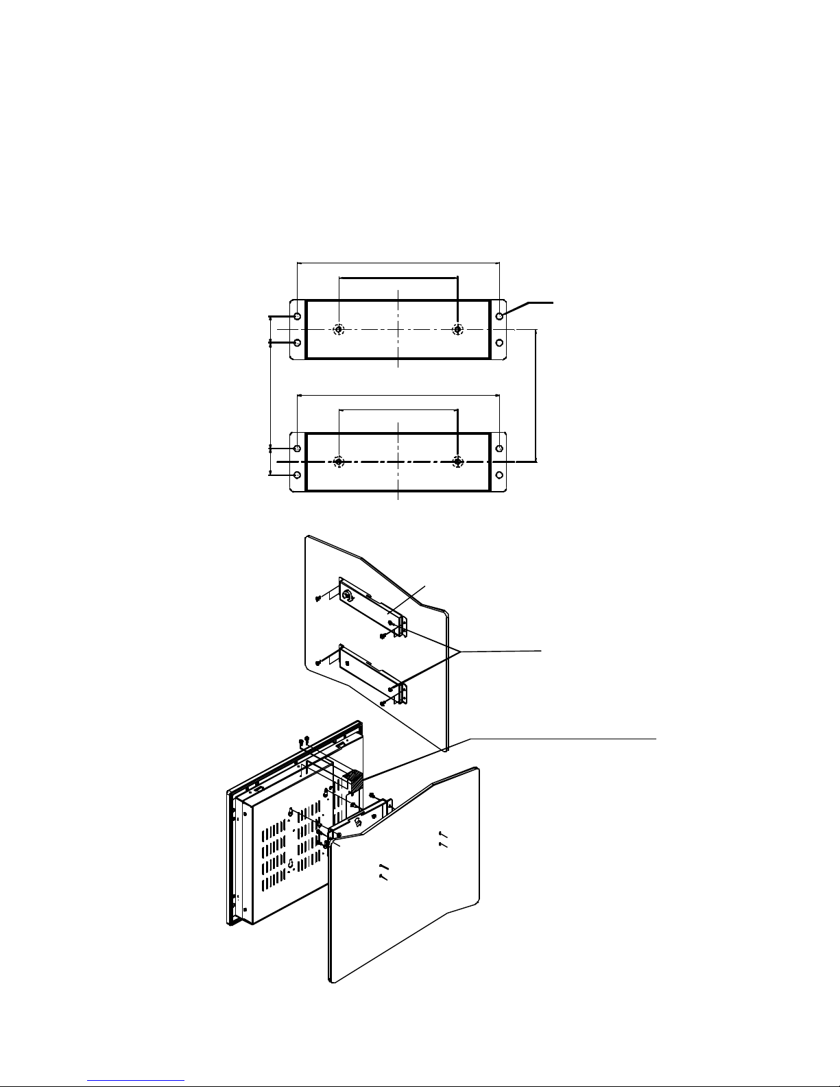
2.5 Wall Mounting
DM-121/SRM-121 is suitable for wall mounting and the specification conform to the
proposed.
153.00
90.00
153.00
90.00
80.00
20.0
20.0
8-D4.5
100.00
Wall
WALL-MOUNT BRACKET
WALL-MOUNT VIBRATION KIT
SCREW BOLT
STEP 1
STEP 2
STEP 4
STEP 3
Wall

14
2.6 Rack Mounting
DM/SRM-121 provide option rackmount kit for industrial Rack. The following
diagram shows how to mount DM/SRM-121 onto the 19" Rack.
321.40±0.25
200.00±0.15
483.00
463.00±0.2
312.00
448.00
234.85±0.2
R3.25
2.00
57.15±0.1
4-R5.00
8-O3.80
184.00
241.40
232.00
310.00
1.60
R3.00
17.00
Rackmount Kit Dimension
Rackmount-Kit
STEP 1
STEP 2
STEP 4
STEP 3

15
Chapter 3 User Mode OSD Information
3.1 User Mode OSD Structure
LEVEL 0 LEVEL 1 VALUE
RGB Menu Brightness Press Select Button
Red -127 ~ 127
Green -127 ~ 127
Blue -127 ~ 127
Color Temp 0 ~ 7
Sharpness 0 , 1
Main Menu Press Select Button
Geometry Menu Auto-Adjustment Press Select Button
H. Position 0 ~ 252
V. Position 1 ~ 26
H. Total 1004 ~ 1108
Auto Phase Press Select Button
Delay 0 ~ 61
Main Menu Press Select Button
Contrast Menu Auto-Balance Press Select Button
Contrast Press Select Button
Red 0 ~ 511
Green 0 ~ 511
Blue 0 ~ 511
Balance Press Select Button
Red 0 ~ 127
Green 0 ~ 127
Blue 0 ~ 127
Main Menu Press Select Button
Language Menu English Press Select Button
Spanish Press Select Button
Main Menu
Auto Training ON/OFF
DOS/GFX ON/OFF
NVRAM init Press Select Button
Power Down Press Select Button
Revert Press Select Button
Save Press Select Button

16
3.2 User Mode OSD Item description
l Auto-Adjustment
This item will automatically adjust the H/V position, frequency, phase, and black
level.
l Auto Phase
This item will automatically adjust the sampling.
l Brightness
It is used to adjust the brightness of screen. This function will adjust the offset
value of ADC. Please take note that setting this value too high or too low will
destroy the quality of image.
l Contrast
It is used to adjust the contrast of screen, this function will adjust the gain value
of ADC. Please take note that adjusting this value too high or too low will
destroy the quality of image.

17
l DOS/GFX
It is used to choose VGA Input signal that is text mode or graphic mode. (It is only
selectable on resolution of 720/640x400 or 720/640x350.) 400 and 350 standard
IBM mode have the same Hsync. and Vsync. Value. AV-9261 MPU can not
differentiate them automatically and users need to adjust them by manual to match
proper VGA mode.
l H. Position
It is used to adjust horizontal display position of image.
l V. Position
It is used to adjust vertical display position of image.
l Language
It is used to select the languages using on OSD display. AV-9261 now can
support 2 languages on OSD display. English is the default language .

18
l Revert
It is used to reload original parameters from the factory’s OSD data area of the
system EEPROM 24c16 device to re-initialize AV-9261 system device. When
users adjust OSD data too much and can not see better quality than before, users
can select this item, Revert, and MPU will reload default BIOS setting and reinitialize the system.
l Save
It is used to save the parameters into the user OSD adjustment data area of the
system EEPROM 24c16 device and close OSD. Whenever users adjust any
parameters, it is necessary to execute this item to save data into EEPROM. And
next time power on, the MPU will use the storied data to initialize the AV-9261
system.
l Main Menu
Every level of OSD has the item name, Main Menu that lets users leave current
level and jump to upper level, or press the Return key.
l Exit
Press the EXIT key to exit the OSD menu when the OSD menu is on the top of
the level.

19
Appendix Check List
Item Part No. Description Qty.
1
14106031120A-00-020
63PSA65U120-000
POWER SUPPLY..POTRANS POWER(DM-121)
POWER SUPPLY..POTRANS POWER(SRM-121)
1
2
32000-000002 POWER CORD/175CM
1
3
32000-000042 VGA CABLE D-SUB 15P M TO M/180CM
1
4
32100-041000 WIRE CABLE/40CM
1
5
42011-000150 PANEL-MOUNT KIT
4
6
41014-011602 WALL-MOUNT VIBRATION KIT
1
7
41020-002702 WALL-MOUNT BRACKET
2
8
42005-000603 SCREW BOLT
4
9
44003-050501 SCREW M5X50
4
10
44033-030061 SCREW M3
10
11
44033-040062 SREW M4
8
12
32000-000098 ROUND CABLE D-SUB 9P /180CM,
For: TOUCH SCREEN (OPTIONAL)
1
 Loading...