

ICP DAS ZT-2018S User Manual

ICP DAS, ZT-2018/S AI Series User Manual, Version 1.0.1 Page 1
Copyright © 2013 by ICP DAS Co., Ltd. All Rights Reserved.
ZT-2018/S
User Manual
Warranty
All products manufactured by ICP DAS are under warranty regarding
defective materials for a period of one year, beginning from the date of
delivery to the original purchaser.
Warning
ICP DAS assumes no liability for any damage resulting from the use of this
product. ICP DAS reserves the right to change this manual at any time
without notice. The information furnished by ICP DAS is believed to be
accurate and reliable. However, no responsibility is assumed by ICP DAS for
its use, nor for any infringements of patents or other rights of third parties
resulting from its use.
Copyright
Copyright © 2013 by ICP DAS. All rights are reserved.
Trademarks
Names are used for identification purposes only and may be registered
trademarks of their respective companies.
Technical Support
If you have any problems, please feel free to contact us via email at
service@icpdas.com.

ICP DAS, ZT-2018/S AI Series User Manual, Version 1.0.1 Page 2
Copyright © 2013 by ICP DAS Co., Ltd. All Rights Reserved.
Table of Contents
1 Introduction ................................................. 6
1.1 Introduction to ZigBee ................................... 6
1.2 Introduction to the ZT-2000 I/O Series ................... 7
2 Hardware Information .......................................... 8
2.1 Specifications ........................................... 8
2.2 Pin Assignments ......................................... 10
2.3 Wire Connections ........................................ 10
3 Setting up the ZT-2000 I/O Device ............................ 11
3.1 Introduction to the Configuration Parameters ............ 11
3.2 Introduction to the Rotary and DIP Switches ............. 12
3.3 Starting the ZT-2000 I/O Device ......................... 15
3.4 Communications Testing .................................. 15
3.5 Examples ................................................ 16
4 Analog Input Type and Data Format ............................ 18
5 Calibration .................................................. 21
6 The DCON/Modbus RTU Command Sets ............................. 22
6.1 Communicating with the ZT-2000 I/O Device ............... 22
6.2 The DCON Protocol Command Set ........................... 22
6.2.1 Checksum ......................................... 23
6.3 Overview of the DCON Command Set ........................ 24
6.3.1 #AA .............................................. 28
6.3.2 #AAN ............................................. 29
6.3.3 $AA0 ............................................. 31
6.3.4 $AA1 ............................................. 33
6.3.5 $AA2 ............................................. 35
6.3.6 $AA3 ............................................. 36
6.3.7 $AA5 ............................................. 37
6.3.8 $AA5VV ........................................... 38
6.3.9 $AA6 ............................................. 39
6.3.10 $AA7CiRrr ........................................ 40

ICP DAS, ZT-2018/S AI Series User Manual, Version 1.0.1 Page 3
Copyright © 2013 by ICP DAS Co., Ltd. All Rights Reserved.
6.3.11 $AA8Ci ........................................... 42
6.3.12 $AA9 ............................................. 44
6.3.13 $AA9SNNNN ........................................ 45
6.3.14 $AA9Ci ........................................... 47
6.3.15 $AA9SNNNNCi ...................................... 49
6.3.16 $AAA ............................................. 51
6.3.17 $AAAi ............................................ 52
6.3.18 $AAF ............................................. 54
6.3.19 $AAM ............................................. 55
6.3.20 $AAS1 ............................................ 56
6.3.21 ~** .............................................. 57
6.3.22 ~AA0 ............................................. 58
6.3.23 ~AA1 ............................................. 60
6.3.24 ~AA2 ............................................. 61
6.3.25 ~AA3ETT .......................................... 63
6.3.26 ~AAC ............................................. 65
6.3.27 ~AACN ............................................ 66
6.3.28 ~AAEV ............................................ 67
6.3.29 ~AAO(Name) ....................................... 69
6.3.30 @AACH ............................................ 70
6.3.31 @AACHi ........................................... 71
6.3.32 @AACHCi .......................................... 73
6.3.33 @AACL ............................................ 75
6.3.34 @AACLi ........................................... 77
6.3.35 @AACLCi .......................................... 79
6.3.36 @AADHCi .......................................... 81
6.3.37 @AADI ............................................ 83
6.3.38 @AADLCi .......................................... 84
6.3.39 @AAHI(Data)CiT ................................... 86
6.3.40 @AALO(Data)CiT ................................... 88
6.3.41 @AAOD ............................................ 90
6.3.42 @AARH ............................................ 91
6.3.43 @AARHi ........................................... 92
6.3.44 @AARHCi .......................................... 93
6.3.45 @AARL ............................................ 95
6.3.46 @AARLi ........................................... 96
6.3.47 @AARLCi .......................................... 97
6.4 Modbus RTU Protocol Command set ......................... 99
6.4.1 Modbus Address Mapping .......................... 100

ICP DAS, ZT-2018/S AI Series User Manual, Version 1.0.1 Page 4
Copyright © 2013 by ICP DAS Co., Ltd. All Rights Reserved.
6.4.2 PLC Address Mapping ............................. 103
6.4.3 01 (0x01) Reading the Coils ..................... 104
6.4.4 02 (0x02) Reading the Discrete Inputs........... 105
6.4.5 03 (0x03) Reading Multiple Registers............ 106
6.4.6 04 (0x04) Reading Multiple Input Registers ..... 107
6.4.7 05 (0x05) Writing a Single Coil ................. 108
6.4.8 06 (0x06) Writing Multiple Registers............ 109
6.4.9 15 (0x0F) Writing Multiple Coils ................ 110
6.4.10 70 (0x46) Reading/Writing the Module Settings .. 111
7 Appendix .................................................... 125
7.1 Software Configuration Mode ............................ 125
7.2 Dual Watchdog Operation ................................ 126
7.3 Reset Status ........................................... 127
8 Troubleshooting ............................................. 128

ICP DAS, ZT-2018/S AI Series User Manual, Version 1.0.1 Page 5
Copyright © 2013 by ICP DAS Co., Ltd. All Rights Reserved.
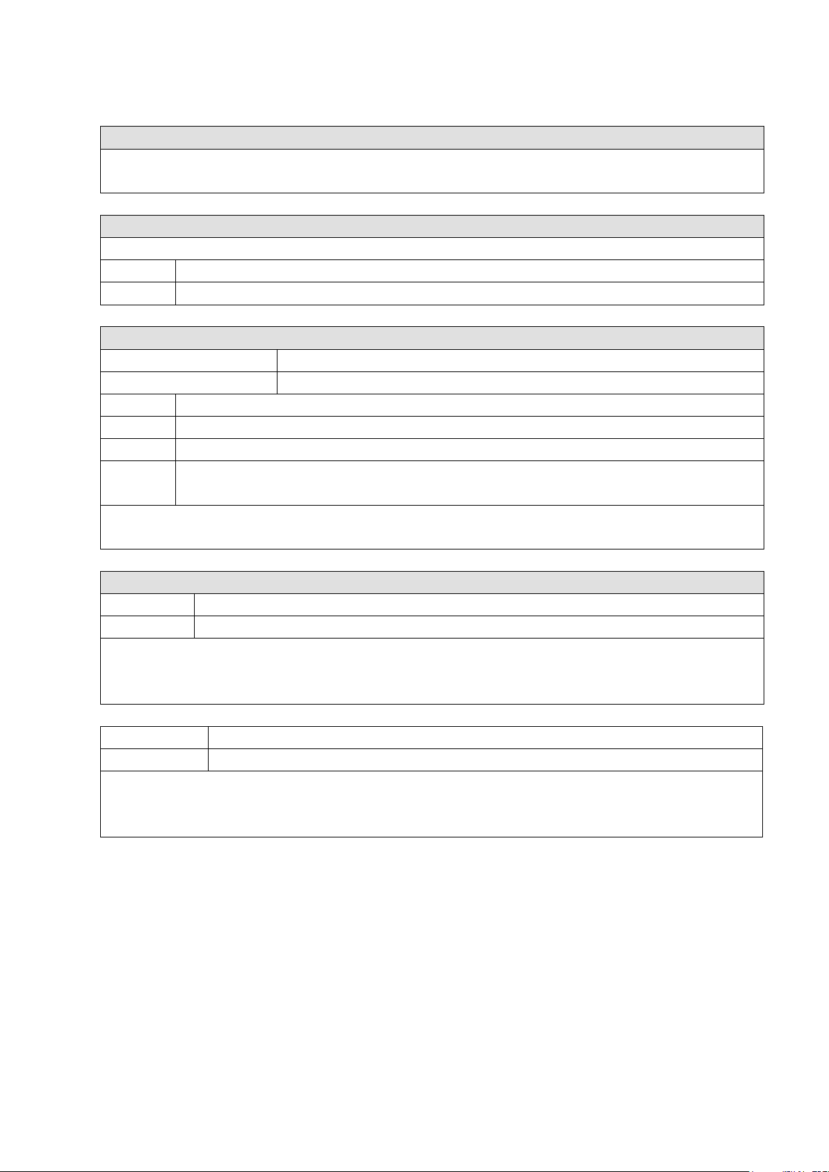
What’s in the Shipping Package?
The shipping package contains the following items:
More Information
Documentation:
All documentation related to the ZT Series of devices can be found on the
companion CD at:
CD: \Napdos\ZigBee\ZT_Series\Document
Or can be downloaded from:
HTUhttp://ftp.icpdas.com/pub/cd/usbcd/napdos/zigbee/zt_series/documentUT
Software:
Utility software for the ZT Series of devices can be found on the companion CD at:
CD: \Napdos\ZigBee\ZT_Series\Utility
Or can be downloaded from:
HTUhttp://ftp.icpdas.com/pub/cd/usbcd/napdos/zigbee/zt_series/utilityUT
ANT-124-05
ZT-2018
Quick Start
DN-1824
CD
If any of these items are missing or damaged, please contact your local distributor for more
information. Save the shipping materials and cartons in case you need to ship the module in the
future.

ICP DAS, ZT-2018/S AI Series User Manual, Version 1.0.1 Page 6
Copyright © 2013 by ICP DAS Co., Ltd. All Rights Reserved.
1 Introduction
1.1 Introduction to ZigBee
ZigBee is a specification for a suite of high-level communication protocols using
small, low-power digital radios based on the IEEE 802.15.4 standard for personal area
networks. ZigBee devices are often used in mesh network form to transmit data over
longer distances, passing data through intermediate devices to reach more distant ones.
This allows ZigBee networks to be formed ad-hoc, with no centralized control or
high-power transmitter/receiver required in order to reach all of the devices. Any
ZigBee device can be tasked with running the network.
ZigBee is targeted at applications that require a low data rate, long battery life, and
secure networking. ZigBee has a defined transmission rate of 250 kbit/s, best suited for
periodic or intermittent transmission of data, or for a single signal transmission from a
sensor or input device. Applications include wireless light switches, electrical meters
with in-home-displays, traffic management systems, and other consumer and industrial
equipment that requires short-range wireless transfer of data at relatively low rates.
The technology defined by the ZigBee specification is intended to be simpler and less
expensive than other WPANs.

ICP DAS, ZT-2018/S AI Series User Manual, Version 1.0.1 Page 7
Copyright © 2013 by ICP DAS Co., Ltd. All Rights Reserved.
1.2 Introduction to the ZT-2000 I/O Series
The ZT-2000 I/O series of devices are small wireless ZigBee I/O modules based
on the IEEE802.15.4 standard that allow data acquisition and control via personal area
ZigBee networks. See Section 3.1 for more detailed information.
The ZT-2000 I/O series is a wireless data acquisition-based client/server system.
Accordingly, a Net Server for the ZigBee (ZT-2570/ZT-2550) is essential in such
systems. For more information regarding any configuration issues related to the ZigBee
Coordinator, please refer to the “ZT-25XX ZigBee Converter Quick Start” document,
which can be found at:
http://ftp.icpdas.com/pub/cd/usbcd/napdos/zigbee/zt_series/document/

ICP DAS, ZT-2018/S AI Series User Manual, Version 1.0.1 Page 8
Copyright © 2013 by ICP DAS Co., Ltd. All Rights Reserved.
2 Hardware Information
2.1 Specifications
ZT-2018/S
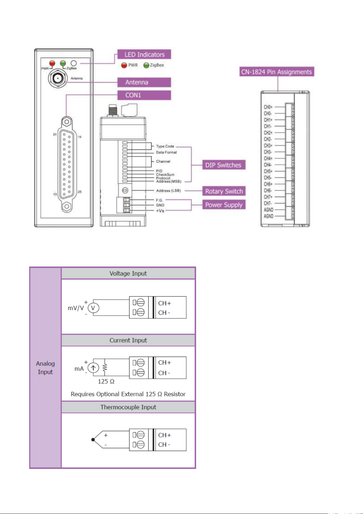
Analog Input
Input Channels
8 Differential
Input Type
+/-15 mV, +/-50 mV, +/-100 mV, +/-500 mV, +/-1V,
+/-2.5V, +/-20 mA, 0 ~ 20 mA, 4 ~ 20 mA (Current Input
Requires Optional External 125 Ω Resistor). Thermocouple
(J, K, T, E. R. S, B, N, C, L, M, LDIN43710)
Resolution
16-bit
Sampling Rate
16-bit, 10 Samples/Sec. (Total)
Accuracy
+/-0.1% FSR
-3dB Bandwidth
15.7 Hz
Zero Drift
+/-10 μV/°C
Span Drift
+/-25 ppm/°C
Common Mode Rejection
86 dB
Normal Mode Rejection
100 dB
Input Impedance
>400 kΩ
Open Thermocouple Detection
Yes
Overvoltage Protection
240 Vrms
Intra-module Isolation,
Field-to-Logic
3000 VDC
ESD Protection
+/-4 kV Contact for each Channel
LED Indicators
ZigBee PWR
ZigBee Device Power
ZigBee Net
ZigBee Communication Indicator
Power
Power Consumption
0.88 W (Max.)
Environment
Operating Temperature
-25 to 75°C
Storage Temperature
-30 to 80°C
Humidity
10 to 90%, Non-condensing

ICP DAS, ZT-2018/S AI Series User Manual, Version 1.0.1 Page 9
Copyright © 2013 by ICP DAS Co., Ltd. All Rights Reserved.
Wireless
RF Channels
16
RF Transmit Power
11 dBm
Antenna (2.4 GHz)
5 dBi Omnidirectional
Transmission Range (LOS)
700 m (Typical)
Max. Slaves Supported
255
EMI Certification
CE/FCC, FCC ID
ICP DAS, ZT-2018/S AI Series User Manual, Version 1.0.1 Page 10
Copyright © 2013 by ICP DAS Co., Ltd. All Rights Reserved.
2.2 Pin Assignments
2.3 Wire Connections
ICP DAS, ZT-2018/S AI Series User Manual, Version 1.0.1 Page 11
Copyright © 2013 by ICP DAS Co., Ltd. All Rights Reserved.
3 Setting up the ZT-2000 I/O Device
3.1 Introduction to the Configuration
Parameters
A. The “ZB PID” parameter is the group identity for a ZigBee network, and must
be the same for all devices in the same ZigBee network.
B. The “Node ID” parameter is the individual identity of the specific ZigBee
module, and must be unique for each device connected to the same ZigBee
network.
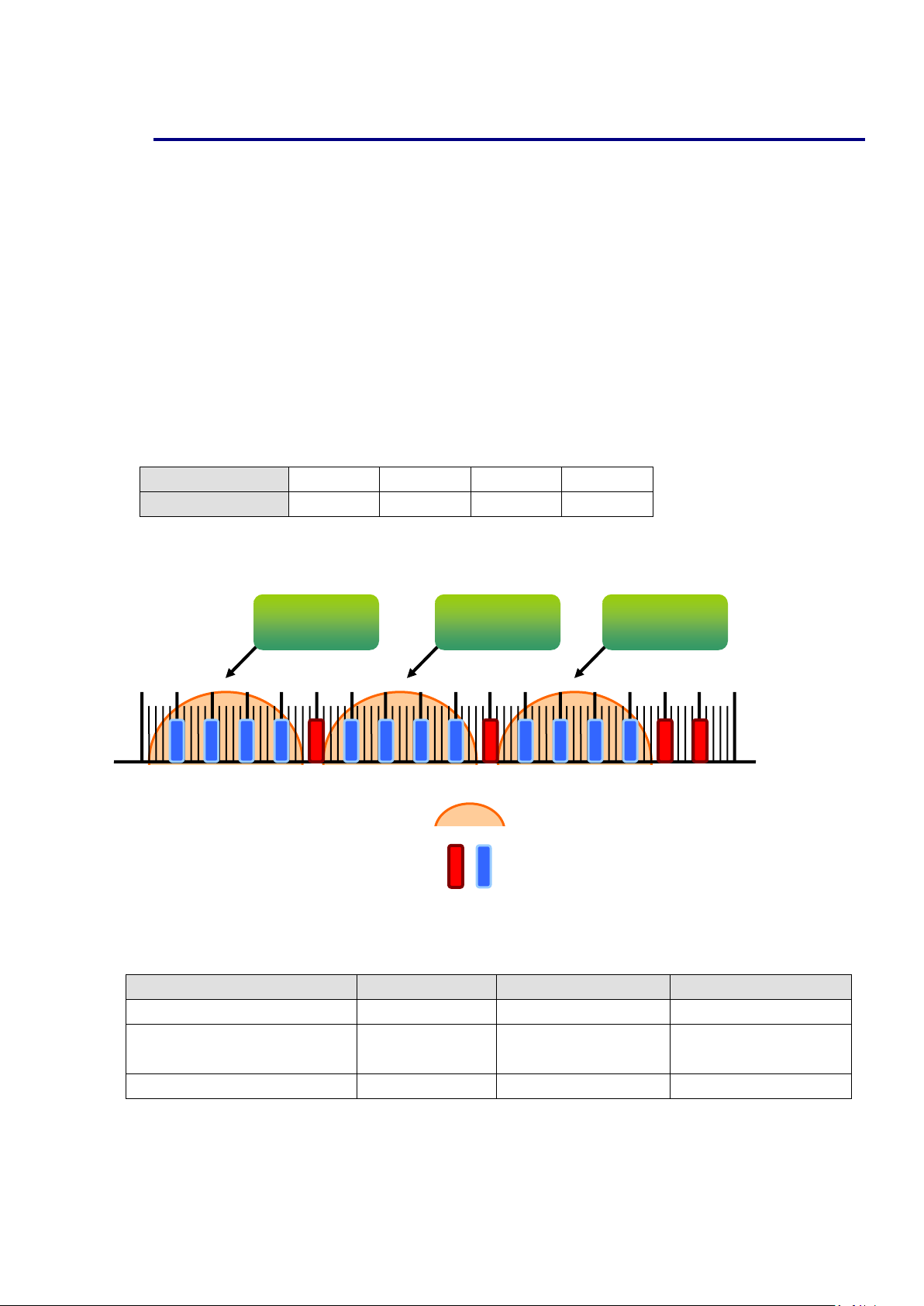
C. The “ZB Channel” parameter indicates the radio frequency channel, and must
be set to the same value as other modules on the same ZigBee network.
ZB Channel
0x00
0x01
……
0x0F
Frequency (MHz)
2405
2410
……
2480
※ ZB channels 0x04, 0x09, 0x0E or 0x0F are recommended because they do not overlap with
the Wi-Fi frequency band.
D. Protocol/Application Mode:
When implementing custom programs based on different protocols, the following
application mode(s) are recommended in order to ensure optimal performance.
User Program Protocol
ZT-2000
ZT-2550
ZT-2570
DCON
DCON
Transparent
Transparent
Modbus RTU
Modbus RTU
Transparent
Modbus Gateway
Transparent
Modbus Gateway
Modbus TCP
Modbus RTU
------
Modbus Gateway
00 01 02 03 04 05 06 07 08 09 0A 0B 0C 0D 0E 0F
802.11b/g
ZB Channel 1
802.11b/g
ZB Channel 6
802.11b/g
ZB Channel 11
802.11b/g ZB Channel (North America)
802.15.4 ZB Channel
2400
MHz
2485
MHz
ICP DAS, ZT-2018/S AI Series User Manual, Version 1.0.1 Page 12
Copyright © 2013 by ICP DAS Co., Ltd. All Rights Reserved.
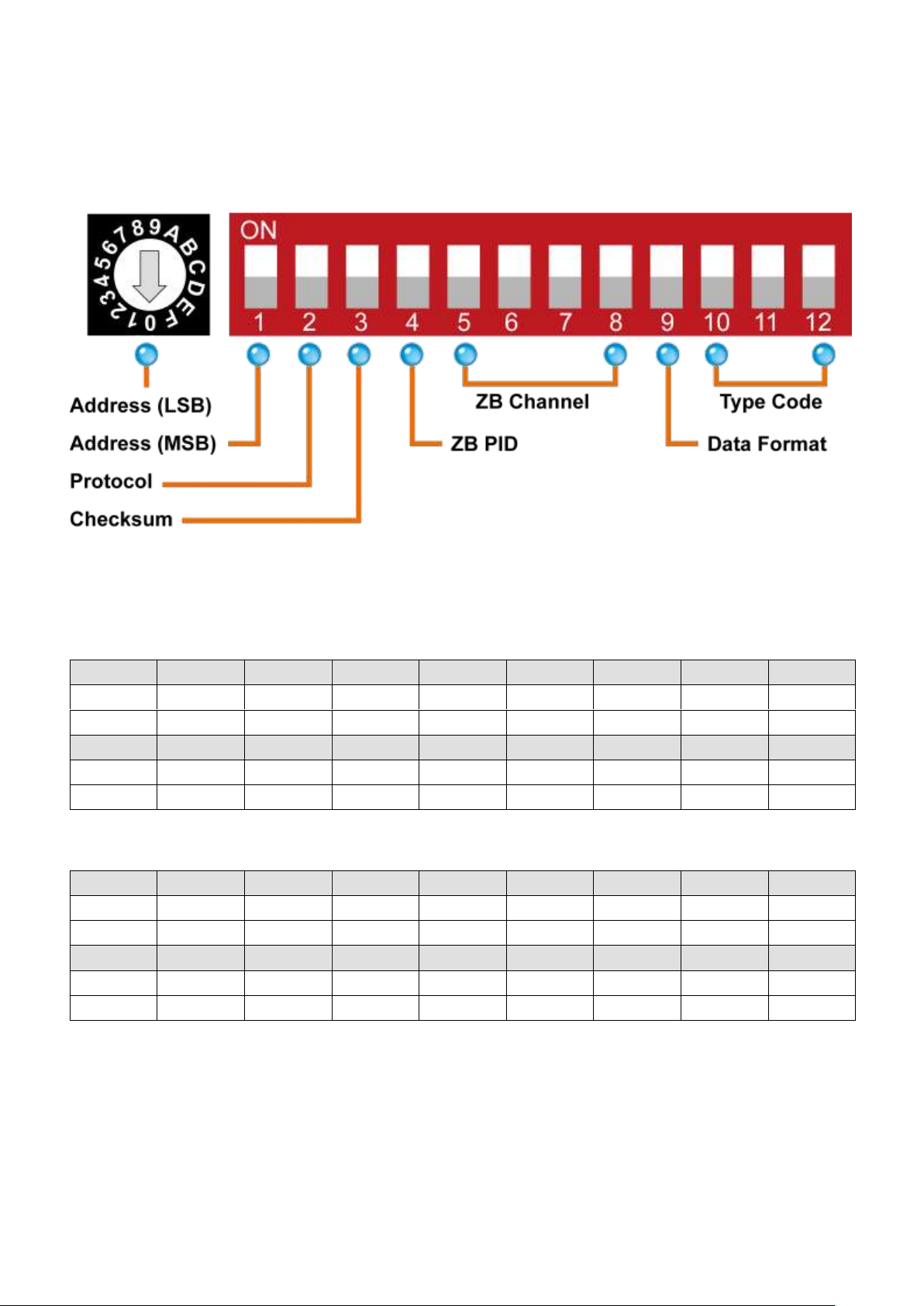
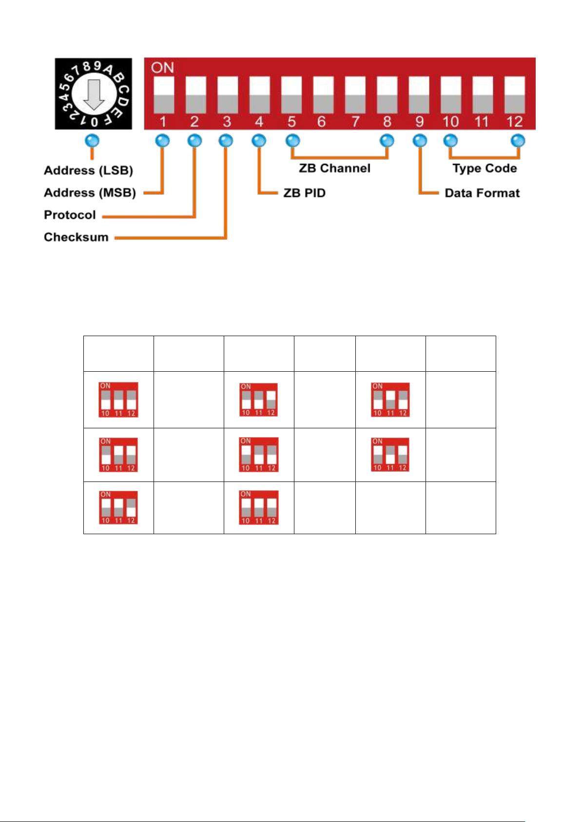
3.2 Introduction to the Rotary and DIP Switches
The configuration of the ZT-2018/S can be adjusted using a combination of the
external rotary switch and the DIP switches. The ZT-2000 device should only be
rebooted once the configuration is complete.
Rotary Switch
Case 1: Address MSB = 0
0 1 2 3 4 5 6 7
Address
*Note 1
01
02
03
04
05
06
07
Node ID
*Note 1
0x0001
0x0002
0x003
0x0004
0x0005
0x0006
0x0007
8 9 A B C D E F
Address
08
09
0A
0B
0C
0D
0E
0F
Node ID
0x008
0x0009
0x000A
0x000B
0x000C
0x000D
0x000E
0x000F
Case 2: Address MSB = 1
0 1 2 3 4 5 6 7
Address
10
11
12
13
14
15
16
17
Node ID
0x0010
0x0011
0x0012
0x013
0x0014
0x0015
0x0016
0x0017
8 9 A B C D E F
Address
18
19
1A
0B
0C
1D
1E
1F
Node ID
0x018
0x0019
0x001A
0x001B
0x001C
0x001D
0x001E
0x001F
*Note 1: The “Address” and “Node ID” values are defined via the $AANNTTCCFF command.
In software configuration mode, the DIP switches for “Address”, “Data Format”
and “Type Code” are ignored and can also be set via the %AANNTTCCFF and $AACiRrr
commands.
ICP DAS, ZT-2018/S AI Series User Manual, Version 1.0.1 Page 13
Copyright © 2013 by ICP DAS Co., Ltd. All Rights Reserved.
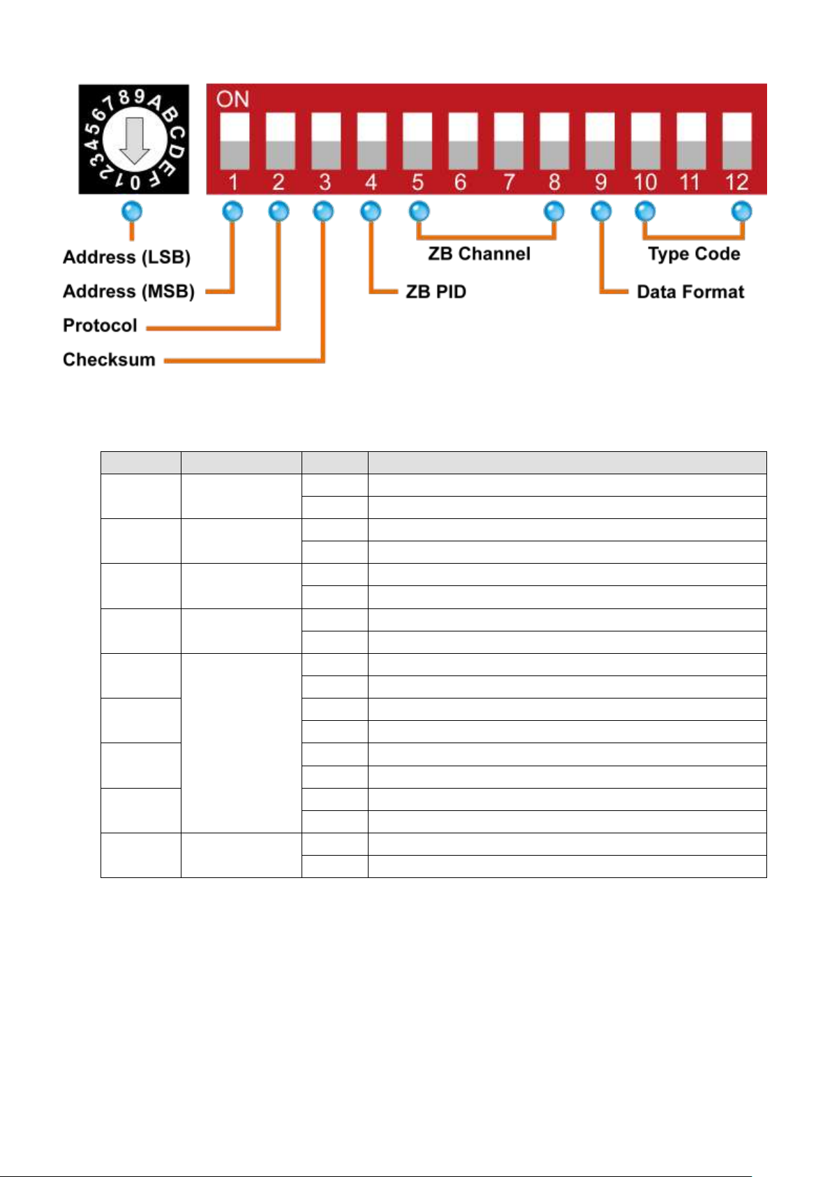
DIP Switches
Number
Item
Status
Description
1
Address MSB
OFF
Valid Address (Node ID) from 0x01 to 0x0F
ON
Valid Address (Node ID) from 0x10, 0x01 to 0x1F
2
Protocol
OFF
DCON Protocol
ON
Modbus RTU Protocol
3
Checksum
OFF
Disabled (DCON Protocol)
ON
Enabled (DCON Protocol)
4
ZB PID
OFF
ZigBee Pan ID = 0x0000
ON
ZigBee Pan ID = 0x0001
5
ZB Channel
OFF
------
ON
0x08 6 OFF
------
ON
0x04 7 OFF
------
ON
0x02
8
OFF
------
ON
0x01
9
Data Format
OFF
Engineering Units Format
ON
Hexadecimal Format
ICP DAS, ZT-2018/S AI Series User Manual, Version 1.0.1 Page 14
Copyright © 2013 by ICP DAS Co., Ltd. All Rights Reserved.
Type Code
DIP switches 10-12 are used to define the input Type Code for the ZT-2018/S, as
shown below.
Switch
Position
Type Code
Switch
Position
Type
Code
Switch
Position
Type Code
0x00
0x01
0x02
0x03
0x04
0x05
0x06
0x07

ICP DAS, ZT-2018/S AI Series User Manual, Version 1.0.1 Page 15
Copyright © 2013 by ICP DAS Co., Ltd. All Rights Reserved.
3.3 Starting the ZT-2000 I/O Device
As the ZigBee network is controlled by the ZigBee Coordinator, the ZT-2550/ZT-2570
(ZigBee Coordinator) must be configured first. Refer to the documents section below
for full details of how to configure these devices.
Once configuration of the ZigBee Coordinator has been completed, set the “ZB PID”
and “ZB Channel” values for the ZT-2000 I/O device to the same values as the
network, and then reboot the device. The module will automatically start to function on
the ZigBee network using the default protocol.
※ Documents
Helpful documentation related to the ZT-2550 and ZT-2570 can be found at:
http://ftp.icpdas.com.tw/pub/cd/usbcd/napdos/zigbee/zt_series/document/zt-255x/
http://ftp.icpdas.com.tw/pub/cd/usbcd/napdos/zigbee/zt_series/document/zt-257x/
※ Configuration Utility
A utility that can be used to configure the ZT-2000 I/O device Coordinator is available
for download from:
http://ftp.icpdas.com.tw/pub/cd/usbcd/napdos/zigbee/zt_series/utility/
3.4 Communications Testing
Once the ZT-2000 I/O device has joined the ZigBee network, the signal quality can be
confirmed by monitoring the status of the ZigBee Net LED indicators. If the LED
indicator shows a steady light, communication with the ZT-2000 I/O device has been
successfully established for data acquisition and control.
ICP DAS provides the “DCON Utility” which can be used to simulate DCON/Modbus
communication. This software can also be used to verify the device settings and the
ZigBee I/O functions.
The DCON Utility can be downloaded from:
http://ftp.icpdas.com/pub/cd/8000cd/napdos/driver/dcon_utility/
ICP DAS, ZT-2018/S AI Series User Manual, Version 1.0.1 Page 16
Copyright © 2013 by ICP DAS Co., Ltd. All Rights Reserved.
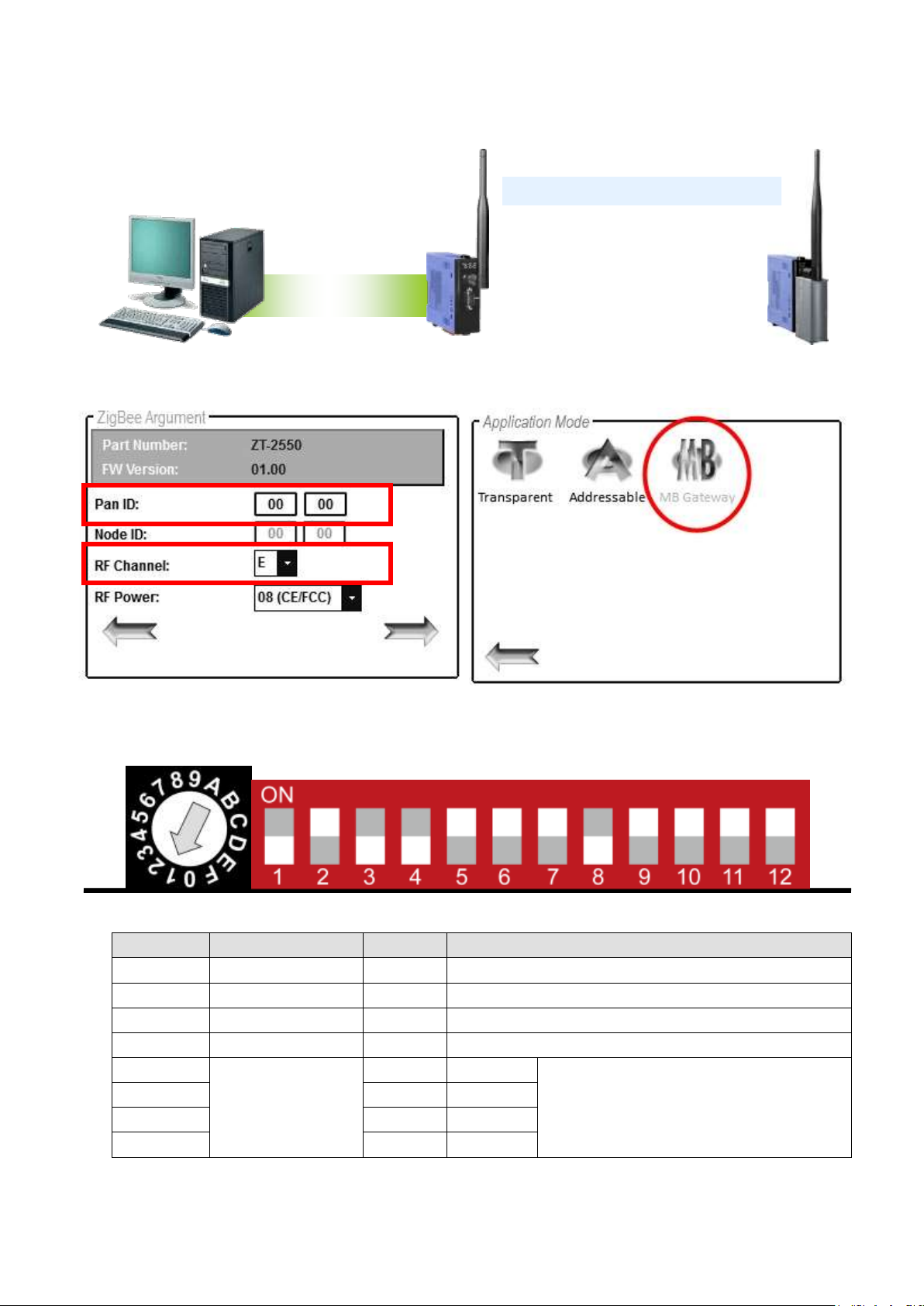
3.5 Examples
Architecture Diagram
Configuring the ZT-2550/ZT-2570
Configuring the ZT-2000 I/O device
Number
Item
Status
Description
1
Address MSB
OFF
Address/Node ID is 01 (Rotary Switch=1)
2
Protocol
ON
Use the Modbus RTU Protocol
3
Checksum
OFF
Disabled
4
ZB PID
OFF
ZigBee Pan ID=0x0000
5
ZB Channel
ON
0x08
ZigBee RF Channel = 0x0E
6
ON
0x04 7 ON
0x02 8 OFF
------
RS-232/RS-485
ICP DAS, ZT-2018/S AI Series User Manual, Version 1.0.1 Page 17
Copyright © 2013 by ICP DAS Co., Ltd. All Rights Reserved.
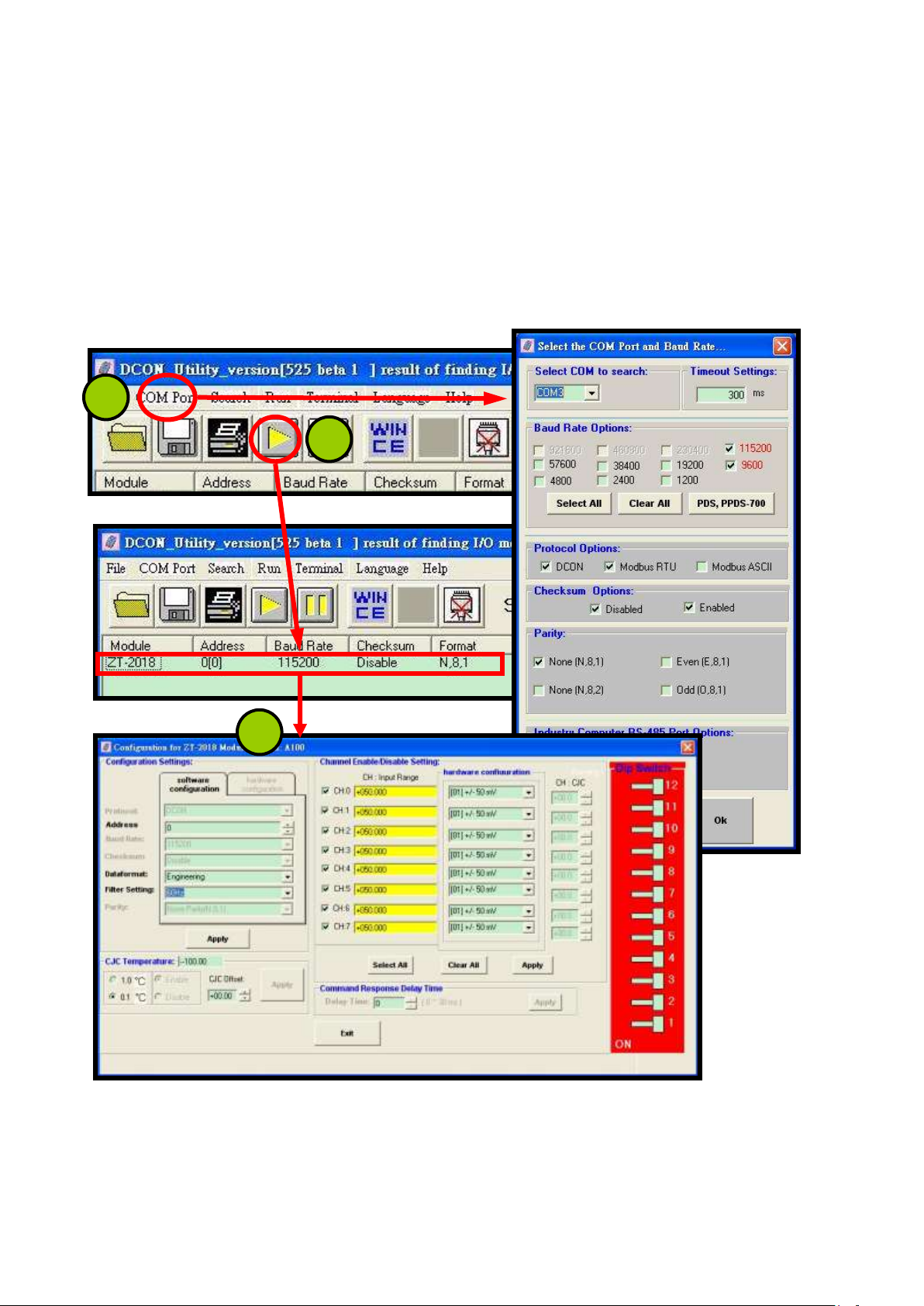
Simulating I/O channel operation via the DCON Utility
1. Launch the DCON Utility and select the appropriate COM Port settings to
connect to the ZigBee Coordinator (ZT-2550/ZT-2570).
2. Click the “Search” button to start searching for ZT-2000 I/O devices
connected to the same ZigBee network.
3. If any ZT-2000 I/O devices are found, they will be displayed in the device list
windows. Double-click the name of the name of the module to start the
operatiion.
2
3
1

ICP DAS, ZT-2018/S AI Series User Manual, Version 1.0.1 Page 18
Copyright © 2013 by ICP DAS Co., Ltd. All Rights Reserved.
4 Analog Input Type and Data Format
Type Code
Input Type
Data Format
+F.S.
-F.S.
00
-15 to +15
mV
Engineering Units
+15.000
-15.000
% of FSR*2
+100.00
-100.00
2’s Comp. Hex
7FFF
8000
01
-50 to +50
mV
Engineering Units
+50.000
-50.000
% of FSR*2
+100.00
-100.00
2’s Comp. Hex
7FFF
8000
02
-100 to +100
mV
Engineering Units
+100.00
-100.00
% of FSR*2
+100.00
-100.00
2’s Comp. Hex
7FFF
8000
03
-500 to +500
mV
Engineering Units
+500.00
-500.00
% of FSR*2
+100.00
-100.00
2’s Comp. Hex
7FFF
8000
04
-1 to +1
V
Engineering Units
+1.0000
-1.0000
% of FSR*2
+100.00
-100.00
2’s Comp. Hex
7FFF
8000
05
-2.5 to +2.5
V
Engineering Units
+2.5000
-2.5000
% of FSR*2
+100.00
-100.00
2’s Comp. Hex
7FFF
8000
06
-20 to +20
mA
Engineering Units
+20.000
-20.000
% of FSR*2
+100.00
-100.00
2’s Comp. Hex
7FFF
8000
07
4 to +20
mA
Engineering Units
+20.000
+04.000
% of FSR*2
+100.00
+000.00
2’s Comp. Hex
FFFF
0000
0E
Type J
Thermocouple
-210 ~ +760°C
Engineering Units
+760.00
-210.00
% of FSR*2
+100.00
-027.63
2’s Comp. Hex
FFFF
DCA2
0F
Type K
Thermocouple
-270 ~ +1372°C
Engineering Units
+1372.0
-0270.0
% of FSR*2
+100.00
-019.68
2’s Comp. Hex
7FFF
E6D0
10
Type T
Thermocouple
-270 ~ +400°C
Engineering Units
+400.00
-270.00
% of FSR*2
+100.00
-067.50
2’s Comp. Hex
7FFF
DCA2
11
Type E
Thermocouple
-270 ~ +1000°C
Engineering Units
+1000.0
-0270.0
% of FSR*2
+100.00
-027.00
2’s Comp. Hex
7FFF
DD71

ICP DAS, ZT-2018/S AI Series User Manual, Version 1.0.1 Page 19
Copyright © 2013 by ICP DAS Co., Ltd. All Rights Reserved.
12
Type R
Thermocouple
0 ~ +1768°C
Engineering Units
+1768.0
-0000.0
% of FSR*2
+100.00
-000.00
2’s Comp. Hex
7FFF
0000
13
Type S
Thermocouple
0 ~ +1768°C
Engineering Units
+1768.0
-0000.0
% of FSR*2
+100.00
-000.00
2’s Comp. Hex
7FFF
0000
14
Type B
Thermocouple
0 ~ +1820°C
Engineering Units
+1820.0
-0000.0
% of FSR*2
+100.00
-000.00
2’s Comp. Hex
7FFF
0000
15
Type N
Thermocouple
-270 ~ +1300°C
Engineering Units
+1300.0
-0270.0
% of FSR*2
+100.00
-020.77
2’s Comp. Hex
7FFF
E56B
16
Type C
Thermocouple
0 ~ +2320°C
Engineering Units
+2320.0
-0000.0
% of FSR*2
+100.00
-000.00
2’s Comp. Hex
7FFF
0000
17
Type L
Thermocouple
-200 ~ +800°C
Engineering Units
+800.00
-200.00
% of FSR*2
+100.00
-025.00
2’s Comp. Hex
7FFF
E000
18
Type M
Thermocouple
-200 ~ +100°C
Engineering Units
+100.00
-200.00
% of FSR*2
+050.00
-100.00
2’s Comp. Hex
4000
8000
19
Type LDIN43710
Thermocouple
-200 ~ +800°C
Engineering Units
+900.00
-200.00
% of FSR*2
+100.00
-022.22
2’s Comp. Hex
7FFF
E38E
1A
0 to +20
mA
Engineering Units
+20.000
+00.000
% of FSR*2
+100.00
+000.00
2’s Comp. Hex
FFFF
0000
*1: FSR (Full Scale Range)

ICP DAS, ZT-2018/S AI Series User Manual, Version 1.0.1 Page 20
Copyright © 2013 by ICP DAS Co., Ltd. All Rights Reserved.
Analog Input Over/Under Range Readings
Over Range
Under Range
Engineering Units
+9999.9
-9999.9
% of FSR
+999.99
-999.99
2’s Complement Hex
7FFF
8000
Analog Input Over/Under Range Readings when using the
Modbus RTU protocol
Over Range
Under Range
7FFFh
8000h
Data Format Settings (FF)
7 6 5 4 3 2 1
0
FS
Reserved
DF
Key
Description
DF
Data Format
00: Engineering Units
01: % of FSR
10: 2’s Complement Hexadecimal
FS
Filter Settings
0: 60 Hz Rejection
1: 50 Hz Rejection

ICP DAS, ZT-2018/S AI Series User Manual, Version 1.0.1 Page 21
Copyright © 2013 by ICP DAS Co., Ltd. All Rights Reserved.
5 Calibration
Warning
Performing calibration is not recommended until the process is fully understood.
The calibration procedure is as follows:
1. Warm up the module for at least 30 minutes.
2. Set the Type Code to the type you wish to calibrate. Refer to Section 4 and Section
6.2.13 for details.
3. Enable calibration. Refer to Section 6.2.31 for details.
4. Apply the zero calibration voltage/current.
5. Send the zero calibration command. Refer to Section 6.2.7 for details.
6. Apply the span calibration voltage/current.
7. Send the span calibration command. Refer to Section 6.2.6 for details.
8. Repeat steps 3 to 7 three times.
Notes
1. The calibration voltage/current source should be connected to channel 0.
2. Calibration voltages and currents are shown below.
3. Switch to DCON protocol mode before calibrating the module. Refer to Section 3.2
for details of how to switch protocols.
Calibration Voltage Types used by the ZT-2018/S
Type Code
00
01
02
03
04
05
06
Zero Input
0 mV
0 mV
0 mV
0 mV
0 V
0 V
0 mA
Span Input
+15 mV
+50 mV
+100 mV
+500 mV
+1 V
+2.5 V
+20 mA

ICP DAS, ZT-2018/S AI Series User Manual, Version 1.0.1 Page 22
Copyright © 2013 by ICP DAS Co., Ltd. All Rights Reserved.
6 The DCON/Modbus RTU Command Sets
6.1 Communicating with the ZT-2000 I/O Device
ICP DAS ZT-2000 I/O devices can be operated using either the DCON or the Modbus
RTU protocol, which can be selected by adjusting the position of DIP switch 2 to OFF
(DCON) or ON (Modbus RTU) and then rebooting the ZT-2000 I/O device to user the
new protocol.
6.2 The DCON Protocol Command Set
All ZT-2000 I/O series devices are controlled via wireless broadcast commands, so
each device must have a unique address that is saved in the EEPROM of the device.
Consequently, all command and response formats contain the address of the
destination module. When an I/O device receives a command, it will determine whether
or not to respond based on the address contained in the command. However, there are
two exceptions to this, the #** and ~** commands.
DCON Command Format
Delimiter
Character
Module
Address
Command
[CHECKSU
M]
CR
DCON Response Format
Delimiter
Character
Module
Address
Data
[CHECKSU
M]
CR
※ Note: ‘CR’ is the end of command (carriage return) character used to end a frame.
※ All characters should be expressed in capital letters.

ICP DAS, ZT-2018/S AI Series User Manual, Version 1.0.1 Page 23
Copyright © 2013 by ICP DAS Co., Ltd. All Rights Reserved.
6.2.1 Checksum
Calculating the Checksum:
Sum the ASCII codes of all the characters contained in the command in addition to the
‘CR’ terminator. The Checksum is the sum value expressed in Hexadecimal format.
Example: Command “$012(CR)”
Sum = ‘$’ + ‘0’ + ‘1’ + ‘2’ = 24h + 30h + 31h + 32h = B7h
Checksum = “B7”
DCON Command with Checksum =“$012B7(CR)”
Example: Response “!01200600(CR)”
Sum = ‘!’ + ‘0’ + ‘1’ + ‘2’ + ‘0’ + ‘0’ + ‘6’ + ‘0’ + ‘0’
= 21h+30h+31h+32h+30h+30h+36h+30h+30h
= 1AAh
Checksum = “AA”
DCON Response with Checksum = “!01200600AA(CR)”
※ Note: The Checksum is the sum value expressed in capital letters.

ICP DAS, ZT-2018/S AI Series User Manual, Version 1.0.1 Page 24
Copyright © 2013 by ICP DAS Co., Ltd. All Rights Reserved.
6.3 Overview of the DCON Command Set
General Command Set
Command
Response
Description
Section
%AANNTTCCFF
!AA
Sets the Configuration of the Module
6.2.3
#AA
>(Data)
Reads the Analog Input Data from all
Channels
6.2.4
#AAN
>(Data)
Reads the Analog Input Data from a
Specific Channel
6.2.5
$AA0
!AA
Performs an Analog Input Span
Calibration
6.2.6
$AA1
!AA
Performs an Analog Input Zero
Calibration
6.2.7
$AA2
!AANNTTCCFF
Reads the Configuration of the Module
6.2.8
$AA5
!AAS
Reads the Reset Status of the Module
6.2.10
$AA5VV
!AA
Enables or Disables Specific Analog
Input Channels
6.2.11
$AA6
!AAVV
Reads whether each Analog Input
Channel is Enabled or Disabled
6.2.12
$AA7CiRrr
!AA
Sets the Type Code for a Specific
Analog Input Channel
6.2.13
$AA8Ci
!AACiRrr
Reads the Type Code for a Specific
Analog Input Channel
6.2.14
$AAF
!AA(Data)
Reads the Firmware Version of the
Module
6.2.21
$AAM
!AA(Data)
Reads the Name of the Module
6.2.22
$AAS1
!AA
Reloads the Default Calibration
Parameters
6.2.23
~AAEV
!AA
Enables or Disables Calibration for the
Module
6.2.31
~AAO(Name)
!AA
Sets the Name of the Module
6.2.32
@AACH
!AA
Clears the High Latch Values for all
Analog Input Channels
6.2.33
@AACHi
!AA
Clears the High Latch Value for a
Specific Analog Input Channel
6.2.34
@AACHCi
!AA
Clears the Status of the High Alarm for
a Specific Analog Input Channel
6.2.35

ICP DAS, ZT-2018/S AI Series User Manual, Version 1.0.1 Page 25
Copyright © 2013 by ICP DAS Co., Ltd. All Rights Reserved.
@AACL
!AA
Clears the Low Latch Values for all
Analog Input Channels
6.2.36
@AACLi
!AA
Clears the Low Latch Value for a
Specific Analog Input Channel
6.2.37
@AACLCi
!AA
Clears the Status of the Low Alarm for
a Specific Analog Input Channel
6.2.38
@AADHCi
!AA
Disables the High Alarm for a Specific
Analog Input Channel
6.2.39
@AADI
!AAHHLL
Reads the Status of the Alarms for all
Analog Input Channels
6.2.40
@AADLCi
!AA
Disables the Low Alarm for a Specific
Analog Input Channel
6.2.41
@AAHI(Data)CiT
!AA
Sets the High Alarm Value and Type
for a Specific Analog Input Channel
6.2.42
@AALO(Data)CiT
!AA
Sets the Low Alarm Value and Type for
a Specific Analog Input Channel
6.2.43
@AARH
!AA(Data)
Reads the High Latch Values for all
Analog Input Channels
6.2.45
@AARHi
!AA(Data)
Reads the High Latch Value for a
Specific Analog Input Channel
6.2.46
@AARHCi
!AA(Data)S
Reads the High Alarm Value for a
Specific Analog Input Channel
6.2.47
@AARL
!AA(Data)
Reads the Low Latch Values for all
Analog Input Channels
6.2.48
@AARLi
!AA(Data)
Reads the Low Latch Value for a
Specific Analog Input Channel
6.2.49
@AARLCi
!AA(Data)S
Reads the Low Alarm Value for a
Specific Analog Input Channel
6.2.50

ICP DAS, ZT-2018/S AI Series User Manual, Version 1.0.1 Page 26
Copyright © 2013 by ICP DAS Co., Ltd. All Rights Reserved.
CJC Command Sets
Command
Response
Description
Section
$AA3
>(Data)
Reads the CJC Temperature
6.2.9
$AA9
!AA(Data)
Reads the CJC Offset Value
6.2.15
$AA9SNNNN
!AA
Sets the CJC Offset Value
6.2.16
$AA9Ci
!AA(Data)
Reads the CJC Offset Value for a
Specific Analog Input Channel
6.2.17
$AA9SNNNNCi
!AA
Sets the CJC Offset Value for a
Specific Analog Input Channel
6.2.18
$AAA
!AAi
Reads the CJC Temperature Update
Settings
6.2.19
$AAAi
!AA
Sets the CJC Temperature Update
Settings
6.2.20
~AAC
!AAN
Read whether the CJC Function is
Enabled or Disabled
6.2.29
~AACN
!AA
Enables or Disables the CJC Function
6.2.30
@AAOD
!AAS
Reads the Status of the CJC
Connection
6.2.44
Host Watchdog Command Sets
Command
Response
Description
Section
~**
No Response
The command to inform all module that
the Host is OK
6.2.24
~AA0
!AASS
Reads the Status of the Host
Watchdog
6.2.25
~AA1
!AA
Resets the Status of the Host
Watchdog Timeout
6.2.26
~AA2
!AAETT
Reads the Timeout Settings for the
Host Watchdog
6.2.27
~AA3ETT
!AA
Enables or Disables the Host
Watchdog and sets the Host Watchdog
Timeout Value
6.2.28
ICP DAS, ZT-2018/S AI Series User Manual, Version 1.0.1 Page 27
Copyright © 2013 by ICP DAS Co., Ltd. All Rights Reserved.
%AANNTTCCFF
Description
This command is used to set the configuration of a specific module.
Syntax
%AANNTTCCFF[CHECKSUM](CR)
%
Delimiter character
AA
The address of the module to be configured in hexadecimal format (00 to FF)
NN
The new address of the module in hexadecimal format (00 to FF)
TT
00 (Reserved)
CC
0A (Reserved)
FF
The command used to set the data format, checksum, and filter settings.
See Section 4 for details of the data format.
Response
Valid Command
!AA[CHECKSUM](CR)
Invalid Command
?AA[CHECKSUM](CR)
!
Delimiter character to indicate a valid command
?
Delimiter character to indicate an invalid command
AA
The address of the responding module in hexadecimal format (00 to FF)
There will be no response if the command syntax is incorrect, there is a
communication error, or there is no module with the specified ad dress.
Examples
Command
%0320000A80
Response
!03
In Normal mode, the address 0x20 is saved to the EEPROM and the data format for
module 03 is set to 80 (50 Hz rejection). The module returns a response indicating that
the command was successful.
Command
%0320000A80
Response
!20
In Software Configuration mode, the address 0x20 is saved to the EEPROM and the
data format for module 03 is set to 80 (50 Hz rejection). The module returns a
response indicating that the command was successful.
Command
%0303000000
Response
?03
Attempts to set the configuration for module 03, but returns a response indicating
that an error occurred because the “CC”parameter must be 0A.
※Related Commands: Section 6.2.8 $AA2
※Related Topics: Section 4 Analog Input Type and Data Format
ICP DAS, ZT-2018/S AI Series User Manual, Version 1.0.1 Page 28
Copyright © 2013 by ICP DAS Co., Ltd. All Rights Reserved.
6.3.1 #AA
Description
This command is used to read data from all the Analog Input channels of a specified
module.
Syntax
#AA[CHECKSUM](CR)
#
Delimiter character
AA
The address of the module to be read in hexadecimal format (00 to FF)
Response
Valid Command
>(Data)[CHECKSUM](CR)
Invalid Command
?AA[CHECKSUM](CR)
>
Delimiter character to indicate a valid command
?
Delimiter character to indicate an invalid command
AA
The address of the responding module in hexadecimal format (00 to FF)
(Data)
The data from all the Analog Input channels. See Section 4 for details of the
data format. Data from disabled channels is filled with space characters.
There will be no response if the command syntax is incorrect, there is a
communication error, or there is no module with the specified address.
Examples
Command
#03
Response
>+15.000+15.000+15.000+15.000+15.000+15.000+15.000+15.000
Reads data from the Analog Input channels of module 03 and returns a response
indicating that the command was successful, with the data from all Analog Input
channels in engineering units format.
Command
#03
Response
>-9999.9-9999.9-9999.9-9999.9-9999.9-9999.9
Attempts to read data from the Analog Input channels of module 03, but returns a
response indicating that the command was unsuccessful because the data is not
within the valid range.
※Related Commands: Section 6.2.3 %AANNTTCCFF, Section 6.2.8 $AA2, Section 6.2.13
$AA7CiRrr
※Related Topics: Section 4 Analog Input Type and Data Format.
Section 7.1 Software Configuration Mode

ICP DAS, ZT-2018/S AI Series User Manual, Version 1.0.1 Page 29
Copyright © 2013 by ICP DAS Co., Ltd. All Rights Reserved.
6.3.2 #AAN
Description
This command is used to read data from a specific Analog Input channel of a specified
module.
Syntax
#AAN[CHECKSUM](CR)
#
Delimiter character
AA
The address of the module to be read in hexadecimal format (00 to FF)
N
The Analog Input channel to be read, zero based
Response
Valid Command
>(Data)[CHECKSUM](CR)
Invalid Command
?AA[CHECKSUM](CR)
>
Delimiter character to indicate a valid command
?
Delimiter character to indicate an invalid command.
AA
The address of the responding module in hexadecimal format (00 to FF)
(Data)
The data from the specified Analog Input channel. See Section 4 for details
of the data format. If the specified channel is disabled, then the data field
will be filled with space characters.
There will be no response if the command syntax is incorrect, there is a
communication error, or there is no module with the specified address.
Examples
Command
#032
Response
>+025.13
Reads data from Analog Input channel 2 of module 03 and returns a response
indicating that the command was successful, and the Analog Input value is +025.13
(+25.13mV).

ICP DAS, ZT-2018/S AI Series User Manual, Version 1.0.1 Page 30
Copyright © 2013 by ICP DAS Co., Ltd. All Rights Reserved.
Command
#039
Response
?03
Attempts to read data from Analog Input channel 9 of module 03, but returns a
response indicating that the command was unsuccessful because Analog Input
channel 9 does not exist.
※Related Commands: Section 6.2.3 %AANNTTCCFF, Section 6.2.8 $AA2, Section 6.2.13
$AA7CiRrr
※Related Topics: Section 4 Analog Input Type and Data Format.
Section 7.1 Software Configuration Mode
 Loading...