


Product #:ZB-UPH01
ZB-UPH01
ZigBee T ransceiver Module
User Manual
Version 0.9
Confidential Page 1/14
Doc. #: ZB-UPH01 Reference Note <Rev. 0.9>

Product #:ZB-UPH01
TABLE OF CONTENTS
1 GENERAL INFORMATION… ……………….……………..…….…3
2 POWER SAVING MODES …………………….……….…………….4
3 CONNECTORS PIN CONFIGURATION … …….….….….……….5
4 ELECTRICAL SPECIFICATIONS ……………..…………………...6
5 DESIGN GUIDE TO AVOID RF INTERFERENCE …………….....7
6 RF PERFORMANCE TEST DATA …………………….….…….…..10
7 REFERENCE REFLOW TEMPETURE CURVE…………………..11
8 REFERENCE DOCUMENTS………..…………………..…………...11
Confidential Page 2/14
Doc. #: ZB-UPH01 Reference Note <Rev. 0.9>

Product #:ZB-UPH01
Revised Date: Apr.14, 2010
1. GENERAL INFORMATION
The ZB-UPH01 is a miniature 2.4 GHz Direct Sequence Spread Spectrum 802.15.4 transceiver. It
includes all RF hardware and a micro-controller to manage the communications link. The
micro-controller manages all communications task including configuration, data packaging, and
clear channel selection. The result is a complete wireless data communications solution.
The ZB-UPH01 package is unique because of its small form factor (32 x 23 mm2), It has an
on-board chip antenna and the availability of external dipole antenna I-PEX connector. No
competitive products can offer a solution as flexible, convenient, and easy to integrate.
Models
• ZB-UPH01: Same as ZB-UPH01 but adding external SRAM
Features
• 32 x 23 mm2 PCBA package with 2 connectors
• Utilizes globally available 2.4 GHz ISM band
• Programmable Transmit Power Output, max. 9dBm.
• Complete IEEE 802.15.4 Spec. compliant.
• Typical Receiver Sensitivity –101dBm.
• Typical Data Rate 250Kbps.
• Multiple Low Power Operating modes
• Meet RoHS Requirement
Confidential Page 3/14
Doc. #: ZB-UPH01 Reference Note <Rev. 0.9>

Product #:ZB-UPH01
2. POWER SAVING MODES
The ZB-UPH01 includes several low power operating modes to permit the most efficient use of the
available power. Below are descriptions of the available selections.
ACTIVE: In Active Mode, all ZB-UPH01 circuits are powered and available for immediate action.
This includes the RF receiver which actively monitors the air for an incoming communications
request. Two sub-modes are classified as TX-ACTIVE and RX-ACTIVE. The current
consumption of TX-ACTIVE is 44 mA while RX-ACTIVE is 38 mA.
Confidential Page 4/14
Doc. #: ZB-UPH01 Reference Note <Rev. 0.9>
Product #:ZB-UPH01
3. CONNECTORS PIN CONFIGURATION
ZB-UPH01 uses Silicon-Lab C8051F340 as MCU. It is an 8051 base MCU and reserves 10 GPIO
pins for external controlling by application. Each pin can be a general I/O pin and programmed it
by user directly. Furthermore, most of these pins can be used as special purpose function. Thereof
TX, RX pins can be programmed as UART for data communication. For example, user is easy to
connect these pins with RS485 transceivers such as 75176, MAX485.
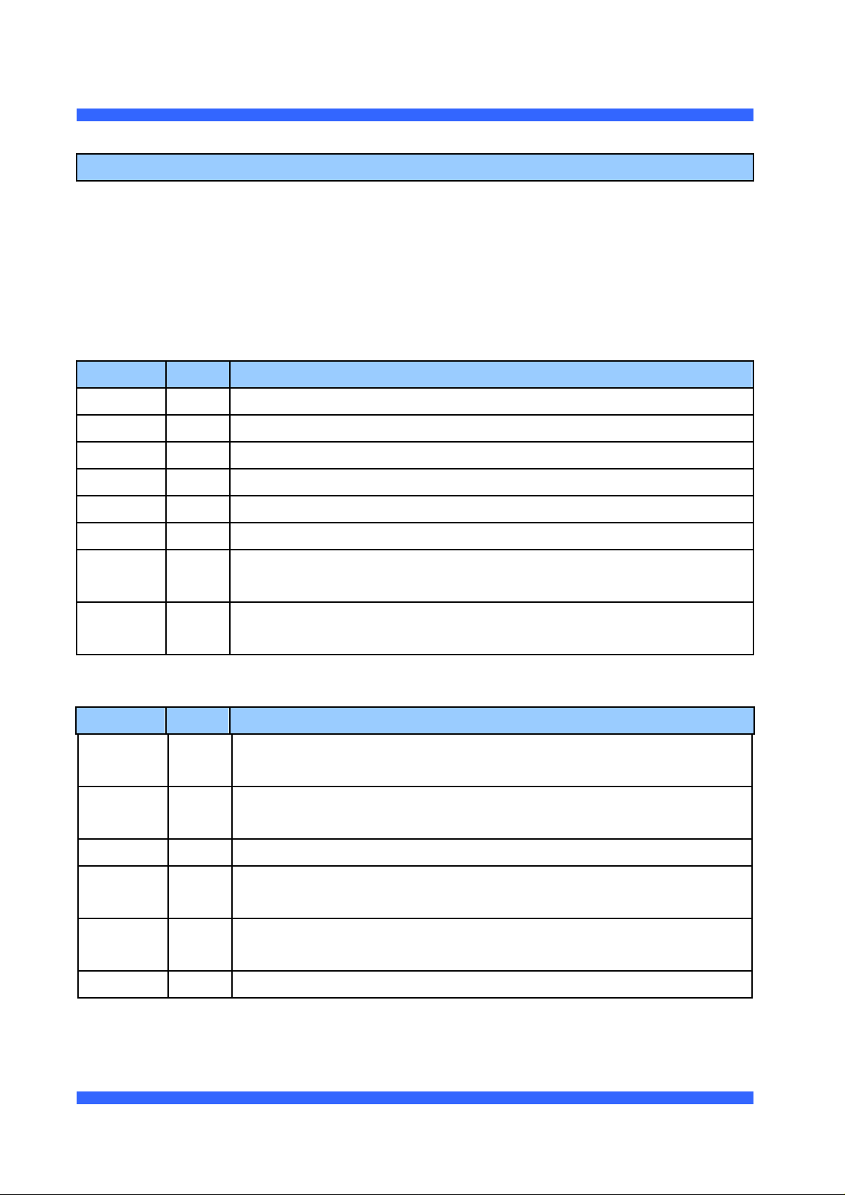
J1 Pin Configuration
Signal Pin Description
C2CK 1 Clock signal for the C2 Debug Interface.
C2D 2 Bi-directional data signal for the C2 Debug Interface.
VCC 3 3.3 Volt power for the ZB-UPH01
TX 4 GPIO, also used as UART TX.
GND 5 Ground
RX 6 GPIO, also used as UART RX.
GPIO1 7 Bidirectional input/output Pin. It also can be programmed as analog to
digital converter (ADC1)
GPIO2 8 Bidirectional input/output Pin. It also can be programmed as analog to
digital converter (ADC2)
J2 Pin Configuration
Signal Pin Description
GPIO3 1 Bidirectional input/output Pin. It also can be programmed as analog to
digital converter (ADC3)
GPIO4 2 Bidirectional input/output Pin. It also can be programmed as analog to
digital converter (ADC4)
GPIO5 3 Bidirectional input/output Pin.
GPIO6 4 Bidirectional input/output Pin. It also can be programmed as analog to
digital converter (ADC5)
GPIO7 5 Bidirectional input/output Pin. It also can be programmed as analog to
digital converter (ADC6)
GPIO8 6 Bidirectional input/output Pin.
Confidential Page 5/14
Doc. #: ZB-UPH01 Reference Note <Rev. 0.9>

Product #:ZB-UPH01
4. ELECTRICAL SPECIFICATIONS
Absolute Maximum Rating
VCC 3.6V
Storage temperature -40°C to +120°C
Operating temperature Range -30°C to +80°C
WARNING: Exceeding any of these ratings will void the warranty and may damage the device
Parameters Min Typ Max Units
Supply Voltage for RF, analog and digital circuits 3 3.3 3.6 V
Digital I/O Pin Input High Voltage 2.0 V
Digital I/O Pin Input Low Voltage 0.8 V
Analog Input Pin Input Voltage 0 3.3 V
I/O Pin Output High Current 4 8 mA
I/O Pin Output Low Current 8 14 mA
I/O Pin Input High Current 0 10 uA
I/O Pin Input Low Current 0 10 uA
Current Consumption
ACTIVE TX Mode @ 9 dBm 44 mA
ACTIVE RX Mode 38 mA
Output Power 9 dBm
Wireless Receive Sensitivity -101 dBm
Selectable Channels 16 channel
Frequency Band 2.400 2.835 GHz
Antenna Output Impedance 50 Ohms
Confidential Page 6/14
Doc. #: ZB-UPH01 Reference Note <Rev. 0.9>

Product #:ZB-UPH01
5. DESIGN GUIDE TO AVOID RF INTERFERENCE
When RF module put on an application board(mother board), to minimize the RF signal
interference, the best way is to define an isolation area. This area should have no any trace or
grounding pad. Here are some layout suggestions for mother board.
Suggestion 1: Place RF board aside mother board. (Let antenna part outside mother board is
better) Make sure no trace and grounding pad under the must isolate area. Please see the drawing
as below.
Must Isolate Area
Prefer Isolate Area
Module Board
Via
Mother Board
Antenna
Suggestion 2: Place RF board at the corner of mother board. Make sure no trace and
grounding pad under the must isolate area. Please see the drawing as below.
Must Isolate Area
Prefer Isolate Area
RF Module Board
Via
Customer's Mother Board
Antenna
Confidential Page 7/14
Doc. #: ZB-UPH01 Reference Note <Rev. 0.9>

Product #:ZB-UPH01
Suggestion 3: If you couldn’t put RF board at one side or at the corner of mother board. You
must make sure no circuit trace and grounding pad under the must isolate area, and at least reserve
extra 3 mm space as safety area. Please see the drawing as below.
Must Isolate Area
Prefer Isolate Area
RF Module Board
Via
Customer's Mother Board
Antenna
For all of above suggestions, try to extend isolation area from must area to prefer area. Please
see the drawing as below. The more isolation area, the better RF performance。
Must Isolate Area
Prefer Isolate Area
RF Module Board
Via
Customer's Mother Board
Antenna
Confidential Page 8/14
Doc. #: ZB-UPH01 Reference Note <Rev. 0.9>

Product #:ZB-UPH01
Must Isolate Area
Prefer Isolate Area
RF Module Board
Via
Customer's Mother Board
Antenna
Confidential Page 9/14
Doc. #: ZB-UPH01 Reference Note <Rev. 0.9>

Product #:ZB-UPH01
6. RF PERFORMANCE TEST DATA
Return Loss: -17.5dB
Confidential Page 10/14
Doc. #: ZB-UPH01 Reference Note <Rev. 0.9>

Product #:ZB-UPH01
7. REFERENCE REFLOW TEMPETURE CURVE
Confidential Page 11/14
Doc. #: ZB-UPH01 Reference Note <Rev. 0.9>

Product #:ZB-UPH01
8. Reference Documents
13.1 UBEC UZ2400 datasheet
13.2 UBEC UP2268 datasheet
13.3 ACX A T5020 datasheet
Confidential Page 12/14
Doc. #: ZB-UPH01 Reference Note <Rev. 0.9>

Product #:ZB-UPH01
Federal Communication Commission Interference Statement
This equipment has been tested and found to comply with the limits for a Class B digital device,
pursuant to Part 15 of the FCC Rules. These limits are designed to provide reasonable protection
against harmful interference in a residential installation. This equipment generates, uses and can
radiate radio frequency energy and, if not installed and used in accordance with the instructions, may
cause harmful interference to radio communications. However, there is no guarantee that interference
will not occur in a particular installation. If this equipment does cause harmful interference to radio or
television reception, which can be determined by turning the equipment off and on, the user is
encouraged to try to correct the interference by one of the following measures:
● Reorient or relocate the receiving antenna.
● Increase the separation between the equipment and receiver.
● Connect the equipment into an outlet on a circuit different from that to which the receiver is
connected.
● Consult the dealer or an experienced radio/TV technician for help.
FCC Caution: Any changes or modifications not expressly approved by the party responsible for
compliance could void the user’s authority to operate this equipment.
This device complies with Part 15 of the FCC Rules. Operation is subject to the following two conditions:
(1) This device may not cause harmful interference, and (2) this device must accept any interference
received, including interference that may cause undesired operation.
This device and its antenna(s) must not be co-located or operation in conjunction with any other
antenna or transmitter.
Confidential Page 13/14
Doc. #: ZB-UPH01 Reference Note <Rev. 0.9>

Product #:ZB-UPH01
IMPORTANT NOTE:
This module is intended for OEM integrator. The OEM integrator is still responsible for the FCC
compliance requirement of the end product, which integrates this module.
Any changes or modifications not expressly approved by the manufacturer could void the user's
authority to operate this equipment.
USERS MANUAL OF THE END PRODUCT:
In the users manual of the end product, the end user has to be informed to keep at least 20cm
separation with the antenna while this end product is installed and operated. The end user has to be
informed that the FCC radio-frequency exposure guidelines for an uncontrolled environment can be
satisfied. The end user has to also be informed that any changes or modifications not expressly
approved by the manufacturer could void the user's authority to operate this equipment. If the size of
the end product is smaller than 8x10cm, then additional FCC part 15.19 statement is required to be
available in the users manual: This device complies with Part 15 of FCC rules. Operation is subject to
the following two conditions: (1) this device may not cause harmful interference and (2) this device must
accept any interference received, including interference that may cause undesired operation.
LABEL OF THE END PRODUCT:
The final end product must be labeled in a visible area with the following " Contains TX FCC ID:
Q6MZBUPH0001 ". If the size of the end product is larger than 8x10cm, then the following FCC part
15.19 statement has to also be available on the label: This device complies with Part 15 of FCC rules.
Operation is subject to the following two conditions: (1) this device may not cause harmful interference
and (2) this device must accept any interference received, including interference that may cause
undesired operation.
Confidential Page 14/14
Doc. #: ZB-UPH01 Reference Note <Rev. 0.9>
 Loading...