

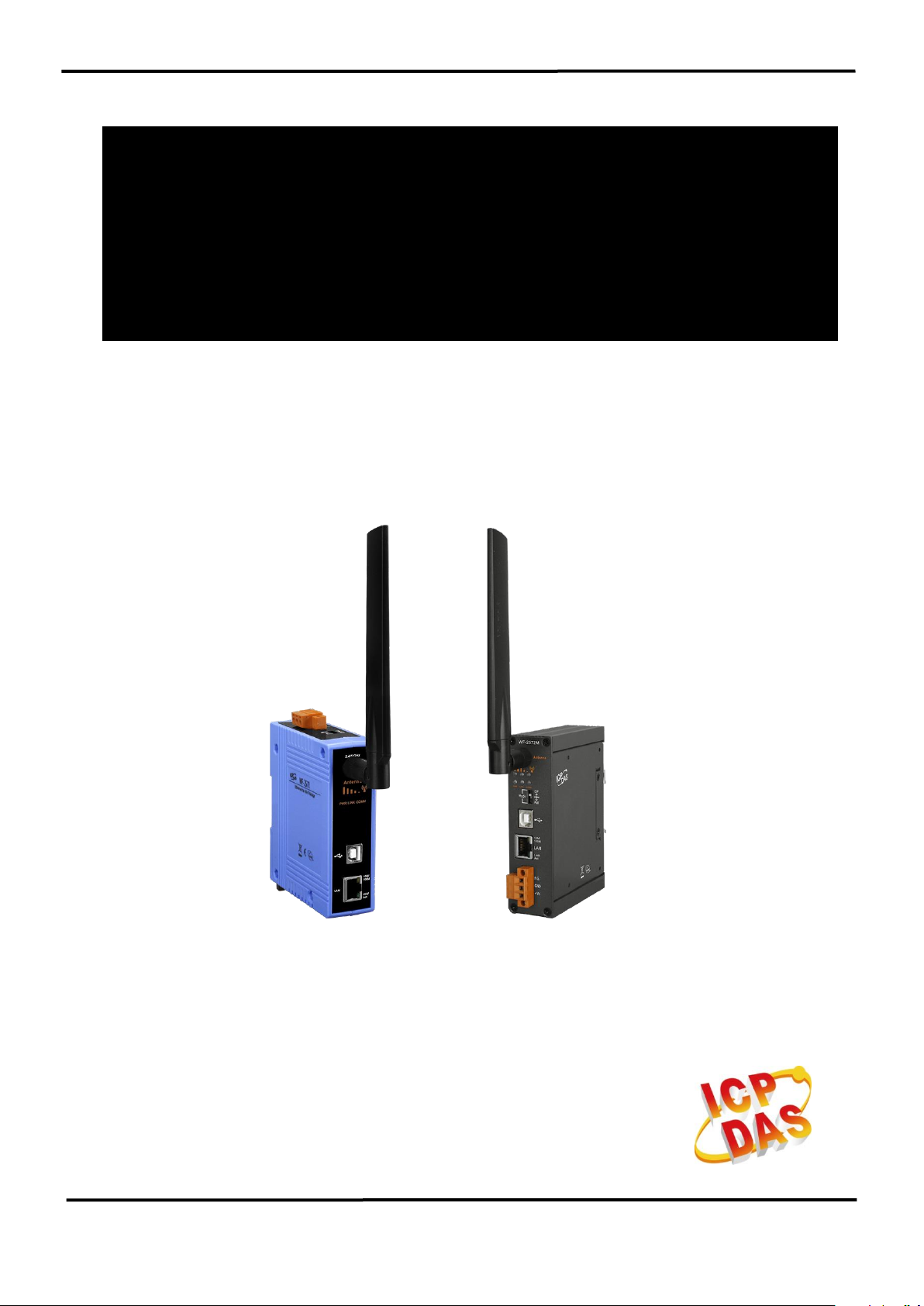
WF-2572/WF-2572M
Ethernet to Wi-Fi Bridge
User Manual v1.10
www.icpdas.com
WF-2572 Series, Ethernet to Wi-Fi Bridge (V1.10, 2019/08/30) 1

Version
Date
Note
1.00
2018/09/30
Release version
1.10
2018/08/30
Add WF-2572M of feature
Information
Warranty_______________________________________________________
All products manufactured by ICP DAS are under warranty regarding
defective materials for a period of one year from the date of delivery to the
original purchaser.
Waring_______________________________________________________
ICP DAS assumes no liability for damages resulting from the use of this
product. ICP DAS reserves the right to change this manual at any time without
notice. The information furnished by ICP DAS is believed to be accurate and
reliable. However, no responsibility is assumed by ICP DAS for its use, or for any
infringements of patents or other rights of third parties resulting from its use.
Copyright_______________________________________________________
Copyright 2018 by ICP DAS. All rights are reserved.
Trademark______________________________________________________
The names used for identification only may be registered trademarks of their
respective companies.
Technical Support_______________________________________________
If you have any problems, feel free to contact us via e-mail at
service@icpdas.com
Document Revision
WF-2572 Series, Ethernet to Wi-Fi Bridge (V1.10, 2019/08/30) 2

Content
1. INTRODUCTION ..................................................................................................................................... 5
1.1 FEATURE .................................................................................................................................................. 6
1.2 UTILITY .................................................................................................................................................... 6
2. HARDWARE ............................................................................................................................................ 7
2.1 SPECIFICATIONS ....................................................................................................................................... 7
2.2 WF-2572 SERIES APPEARANCE ................................................................................................................ 8
2.2.1 Front Panel of WF-2572 ..................................................................................................................... 8
2.2.2 Front Panel of WF-2572M.................................................................................................................. 9
2.2.3 Top Panel .......................................................................................................................................... 10
2.2.4 LED Indicator ................................................................................................................................... 11
2.3 POWER WIRE CONNECTION ..................................................................................................................... 12
2.4 WATCHDOG TIMER SETTING .................................................................................................................. 12
2.5 FW / OP DIP-SWITCH ............................................................................................................................. 12
2.5.1 Firmware update mode ..................................................................................................................... 12
2.5.2 Firmware Operation Mode ............................................................................................................... 14
2.6 DIMENSIONS ........................................................................................................................................... 14
2.6.1 Dimensions of WF-2572 ................................................................................................................... 14
2.6.2 Dimensions of WF-2572M ................................................................................................................ 15
3. SOFTWARE ........................................................................................................................................... 16
3.1 WIRELESS CONFIGURATION TOOL – WF-2572 UTILITY ......................................................................... 16
3.2 WF-2572 UTILITY .................................................................................................................................. 16
3.3.1 Wi-Fi Parameter ............................................................................................................................... 17
3.3.2 Device MAC ...................................................................................................................................... 17
3.3.3 IP Setting .......................................................................................................................................... 18
4. APPLICATION SETTING ..................................................................................................................... 18
4.1 SYSTEM ARCHITECTURE OF INFRASTRUCTURE MODE ............................................................................ 18
4.2 SYSTEM ARCHITECTURE OF LIMIT-AP MODE ........................................................................................ 19
4.3 HARDWARE INSTALLATION .................................................................................................................... 20
4.4 INFRASTRUCTURE SETTING DESCRIPTION .............................................................................................. 20
4.4.1 Test Architecture ............................................................................................................................... 20
4.4.2 Setting step ........................................................................................................................................ 21
4.4.3 Query device MAC by using WF-2572 utility ................................................................................... 22
4.5 LIMIT-AP MODE .................................................................................................................................... 24
WF-2572 Series, Ethernet to Wi-Fi Bridge (V1.10, 2019/08/30) 3

4.5.1 Test Architecture ............................................................................................................................... 24
4.5.2 Setting step ........................................................................................................................................ 24
5. TECHNICAL SUPPORT........................................................................................................................ 26
WF-2572 Series, Ethernet to Wi-Fi Bridge (V1.10, 2019/08/30) 4
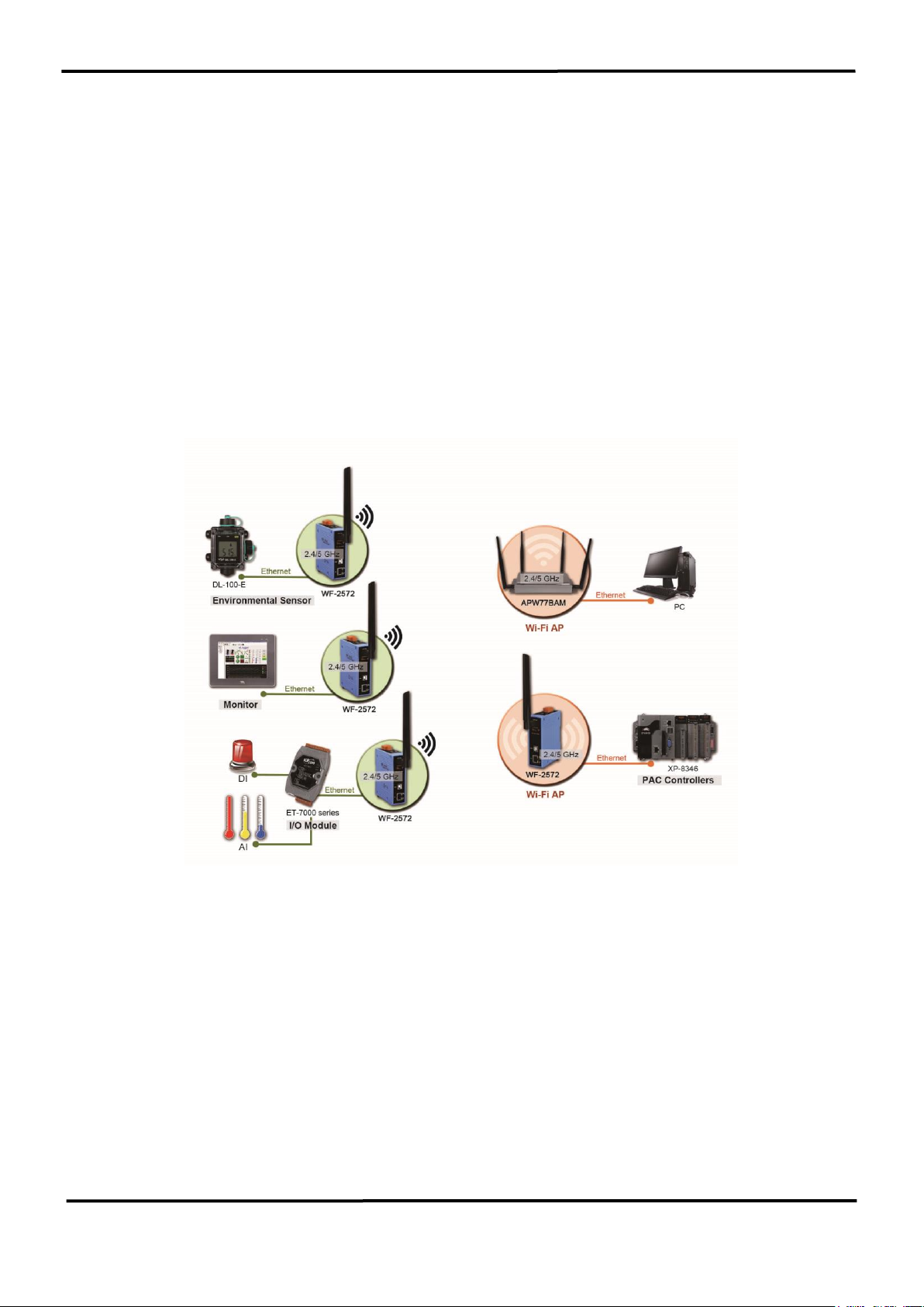
1. Introduction
The WF-2572/WF-2572M is an industrial Ethernet to Wi-Fi Bridge. The device only
needs to connect the Ethernet cable with WF-2572/WF-2572M that can create an IEEE 802.11
a/b/g wireless personal network. The interface between Ethernet and Wi-Fi use transparent
transmission so that it can convert Wi-Fi to wire internet without complex settings. The WF2572/WF-2572M also supports dual bands (2.4/5 GHz). The 2.4 GHz is more crowded than 5
GHz. Therefore, the devices on 2.4 GHz suffer much more interference than the ones on 5 GHz.
The WF-2572/WF-2572M has less interference on 5 GHz.
Figure 1-1. The application architecture of WF-2572
WF-2572 Series, Ethernet to Wi-Fi Bridge (V1.10, 2019/08/30) 5
1.1 Feature
Frequency: 2.4/5 GHz
Full compatible with IEEE 802.11 a/b/g
Support Wi-Fi Limit-AP and Infrastructure mode
Support WPA-PSK, WPA2-PSK for Wi-Fi encryption
Plug-and-Play Ethernet to Wi-Fi connectivity
USB-based configuration
No driver installation required
Built-in Watchdog
Metal case(WF-2572M)
Extended operating temperature range (-25°C ~ +75°C)
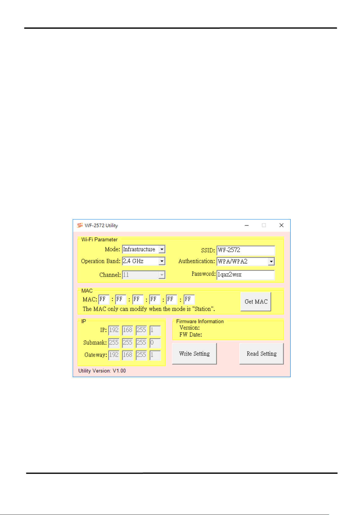
1.2 Utility
Configuration by USB interface
Support setting of Wi-Fi Infrastructure and Limit-AP mode
Figure 1-2. WF-2572 Utility
WF-2572 Series, Ethernet to Wi-Fi Bridge (V1.10, 2019/08/30) 6

Item
WF-2572
WF-2572M
RF Specification
Standard
IEEE 802.11 a/b/g
Frequency
2.4 GHz: CH1~11
5 GHz: CH36、40、44、48
Operation mode
Limit-AP / Infrastructure
Encryption
Open/WPA/WPA2
Antenna
Omni-Directional
3 dBi @ 2.4 GHz
5.5 dBi @ 5 GHz
Transmission Range
50 m (LOS)
Ethernet
Controller
100Base-TX Ethernet Controller (Auto-MDIX)
Connector
RJ-45 with LED indicator
USB Interface
Type
USB 2.0 Full-Speed
Connector
USB type B
LED Indicator
System status
3 Indicator LEDs (PWR, LINK, COMM)
Signal strength
3 Indicator LEDs (High, Mid, Low)
Power
Input Voltage Range
10 ~ 30VDC
Power Consumption
1.6 W
Mechanism
Casing
Plastic
Metal
Installation
DIN-Rail
Dimensions
33mm x 95mm x 120mm
(W x L x H)
33mm x 108mm x 120mm
(W x L x H)
Environment
Operation Temp.
-25℃ ~ +75℃
Storage Temp.
-30℃ ~ +80°C
Humidity
10~90%
2. Hardware
2.1 Specifications
WF-2572 Series, Ethernet to Wi-Fi Bridge (V1.10, 2019/08/30) 7
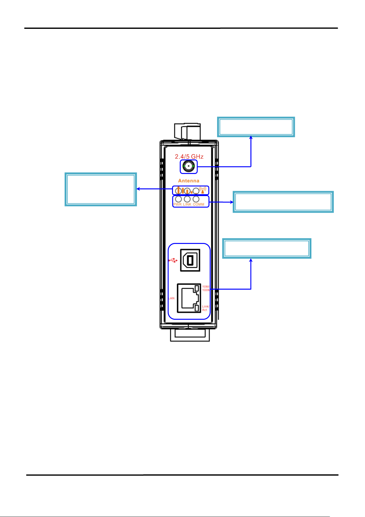
RP SMA Connector
USB/Ethernet Connector
LED Indicator
System Status LED Indicator
2.2 WF-2572 Series Appearance
2.2.1 Front Panel of WF-2572
The WF-2572 front panel contains the antenna, USB connector, Ethernet connector and
LEDs.
Signal Strength
Figure 2-1. Front Panel of the WF-2572
WF-2572 Series, Ethernet to Wi-Fi Bridge (V1.10, 2019/08/30) 8

Power Connector
Pin Assignment
Description
F.G
Frame Ground
GND
Power GND
+Vs
+10 ~ +30 VDC
RP SMA Connector
Signal Strength
LED Indicator
System Status LED Indicator
Operating mode
selector switch
USB/Ethernet Connector
Power Connector
2.2.2Front Panel of WF-2572M
The WF-2572M front panel contains the antenna, USB connector, Ethernet connector
Power connector, operating mode selector switch and LEDs.
Figure 2-2. Front Panel of the WF-2572
Table 2-1. Power Connector
WF-2572 Series, Ethernet to Wi-Fi Bridge (V1.10, 2019/08/30) 9

Power Connector
Pin Assignment
Description
F.G
Frame Ground
GND
Power GND
+Vs
+10 ~ +30 VDC
Operating mode
selector switch
Power Connector
2.2.3 Top Panel
The WF-2572 top panel contains the power connector and operating mode selector switch.
FW mode: Firmware update mode
OP mode: Firmware operation mode
11
Figure 2-3. Top Panel of WF-2572
Table 2-2. Power Connector
WF-2572 Series, Ethernet to Wi-Fi Bridge (V1.10, 2019/08/30) 10

LED
LED Status
Description
Limit-AP mode
Signal strength-Green
Always ON
Device at Limit-AP mode
Signal strength-Yellow
Always ON
AP at 2.4 GHz
OFF
AP at 5 GHz
Power (PWR)
Always ON
Power Good
OFF
Power failure
Connection Status(LINK)
Blink/Always ON
Unconnected
OFF
Connected
Communication(COMM)
Blink
Data transmission
OFF
Bus Idle
Infrastructure mode
Signal strength
Signal strength: High
Signal strength: Medium
Signal strength: Low
Unconnected
Power (PWR)
Always ON
Power Good
OFF
Power failure
Connection Status(LINK)
Blink/Always ON
Unconnected
OFF
Connected
Communication(COMM)
Blink
Data transmission
OFF
Bus Idle
2.2.4 LED Indicator
The LED Indicator can be divided into two types. The one is signal strength indicator. The
other is system status indicator. The description of the LED indicator as shown in Table 2-3.
Table 2-3. The description of LED indicator
WF-2572 Series, Ethernet to Wi-Fi Bridge (V1.10, 2019/08/30) 11

2.3 Power wire connection
The power wire connection of WF-2572 has shown in Figure 2-4.
Figure 2-4. Power wire connection of WF-2572
2.4 Watchdog Timer Setting
A watchdog timer (WDT) is a device that performs a specific operation after a certain
period of time if something goes wrong and the system does not recover on its own. A
watchdog timer can perform a warm boot (restarting the system) after a certain number of
milliseconds.
The WF-2572 supplies a jumper for users to active the watchdog timer or not. Inside the
WF-2572 users can use the JP1 to activate the WDT built in the module, as the Figure 2-5. Note
that the default setting is active.
Figure 2-5. Watchdog Setting
2.5 FW / OP Dip-switch
On the top of the WF-2572 series module, there is a dip-switch used for firmware
operation or firmware update modes selection of the module.
2.5.1 Firmware update mode
As shown in Figure 2-6, it need to set the dip-switch to the “FW” position after that the
WF-2572 will work in the “Firmware Update Mode” after reset the power. In this mode, users
WF-2572 Series, Ethernet to Wi-Fi Bridge (V1.10, 2019/08/30) 12

Figure 2-6. FW update position of Dip-Switch
Figure 2-7. USB Mass Storage Device
1
2
3
4
can update the firmware of the WF-2572 via USB interface and it will become a “USB Mass
Storage Device” and shows a folder automatically.
Users just need to execute “Firmware_Update_Tool.exe” and follow the below steps
to complete the firmware updating process.
Step1. Choose “USB” interface and “USB Disk”.
Step2. Click “Browser” button to choose firmware file. (e.g. WF2572_V100.fw)
Step3. Click “Firmware Update” button to start firmware updating process.
The result will be showing in “Firmware Update” field.
The WF-2572 firmware can be downloaded from
ftp://ftp.icpdas.com/pub/cd/usbcd/napdos/wifi/WF-2572/firmware/
Figure 2-8. WF-2572 firmware update process
WF-2572 Series, Ethernet to Wi-Fi Bridge (V1.10, 2019/08/30) 13

Left Side View
Front View
The Firmware_Update_Tool can be downloaded from
ftp://ftp.icpdas.com/pub/cd/usbcd/napdos/wifi/WF-2572/software/tool/
2.5.2 Firmware Operation Mode
As shown in Figure 2-9, Users need to set the dip-switch to the “OP” position and reset the
power, which the WF-2572 can run in the operation mode. In this mode, user can use the WF2572 with a computer or other devices that have Ethernet interface for wireless connection.
Figure 2-9. OP Position of Dip-Switch
2.6 Dimensions
The diagrams below provide the dimensions of the WF-2572 series to use in defining your
enclosure specifications. All dimensions are in millimeters.
2.6.1 Dimensions of WF-2572
Figure 2-10. Front / Left side dimension of the WF-2572
WF-2572 Series, Ethernet to Wi-Fi Bridge (V1.10, 2019/08/30) 14

Top View Bottom View
Left ViewFront View
Right View Rear View
Figure 2-11. Top / Bottom side dimension of the WF-2572
2.6.2 Dimensions of WF-2572M
Figure 2-12. Front / Left side dimension of the WF-2572M
Figure 2-13. Right / Rear side dimension of the WF-2572M
WF-2572 Series, Ethernet to Wi-Fi Bridge (V1.10, 2019/08/30) 15

Wi-Fi Parameter
Device MAC
IP Setting
3. Software
This chapter explains how to use the WF-2572 Utility to carry on the WF-2572 wireless
communication configuration.
3.1 Wireless Configuration Tool – WF-2572 Utility
WF-2572 utility is a Microsoft Windows application that compatibles with Microsoft
Windows XP, 7 and 10.
The WF-2572 Utility can be downloaded from
ftp://ftp.icpdas.com/pub/cd/usbcd/napdos/wifi/wf-2572/software/utility/
3.2 WF-2572 Utility
The main screen of WF-2572 utility has shown in Figure 3-1; Users can configure the
wireless communication settings via this interface.
Figure 3-1. WF-2572 Utility
WF-2572 Series, Ethernet to Wi-Fi Bridge (V1.10, 2019/08/30) 16

Wi-Fi Parameter
Description
Mode
The Wi-Fi role of WF-2572.
The Wi-Fi role consists of Station (Infrastructure) and AP
(Limit-AP).
SSID
Wi-Fi SSID
1. It can set the AP’s SSID when the mode is “Limit-AP”.
2. The SSID mean that the Wi-Fi AP which WF-2572 would
like to connect when the mode is “Infrastructure”.
* Connected devices must be with the same SSID
Operation Band
The operation band of WF-2572.
The WF-2572 supports 2.4/5 GHz.
Authentication
The encryption of WF-2572
Encryption of Wi-Fi, connected devices must with the same
encryption.
Channel
Wi-Fi transmission channel setting
CH 1~11: operation band is 2.4 GHz.
CH 36/40/44/48: operationband is 5 GHz
*The channel can change when the role is “Limit-AP”.
Password
Key of Encryption,connected devices must with the same
password.
*The length of password is 8~63 characters.
3.3.1 Wi-Fi Parameter
The Wi-Fi parameter can be divided into six types. The description of Wi-Fi parameter has shown in Table
3-1.
Table 3-1. Description of Wi-Fi Parameter
3.3.2 Device MAC
The device MAC must be setting when device is in the “Infrastructure” mode. If user
didn’t know device’s MAC address, the utility can use for searching device MAC. The user can
use the “Get MAC” button for searching device mac. The following step show that how to get
device MAC from utility.
Step1. Please connect the Ethernet cable between PC and device.
Step2. Please fill in the IP address of the device.
Step3. The utility will display the device MAC address after clicking “Get MAC” button.
Step4. The utility will appear a successful message when the utility get the MAC from the
device.
WF-2572 Series, Ethernet to Wi-Fi Bridge (V1.10, 2019/08/30) 17

Figure 3-2. device MAC search
Figure 3-3 Success message
1
2
3
Note: The PC and device must be in the same IP segment.
3.3.3 IP Setting
The IP setting only support with the “Limit-AP” mode.
Figure 3-4. Device IP Setting
4. Application Setting
Users can use two WF-2572s or one WF-2572 module with the computer that supports
wireless network connection structure in the application.
The WF-2572 supports two Wi-Fi roles for suffice the purpose. One is Limit-AP mode.
The other is Infrastructure mode. The chapter 4 will explain the Wi-Fi setting and application
architecture in the “Limit-AP” and “Infrastructure” mode.
4.1 System Architecture of Infrastructure Mode
The system architecture of infrastructure mode shows in Figure 4-1. WF-2572 can connect
one device by the Ethernet interface. The WF-2572 will convert the Ethernet to Wi-Fi interface.
The WF-2572 will connect to the Wi-Fi AP at the infrastructure mode. The Wi-Fi AP can be
WF-2572 Series, Ethernet to Wi-Fi Bridge (V1.10, 2019/08/30) 18

Ethernet
WF-2572
(Infrastructure mode)
WF-2572
(Infrastructure mode)
Ethernet Device
Ethernet Device
Wi-Fi AP
PC
Ethernet
WF-2572
(Limit-AP mode)
Ethernet
Ethernet
PLC
2.4/5 GHz
Ethernet
Ethernet Device
Ethernet Device
Ethernet Device
Ethernet Switch
WF-2572
(Limit-AP mode)
Ethernet
PLC
PC
WF-2572
(Infrastructure mode)
2.4/5 GHz
WF-2572 or other APs. The device can access Wi-Fi network after connecting to Wi-Fi AP.
Figure 4-1. System Architecture on Infrastructure Mode
4.2 System Architecture of Limit-AP Mode
The system architecture of infrastructure mode shows in Figure 4-2. The WF-2572 has
only one LAN port. But it can use the Ethernet switch to extend LAN port. The WF-2572 can
connect by other Wi-Fi stations in the “Limit-AP” mode. The Wi-Fi can be WF-2572 or other
Wi-Fi devices.
Figure 4-2. System Architecture on Limit-AP Mode
WF-2572 Series, Ethernet to Wi-Fi Bridge (V1.10, 2019/08/30) 19

Ethernet
WF-2572
(Infrastructure mode)
Wi-Fi AP
PC
IP:192.168.255.11
Ethernet
PC
IP:192.168.255.10
4.3 Hardware Installation
The associated hardware configuration is shown as following steps.
Step1. Checking the WF-2572 operation mode
It needs to set the DIP switch to the "OP" position (operating mode). As resetting the
power, it will cause the device to operate in the operation mode.
Figure 4-3 “OP” Position
Step2. Power connection
As shown in Figure 2-4, it needs to connect the power supply to power terminator of WF-
2572.
Step3. USB port connection
WF-2572 supports USB communication for wireless configuration. If it does not need to
modify the parameter settings, this step can be omitted.
4.4 Infrastructure Setting Description
4.4.1 Test Architecture
The test architecture shows in Figure 4-4. The WF-2572 connects to the PC by Ethernet
interface. The Wi-Fi AP connects to other PC by Ethernet interface. The WF-2572 set to
“Infrastructure” mode that it connects to the Wi-Fi AP.
Figure 4-4. Test Architecture of Infrastructure
WF-2572 Series, Ethernet to Wi-Fi Bridge (V1.10, 2019/08/30) 20

1
2
3
4
5
6
4.4.2 Setting step
The WF-2572 has three steps. The setting step shows as following:
Step1. Set WF-2572 to “Infrastructure” mode and Wi-Fi parameter
1. Change “Mode” to “Infrastructure”
2. Set AP SSID
3. Set authentication of Wi-Fi
4. Set password of Wi-Fi
5. Set device MAC. If you didn’t know the device’s MAC, you can refer to chapter
3.3.2.
6. Click “Write Setting” to save setting
Figure 4-5. Infrastructure setting step
Step2. Set Computer’s IP
1. Please set the computer’s IP to 192.168.255.10 and 192.168.255.11.
Figure 4-6. set computer IP
WF-2572 Series, Ethernet to Wi-Fi Bridge (V1.10, 2019/08/30) 21

Step3. Internet connection test
1. The Windows( ) + R will show you the “RUN” box where you can type commands
to either pull up a program. The command line windows will be opening after typing
“cmd” at the “RUN” box.
2. Please execute following command on the command line window.
Command 1: ping 192.168.255.10
Command 2: ping 192.168.255.11
3. As shown in Figure 4-7, the internet access is working fine that it should show a
similar reaction as following figures.
Figure 4-7. Ping Success
4.4.3 Query device MAC by using WF-2572 utility
According to the type of device, it can be divided into different query methods. When the
device is computer, it can use the command line windows to query the MAC address. If the
device is PLC or other Ethernet devices, it can use the WF-2572 utility to query the MAC
address.
1. Device: Computer
Setp1. The Windows( ) + R will show you the “RUN” box where you can type
commands to either pull up a program. The command line windows will be opening after
typing “cmd” at the “RUN” box.
Step2. Please execute “ipconfig/all” command on the command line window. The
computer’s MAC will show at the command line windows. The result has shown in Figure
4-8.
WF-2572 Series, Ethernet to Wi-Fi Bridge (V1.10, 2019/08/30) 22

1
2
3
Figure 4-8. Computer’s MAC
2. Device: PLC or other Ethernet devices
Step1. Connect the Ethernet cable between computer and PLC
It needs to remove the Ethernet cable between device (PLC or other Ethernet devices) and
WF-2572. After that, you can connect the Ethernet to the computer.
Step2. Execute WF-2572 utility
1. Click the “Get MAC” button after executing the WF-2572 utility.
2. Please fill in the IP address of the device (PLC or other Ethernet devices).
3. Click the “Get MAC” button.
Note: That the device and computer must be on the same network segment.
Figure 4-9. Query IP form PLC or other Ethernet devices
WF-2572 Series, Ethernet to Wi-Fi Bridge (V1.10, 2019/08/30) 23

Ethernet
WF-2572
(Limit-AP mode)
Ethernet
WF-2572
(Infrastructure mode)
2.4/5 GHz
PC
IP:192.168.255.11
PC
IP:192.168.255.10
4.5 Limit-AP Mode
4.5.1 Test Architecture
The test architecture has shown in Figure 4-10. Both of WF-2572 connects to the
computer by Ethernet. One of the WF-2572 sets to the Limit-AP mode. The other WF-2572
sets to the Infrastructure mode.
Figure 4-10. Limit-AP of Test Architecture
4.5.2 Setting step
As shown in following step, the WF-2572 has four setting steps on the Limit-AP mode.
Step1. WF-2572 Limit-AP parameter setting
1. Please change the mode to the “Limit-AP”。
2. Please select the operation band of WF-2572.
3. Please select the AP’s Wi-Fi channel.
4. Please set the AP’s SSID.
5. Please set the AP’s authentication.
6. Please set password of AP.
7. Please set IP/Submask/Gateway of WF-2572
8. Please click the “Write Setting” button to save the setting.
WF-2572 Series, Ethernet to Wi-Fi Bridge (V1.10, 2019/08/30) 24

1
2
3
4
5
6
7
8
Figure 4-11. Setting Wi-Fi Parameter
Step2. The WF-2572’s Infrastructure setting can refer to chapter 4.4.
Step3. Setting PC’s IP
1. As shown in Figure 4-12, the PC’s is “192.168.255.10” and “192.168.255.11”.
Figure 4-12. Setting PC’s IP
Step4. Internet Connection
1. The Windows( ) + R will show you the “RUN” box where you can type commands
to either pull up a program. The command line windows will be opening after typing
“cmd” at the “RUN” box.
WF-2572 Series, Ethernet to Wi-Fi Bridge (V1.10, 2019/08/30) 25

2. Please execute following command on the command line window.
Command 1: ping 192.168.255.10
Command 2: ping 192.168.255.11
3. As shown in Figure 4-13, the internet access is working fine that it should show a
similar reaction as following figures.
Figure 4-13. Ping Success
5. Technical Support
Please contact us if you have any questions about products.
ICP DAS website: http://www.icpdas.com
Email: service@icpdas.com
WF-2572 Series, Ethernet to Wi-Fi Bridge (V1.10, 2019/08/30) 26
 Loading...