

OPC UA I/O User Manual
V2.0, 2020/09
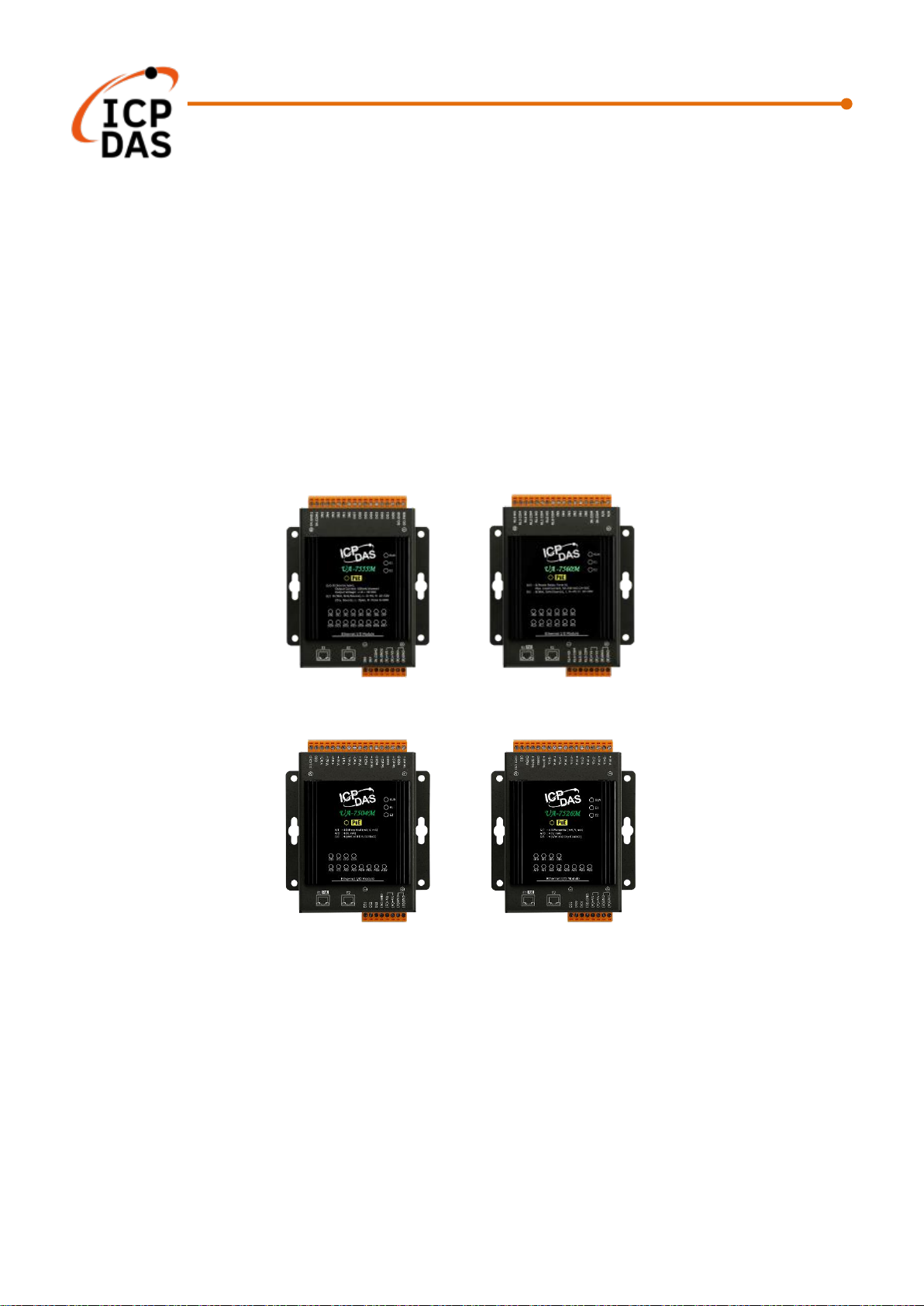
UA-7000 Series IIoT OPC UA I/O Module
UA-7555M
UA-7560M
UA-7504M
UA-7526M
Technical support: service@icpdas.com
Technical Editor: Tim Chen
Editor: Eva Li

OPC UA I/O Series User Manual V2.0 – ICP DAS
2
Warranty
All products manufactured by ICP DAS are under warranty regarding defective materials for a
period of one year, beginning from the date of delivery to the original purchaser.
Warning
ICP DAS assumes no liability for any damage resulting from the use of this product. ICP DAS
reserves the right to change this manual at any time without notice. The information
furnished by ICP DAS is believed to be accurate and reliable. However, no responsibility is
assumed by ICP DAS for its use, not for any infringements of patents or other rights of third
parties resulting from its use.
Copyright
Copyright @ 2020 by ICP DAS Co., Ltd. All rights are reserved.
Trademark
The names used for identification only may be registered trademarks of their respective
companies.
Contact US
If you have any problem, please feel free to contact us.
You can count on us for quick response.
Email: service@icpdas.com
For more product information please refer to website: www.icpdas.com

OPC UA I/O Series User Manual V2.0 – ICP DAS
3
Revision History
This chapter provides revision history information to this document.
The table below shows the revision history.
Revision
Date
Description
V1.0
06/2020
Initial issue
1. Release new DIO models: UA-7555M/UA-7560M
2. Provide OPC UA and MQTT communication functions
V2.0
09/2020
1. Release new AIO models: UA-7504M/UA-7526M
2. Provide new functions: Scaling

OPC UA I/O Series User Manual V2.0 – ICP DAS
4
Content of Table
Revision History ................................................................................................................ 3
Content of Table ................................................................................................................ 4
1. UA I/O Introduction: .................................................................................................... 7
1.1 Introduction ............................................................................................................ 7
1.2 Features ................................................................................................................ 8
1.3 Selection Guide ..................................................................................................... 9
1.4 Specifications....................................................................................................... 10
1.4.1 Software Specifications (Series Common) ............................................................ 10
1.4.2 UA-7555M Specifications ...................................................................................... 11
1.4.3 UA-7560M Specifications ...................................................................................... 12
1.4.4 UA-7504M Specifications ...................................................................................... 13
1.4.5 UA-7526M Specifications ...................................................................................... 14
1.5 Wire Connections / Pin Assignments ................................................................... 15
1.5.1 UA-7555M Wire Connections / Pin Assignments .................................................. 15
1.5.2 UA-7560M Wire Connections / Pin Assignments .................................................. 16
1.5.3 UA-7504M Wire Connections / Pin Assignments/Jumper Pic ................................ 17
1.5.4 UA-7526M Wire Connections/Pin Assignments/Jumper Pic .................................. 18
1.6 Dimensions .......................................................................................................... 19
1.6.1 UA-7555M/UA-7560M/UA-7504M/UA-7526M Dimensions ................................... 19
2. Quick Start: Hardware/Network Connection ...........................................................20
2.1. Hardware Connection .......................................................................................... 20
2.1.1. Preparations for Devices .................................................................................... 20
2.1.2. AI/AO Jumper Setting ........................................................................................ 20
2.1.3. Hardware Wiring ................................................................................................ 22
2.2. Network Connection ............................................................................................ 23
2.2.1. Connection by Factory Default Settings (For New UA) ....................................... 24
2.2.2. Connection by Utility Searching .......................................................................... 26
3. Main Function Settings .............................................................................................30
3.1 Settings for Using OPC UA Connection ................................................................. 31
3.1.1 OPC UA Server Connection Settings (UA I/O) ...................................................... 32
3.1.2 OPC UA Client Side: InduSoft Simple Application................................................. 33
3.1.3 Secure Encrypted Connection: OPC UA Certificate .............................................. 34
3.2 Settings for Using MQTT Connection .................................................................... 35
3.2.1 Connecting to MQTT Broker ................................................................................. 36
3.2.2 MQTT Client Setting of the UA I/O ........................................................................ 37

OPC UA I/O Series User Manual V2.0 – ICP DAS
5
3.2.3 Secure Encrypted Connection: MQTT Certificate ................................................. 42
4. Main Menu: Parameter Descriptions ........................................................................43
4.1 Main Menu - System Setting .................................................................................. 43
4.1.1 Overview .............................................................................................................. 43
4.1.2 Network Setting .................................................................................................... 44
Network Setting (LAN) .......................................................................... 44
Hostname Setting ................................................................................. 45
4.1.3 Time Setting ......................................................................................................... 46
Date and Time Display ......................................................................... 46
Set the time manually ........................................................................... 47
4.1.4 Account Setting .................................................................................................... 48
4.1.5 I/O Setting............................................................................................................. 49
Digital Input .......................................................................................... 49
Digital Output ........................................................................................ 50
Analog Input ......................................................................................... 51
Analog Output ...................................................................................... 52
4.1.6 I/O Status ............................................................................................................. 53
Digital Input .......................................................................................... 53
Digital Output ........................................................................................ 54
Analog Input ......................................................................................... 55
Analog Output ...................................................................................... 56
4.1.7 Firmware Setting................................................................................................... 57
Restore Factory Setting ........................................................................ 57
Update Firmware .................................................................................. 59
4.2 Main Menu - OPC UA Setting ................................................................................ 61
4.2.1 Server Setting ....................................................................................................... 62
4.2.2 Certificate ............................................................................................................. 63
4.3 Main Menu – MQTT Setting ................................................................................... 64
4.3.1 Connection Setting ............................................................................................... 64
4.2.2 Client Setting ........................................................................................................ 65
4.3.3 Certificate ............................................................................................................. 68
4.4 Main Menu – Advanced Setting ............................................................................. 70
4.4.1 Scaling .................................................................................................................. 70
5. Recovering Firmware Setting (Reset) ......................................................................71
Appendix A. Menu Path Diagram Description ...............................................................73

OPC UA I/O Series User Manual V2.0 – ICP DAS
6
Appendix B. MQTT JSON Format of the UA Series.......................................................74
Appendix C. How to Change OS Password? .................................................................75
OPC UA I/O Series User Manual V2.0 – ICP DAS
7
1. UA I/O Introduction:
UA I/O series is a series of OPC UA I/O modules, also known as UA-7000. The main model is UA-75xxM.
This series built-in provides the communication protocol functions of the Industrial Internet of Things
(IIoT), including OPC UA Server and MQTT Client functions. It allows user to choose the network
communication method according to the needs and environment, and directly transfer the value of the
I/O channel to the cloud IT system or the field-side control system to read and write the I/O data.
1.1 Introduction
OPC UA I/O modules is a series of Ethernet I/O modules that built-in with the OPC UA Server and MQTT
Client services. The OPC UA I/O module, also called UA I/O or UA-7000, supports the OPC UA server and
MQTT client function in industrial networking communication. Users can choose the networking mode
according to their needs and environment, to transmit the values of built-in I/O channels to the cloud IT
system or field control system for reading and writing. Support Scaling. Let the analog signal be
converted into a more readable value.
UA I/O Series provides a Web-based User Interface (Web UI) to configure the module, control the output
channels, monitor the connection, and I/O status via a normal web browser. It is easy, fast, and no extra
APP needed.

OPC UA I/O Series User Manual V2.0 – ICP DAS
8
1.2 Features
Built-in OPC UA Server Service
Compliance with IEC 62541 Standard. Provides functions of Active Transmission, Transmission
Security Encryption (SSL/TLS), User Authentication (X.509 Certificates / Account password),
Communication Error Detection and Recovery, etc. to connect SCADA or OPC UA Clients.
Recommend to keep the maximum number of sessions within 3 connections.
Built-in MQTT Client Service
Build-in MQTT Client Service (Compliance with MQTT V.3.1.1 protocol). Provides functions of IoT
Active M2M Transmission, QoS (Quality of Service), Retains Mechanism, Identity Authentication,
Encryption, Last Will, etc.
Support Scaling
AI/O modules support Scaling. Let the analog signal be converted into a more readable value.
Built-in Web Server to Provide the Web User Interface
UA I/O Series provides a Web-based User Interface (Web UI) to configure the module, control the
output channels, monitor the connection, and I/O status via a normal web browser. It is easy, fast,
and no extra APP needed.
Built-in I/O Channels
UA I/O series has built-in AI, AO, DI, or DO channels, which is convenient for users to choose
different models according to different needs.
2-port Ethernet Switch for Daisy-Chain Topology
The cabling of Daisy-Chain Topology is much easier and total costs of cable and switch are
significantly reduced.
IEEE 802.3af-compliant Power over Ethernet (PoE)
UA I/O follows IEEE 802.3af compliant Power over Ethernet (PoE) specification. It allows receiving
power from PoE enabled network by Ethernet pairs. This feature provides greater flexibility and
efficiency to simplify system design, save space, and reduce wirings and power sockets.

OPC UA I/O Series User Manual V2.0 – ICP DAS
9
1.3 Selection Guide
UA-7000 Series UA I/O Selection Guide:
UA-7000 Series OPC UA I/O Module Selection Guide
Module
AI
AO
DI
DO
Ch.
Type
Ch.
Type
Ch.
Type
Ch.
Type
UA-7555M - - - -
8
Dry (Source),
Wet
(Sink,Source)
8
Open Collector
(Sink)
UA-7560M - - - -
6
Wet
(Sink/Source)
6
Power Relay
Form A (SPST
N.O.)
UA-7504M
4
±500mV, ±1V, ±5V,
±10V, 0~20mA,
±20mA, 4~20mA
4
0~5V, ±5V, 0~10V,
±10V, 0~20mA,
4~20mA
4
Dry (Source),
Wet (Sink)
-
-
UA-7526M
6
±500 mV, ±1V, ±5V,
±10V, 0~20mA,
±20mA, 4~20mA
2
0~5V, ±5V, 0~10V,
±10V, 0~20mA,
4~20mA
2
Dry (Source),
Wet
(Sink,Source)
2
Open Collector
UA-7517M-10
10
/
20
±150mV, ±500mV,
±1V, ±5V, ±10V,
±20mA, 0~20mA,
4~20mA
- - - - -
-
UA-7519ZM
8
±150mV, ±500mV,
±1V, ±5V, ±10V,
±20mA, 0~20mA,
4~20mA
Thermocouple: J, K,
T, E, R, S, B, N, C, L,
M, LDIN43710
- - - - 3
Open Collector
(Sink)
OPC UA I/O Series User Manual V2.0 – ICP DAS
10
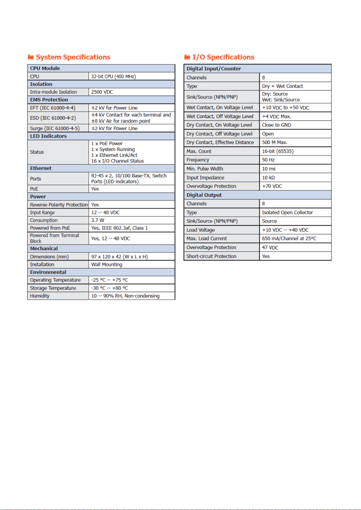
1.4 Specifications
1.4.1 Software Specifications (Series Common)
Protocol
OPC UA
Server
● OPC Unified Architecture: 1.02
● Core Server Facet
● Data Access Server Facet
● Method Server Facet
● UA-TCP UA-SC UA Binary
● User Authentication:
- Username/Password
- X.509 Certificate
● Security Policy:
- None
- Basic128Rsa15 (Sign, Sign & Encrypt)
- Basic256 (Sign, Sign & Encrypt)
● Recommend to keep the maximum number of sessions within 3 connections
MQTT Client
It can connect to the set MQTT Broker to read or control the I/O channel value
by the publish/subscribe messaging mechanism. (MQTT Ver. 3.1.1; TLS Ver. 1.2)
Function
Web
Interface for
Configuration
The system operation can be performed through the browser without installing
software tools.
Scaling
Convert the analog signal to a more readable value.
This function is only available for modules with AI/O.
OPC UA I/O Series User Manual V2.0 – ICP DAS
11
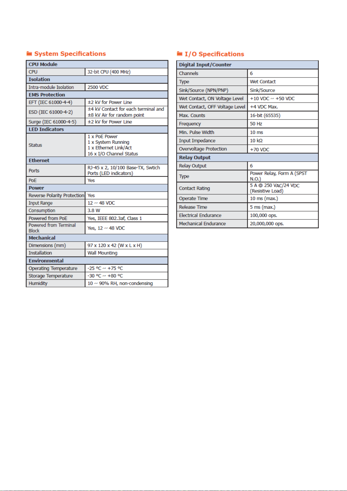
1.4.2 UA-7555M Specifications
OPC UA I/O Series User Manual V2.0 – ICP DAS
12
1.4.3 UA-7560M Specifications
OPC UA I/O Series User Manual V2.0 – ICP DAS
13
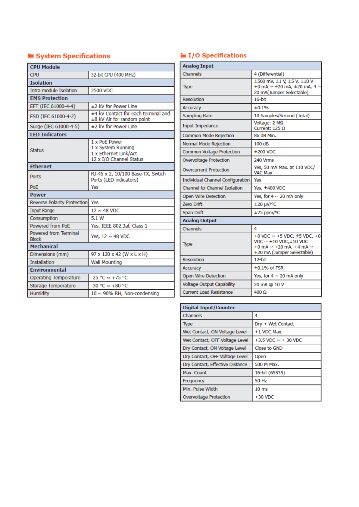
1.4.4 UA-7504M Specifications
OPC UA I/O Series User Manual V2.0 – ICP DAS
14
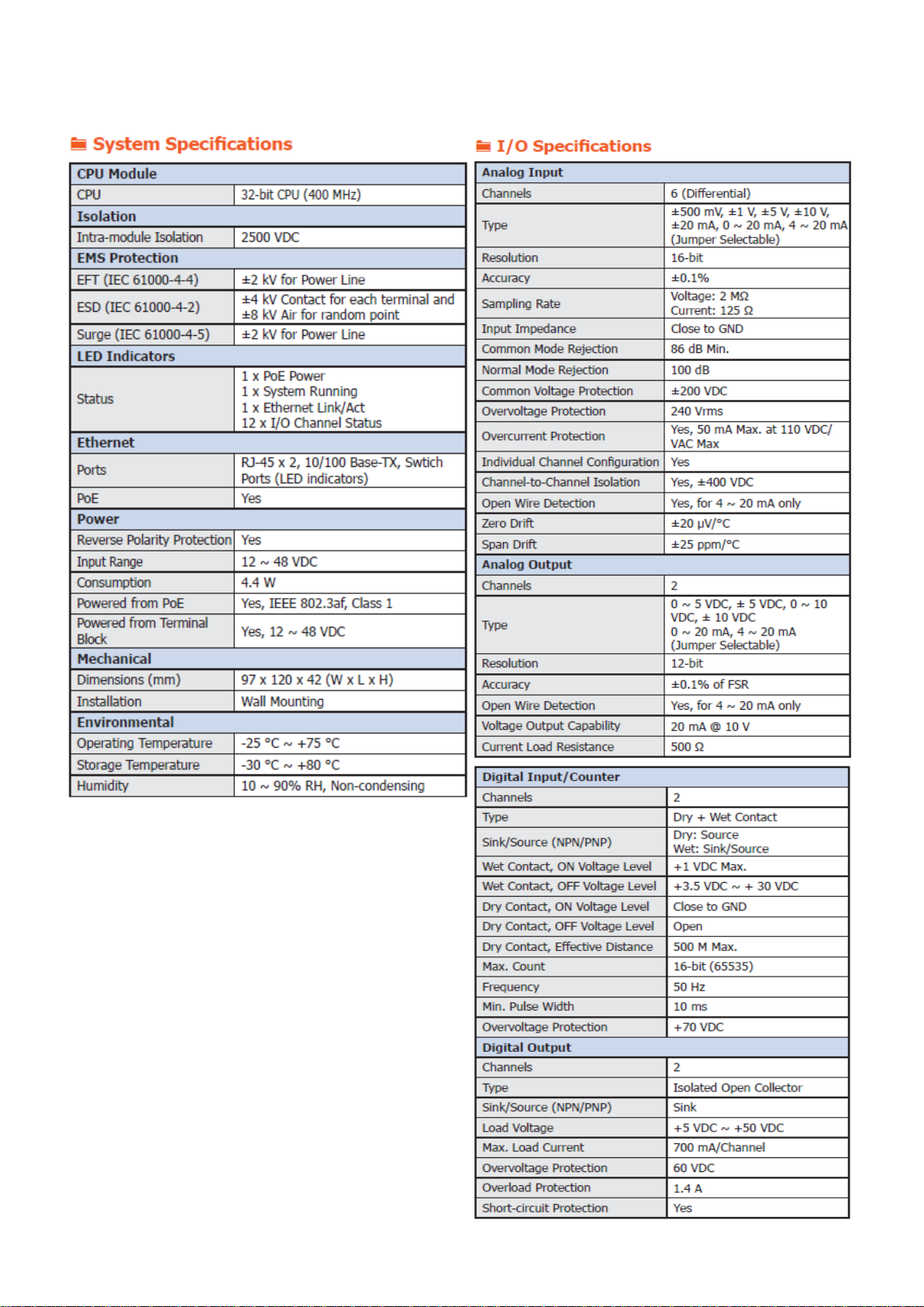
1.4.5 UA-7526M Specifications
OPC UA I/O Series User Manual V2.0 – ICP DAS
15
1.5 Wire Connections / Pin Assignments
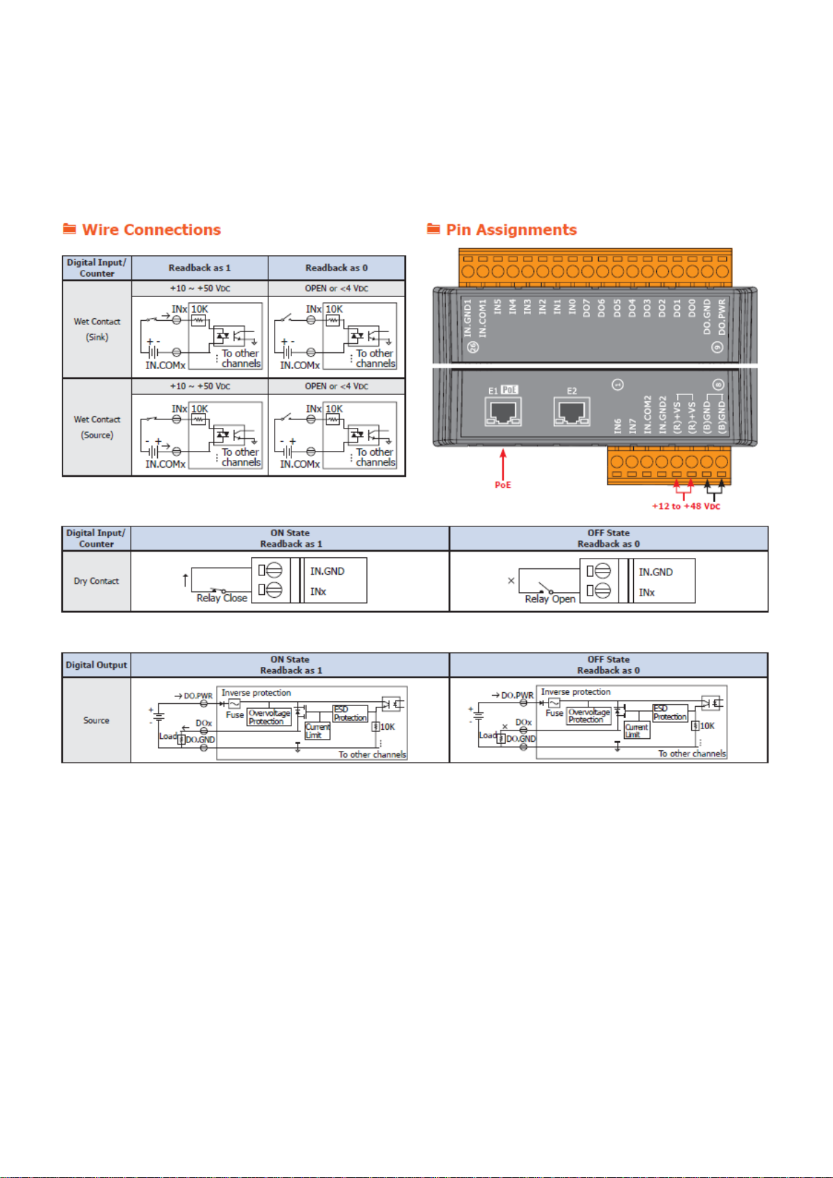
1.5.1 UA-7555M Wire Connections / Pin Assignments
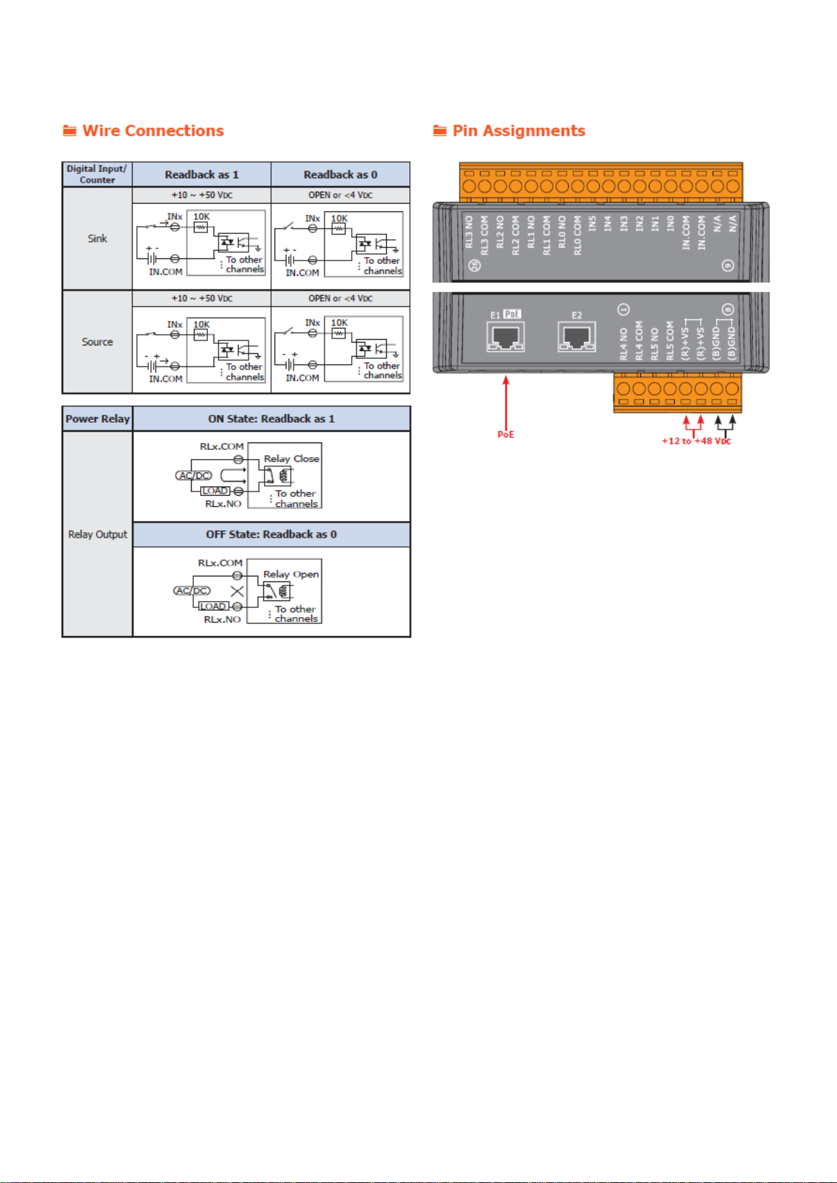
OPC UA I/O Series User Manual V2.0 – ICP DAS
16
1.5.2 UA-7560M Wire Connections / Pin Assignments
OPC UA I/O Series User Manual V2.0 – ICP DAS
17
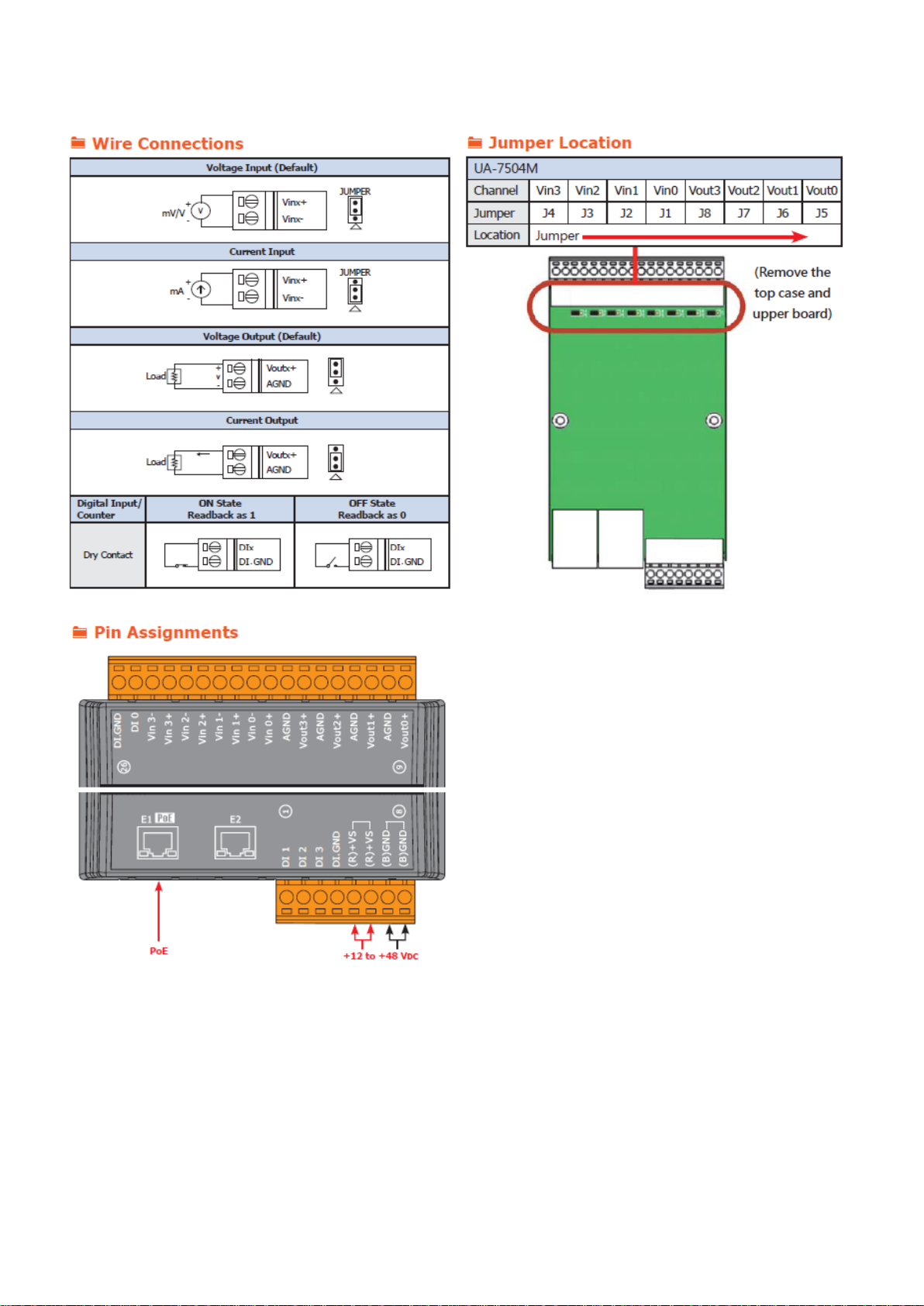
1.5.3 UA-7504M Wire Connections / Pin Assignments/Jumper Pic
OPC UA I/O Series User Manual V2.0 – ICP DAS
18
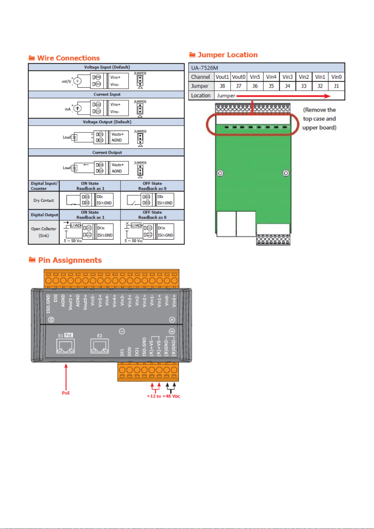
1.5.4 UA-7526M Wire Connections/Pin Assignments/Jumper Pic
OPC UA I/O Series User Manual V2.0 – ICP DAS
19
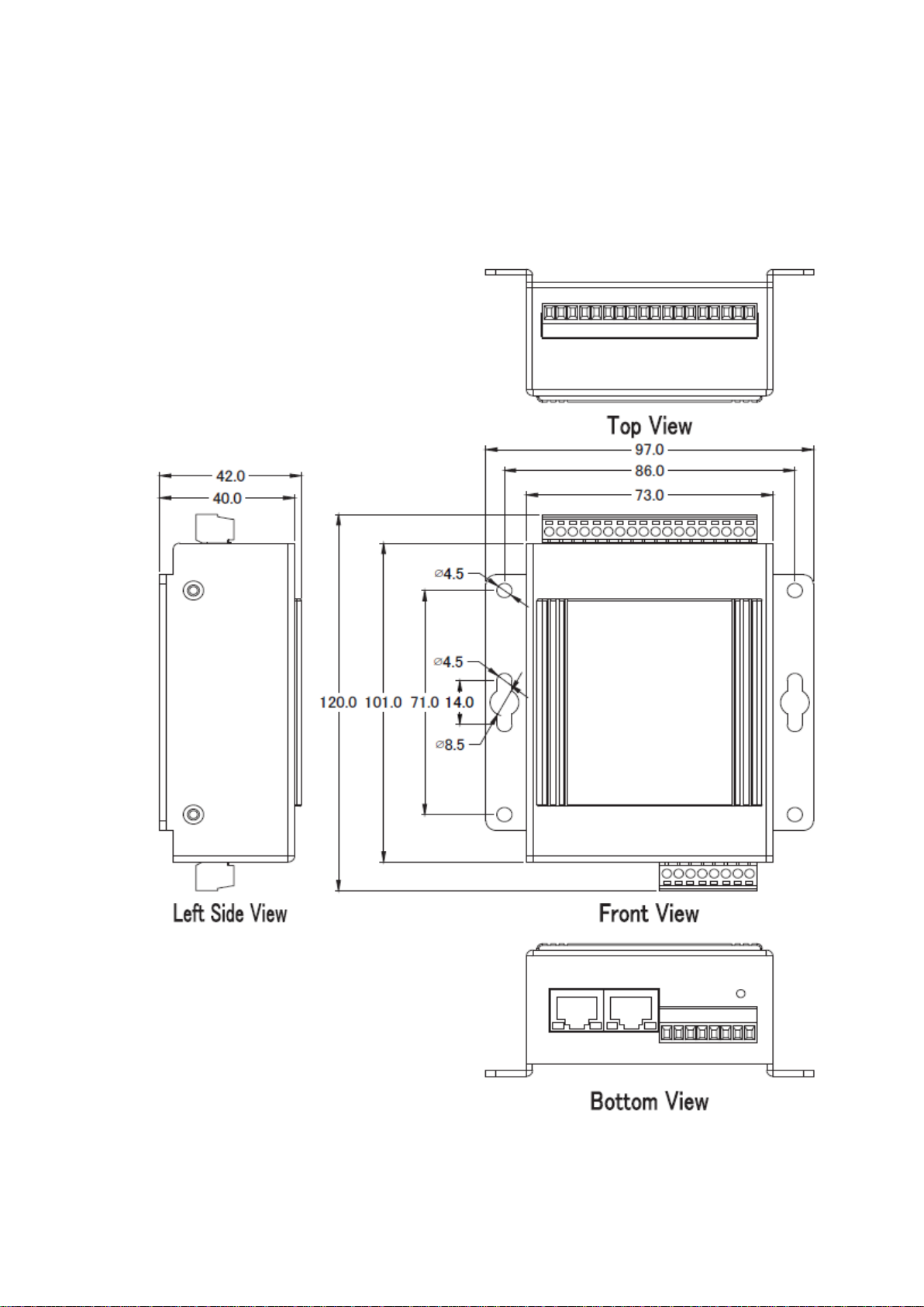
1.6 Dimensions
1.6.1 UA-7555M/UA-7560M/UA-7504M/UA-7526M Dimensions
(Unit: mm)
OPC UA I/O Series User Manual V2.0 – ICP DAS
20
2. Quick Start: Hardware/Network Connection
This chapter describes the UA I/O module’s hardware connection, network connection and quick setting.
For how to set up a project via the Web UI on the browser, please refer to Chapter 3.
2.1. Hardware Connection
This section describes the hardware wiring and connection for the UA I/O module.
2.1.1. Preparations for Devices
In addition to the UA I/O modules (Ex: UA-7555M), please prepare the following:
1. PC/NB: Can connect to the network and set the network
2. Ethernet Switch/Hub: e.g. NS-205 or PoE Switch NSM-208SE
3. Power Supply: +12 ~ +48 VDC, e.g. MDR-60-24 (If using PoE Switch, user can save a power supply.)
2.1.2. AI/AO Jumper Setting
This section is for setting the AI/AO jumpers, if use DI/O module, please go to the next section.
Setting the Selection Jumpers for Analog channels:
1. Remove the top case and upper board of the module if need to change the selection
jumper, the selection jumpers are next to the connector.
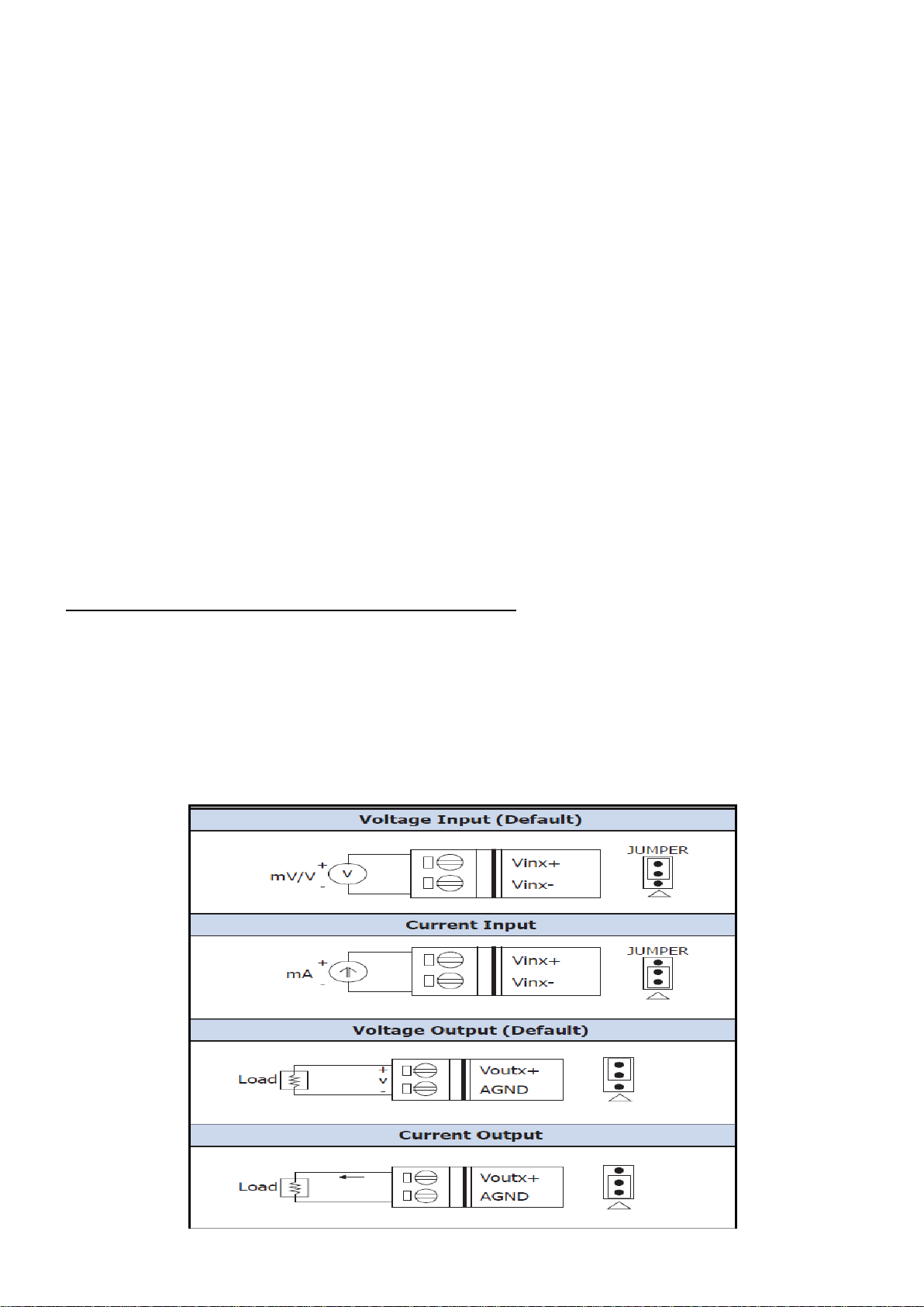
2. Set up the Jumper corresponding to the type of voltage/current and input/output for each
analog channel.
Voltage/Current Input/output Selection Jumper: (Default as AI/AO: Voltage/Voltage)
OPC UA I/O Series User Manual V2.0 – ICP DAS
21
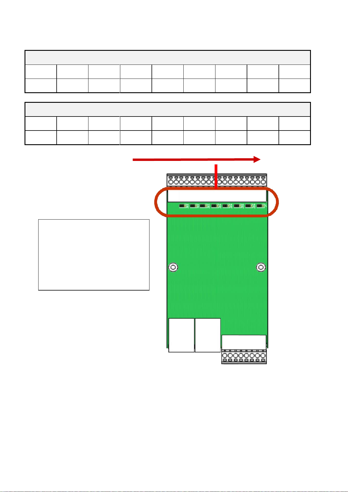
Jumper Location:
UA-7504M
Channel
Vin3
Vin2
Vin1
Vin0
Vout3
Vout2
Vout1
Vout0
Jumper
J4
J3
J2
J1
J8
J7
J6
J5
UA-7526M
Channel
Vout1
Vout0
Vin5
Vin4
Vin3
Vin2
Vin1
Vin0
Jumper
J8
J7
J6
J5
J4
J3
J2
J1
Jumper Direction
(
Jumpers default
as:
Input: Voltage
Output: Voltage.
If you need to change the
jumpers, remove the top case
and upper board first.)
OPC UA I/O Series User Manual V2.0 – ICP DAS
22
2.1.3. Hardware Wiring
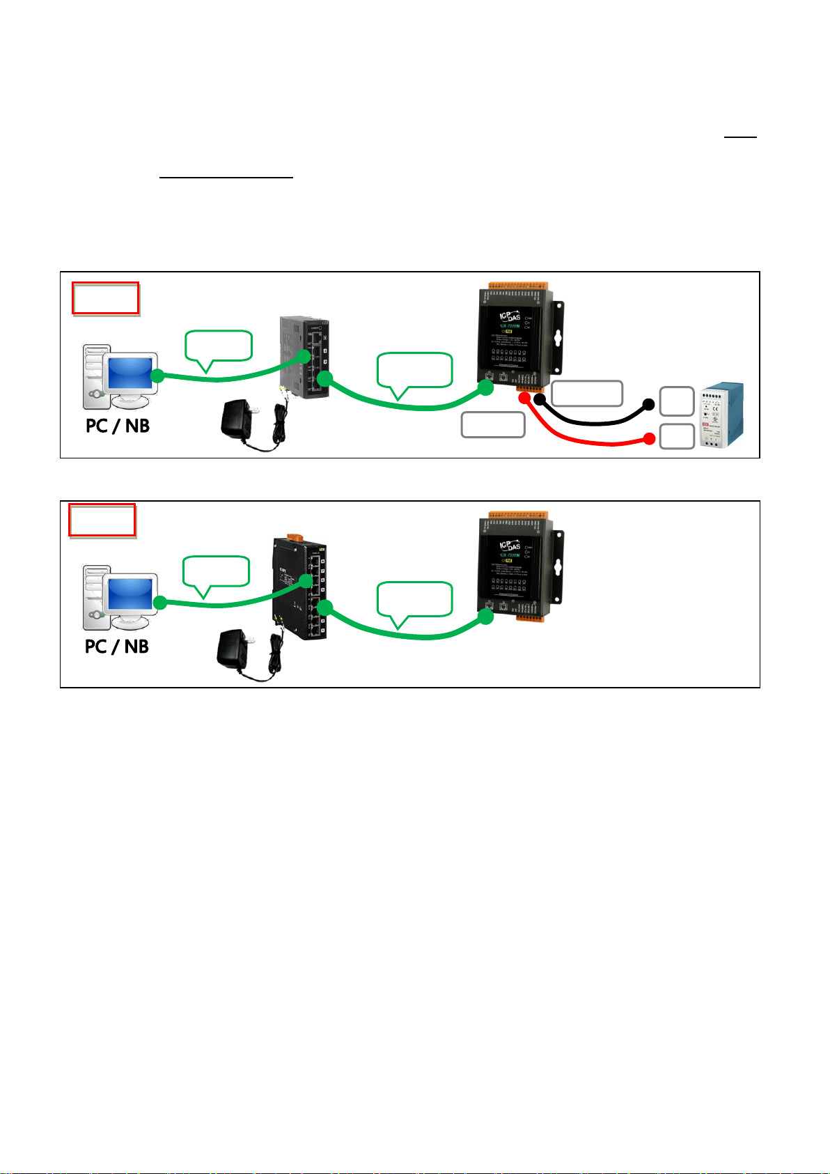
Connect the UA-7000 I/O Module with the RJ-45 Ethernet port to an Ethernet switch/hub and PC (Fig.1).
Beside, UA-7000 support PoE (Power over Ethernet). If using the PoE switch, do not need one more
power supply (Fig.2 for PoE Switch). You can also directly link the UA-7000 to PC with an Ethernet cable.
After power is connected, please【wait 1 minute】for UA-7000 start-up procedure. When the "RUN" light
starts flashing, it represents the boot is complete.
PoE Switch/Hub
UA-7000
UA I/O
Cable
Cable
Power Supply
Fig.2
Switch/Hub
UA-7000
UA I/O
(R)+VS
(B)GND
Cable
Cable
Power Supply
+V
Power Supply
12 ~ 48 VDC
-V
Fig.1
OPC UA I/O Series User Manual V2.0 – ICP DAS
23
2.2. Network Connection
This section introduces 3 methods to connect to the UA I/O Web UI (User Interface).
Setting new UA I/O module or the new user please uses the method A in the Chapter 2.2.1 (The same
method as the “UA I/O Quick Start” document.). Other users please see the following introductions to
choose method B or C.
The methods to login the UA I/O Web UI:
A. Using Factory Default Setting:
Suitable for setting a new UA I/O module and the PC network IP is not in the same domain with
UA I/O. This method changes the PC network IP to be the same domain with the network IP of the
UA I/O factory default values to login the Web UI. (Refer Section 2.2.1)
B. Using Software Utility:
Suitable for quick setting when many UA I/O are in the network but the IP are unknown. UA
products provide a free software utility for auto searching UA products in the network and can quick
jump to the login web page of UA. (Refer Section 2.2.2)
C. Using IP Address:
Suitable for the UA has a fixed IP and in the same domain with the PC. If the UA has a fixed IP and
in the same domain with the PC, users can directly enter the IP in the address bar of a web browser
and log in to the Web UI of the UA.
After login the UA I/O Web UI, then can set up the UA project.

OPC UA I/O Series User Manual V2.0 – ICP DAS
24
2.2.1. Connection by Factory Default Settings (For New UA)
The factory default settings of the UA I/O series are as the following table:
Factory Default Settings of UA I/O Modules
Network
IP
192.168.255.1
Assign UA I/O a new IP setting
according to your case.
Netmask
255.255.0.0
Gateway
192.168.1.1
OS
Account
Username
root
After login, change your
password as soon as
possible.
(Section 4.1.4 for Web UI)
(Appendix C for OS)
Password
icpdas
Web UI
Account
Username
root
Password
root
1. Change the PC’s IP setting as following. (Write down the PC original network settings
before modify.)
IP
192.168.255.10
Subnet mask
255.255.0.0
Gateway address
192.168.1.1
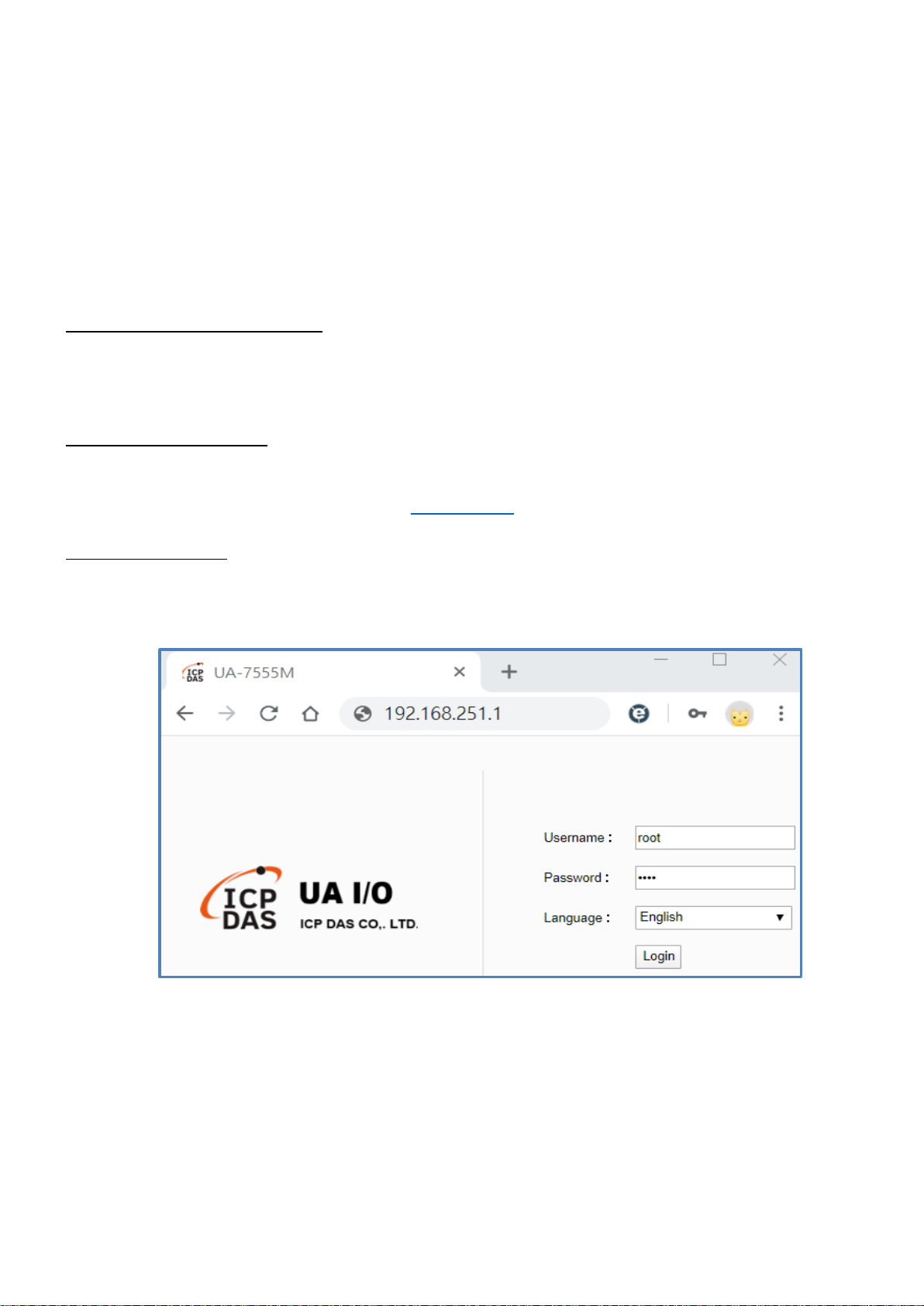
2. Make sure the PC and UA I/O is connecting through Ethernet. Then open a PC side browser
(Ex: Chrome, IE…).
3. Type http://192.168.255.1 in the URL address. Use Web UI default username / password
“root” / “root” to login the system.

OPC UA I/O Series User Manual V2.0 – ICP DAS
25
4. Click【System Setting】【Network Setting】【Network Setting(LAN1)】to change the IP setting
by user network.
5. Save the IP setting, restore the PC original IP settings, and type the new IP in the browser as step-2 to
login the Web UI of UA I/O. Then configure user’s UA project.

OPC UA I/O Series User Manual V2.0 – ICP DAS
26
2.2.2. Connection by Utility Searching
Setting new UA I/O or the new user please uses the method in the Chapter 2.2.1. (Method A)
If the UA I/O has a fixed IP and in the same domain as the PC, users can directly enter the IP in the
address bar of a web browser and log in to the Web UI of the UA. (Method C)
This section introduces the 2nd method(B) that users use the UA Utility to search the Network IP. This
method is suitable for connecting multiple UA series controllers or I/O modules to the Internet, but
the IP addresses of UA are unknown or need to modify the UA quickly.
UA Utility is a free tool software to quickly search each UA series on the network and connect to
its Web UI for setting UA series products and project.
In the PC, install the UA Utility (named “ua-series_utility.exe”), and then run it to connect the device.
Please download the utility program from the website:
https://www.icpdas.com/en/download/index.php?nation=US&kind1=6&kind2=17&model=&kw=ua-
1. Install and execute the Utility
Run the UA Utility (file name: UA-series_utility.exe) to install the Utility program.

OPC UA I/O Series User Manual V2.0 – ICP DAS
27
2. Create a new connection
Click “New” to add a connection item and give a name for it.
3. Search the UA controller
Mouse double-click on the name you created (or single-click and then click the “Connect”
button), this utility will scan and list all UA devices over the network.
1
2

OPC UA I/O Series User Manual V2.0 – ICP DAS
28
4. Connect to the UA Series
Click the device name you want to connect to, and then click the “Connect” button. It will
connect to the UA webpage via the default Web browser (IE/Chrome…).
5. Connection to the UA Web UI
The default web browser will be run and direct go to the UA login web site.
Please enter the username and password to login the UA series Web UI.
The factory default username: root. The factory default password: root.
1
2

OPC UA I/O Series User Manual V2.0 – ICP DAS
29
6. Login the Web UI of the UA Series
When login into the web interface, the UA default home page (the main configuration screen) will
as below, and will automatically read setting of that UA to the webpage.

OPC UA I/O Series User Manual V2.0 – ICP DAS
30
3. Main Function Settings
This chapter introduces some of the most important and commonly used functions of UA I/O and their
setting steps.
OPC UA I/O modules is a series of Ethernet I/O modules that built-in with the OPC UA Server and MQTT
Client services. The OPC UA I/O module, also called UA I/O or UA-7000, supports the OPC UA server and
MQTT client function in industrial networking communication. Users can choose the networking mode
according to their needs and environment, to transmit the values of built-in I/O channels to the cloud IT
system or field control system for reading and writing. So, the main functions are the OPC UA connection
and the MQTT connection. This chapter will introduce them first. Each function can be divided into the
settings for the Server/Broker and Client, and how to enable secure encrypted communication, and how
to download/upload the secure certificates. In addition, the AI/AO, DI/DO function applications are also
very important for the UA I/O, which will be added to this chapter soon.
OPC UA / MQTT Communication Advantages: (V.S. traditional Modbus Communication)

OPC UA I/O Series User Manual V2.0 – ICP DAS
31
3.1 Settings for Using OPC UA Connection
This section introduces how to set up the OPC UA communication service of UA I/O, and recommends
compatible ICP DAS products.
UA I/O module built-in OPC UA Server Service that compliance with IEC 62541 Standard. Provides
functions of Active Transmission, Transmission Security Encryption (SSL/TLS), User Authentication (X.509
Certificates / Account password), Communication Error Detection and Recovery, etc. to connect SCADA
or OPC UA Clients. Recommend to keep the maximum number of sessions within 3 connections.
OPC UA connection includes the following settings that will be introduced in 3 sub-sections.
1. OPC UA Server Connection Settings (UA I/O)
2. OPC UA Client I/O Settings (Recommend to use the InduSoft product of ICP DAS.)
3. How to enable secure encrypted function, and download/upload the encrypted certificates
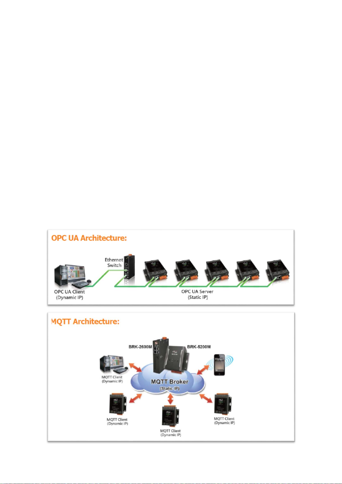
OPC UA Architecture and Advantages of the UA I/O:

OPC UA I/O Series User Manual V2.0 – ICP DAS
32
3.1.1 OPC UA Server Connection Settings (UA I/O)
UA I/O module built-in OPC UA Server function and itself is the Server side of the connection. So, when
setting up the Server, you only need to set the connection port number and choose the login method
(via anonymous, username, or certificate). Usually, the user will enable the username login method, so
the user can set the username/password of the account besides.
1. Connection Setting
Click Main Menu【OPC UA Setting】【Server Setting】【Connection Setting】.
2. When enabling username password login, please set the account in the following menu path.
Menu Path:【System Setting】【Account Setting】 (Appendix A).
If users enable the secure and encrypted OPC UA Certificate Login, need to upload/download
certificates, please refer to Sec.3.1.3 .
After completing the Server connection settings, then set the Client connection (refer to Sec.3.1.2), and
then can communicate with each other.
1. Enter the port number
2. Enable the login method.
For better security, please enable
Username Password Login or
Certificate Login (refer to 3.1.3).
3. Click Save after the above settings.
3. Click Save after the settings.
1. Set up username
2. Set up Password
and retype Password

OPC UA I/O Series User Manual V2.0 – ICP DAS
33
3.1.2 OPC UA Client Side: InduSoft Simple Application
After setting the OPC UA Server-side (UA I/O), you only need to configure the OPC UA Client for
connection. Now, go to the Client device that connects with UA I/O, and set the corresponding data
point. We recommend using ICP DAS InduSoft products as the Client device. It is easier to set up
relatively and can connect to UA I/O faster. For detailed settings, please refer to the InduSoft manual.
The setting screen is as follows:

OPC UA I/O Series User Manual V2.0 – ICP DAS
34
3.1.3 Secure Encrypted Connection: OPC UA Certificate
When using the OPC UA connection, in addition to the account login for security, users can also enable
the certificate login to double the protection by the secure encryption. This section describes how to
download/upload the certificates. If you do not want to enable the certificate login, please skip.
When enabling the OPC UA certificate login, the Server/Client both sides of the connection need to add
certificates to each other's trust zones. This section will show how to do the steps.
Menu Path:【OPC UA Setting】【Certificate】。 (Appendix A).
A. Provide the OPC UA Server Certificate of the UA I/O to the Client device. That is, download the
Server certificate file of the UA I/O, and then upload and import it into the software (or APP) of the
OPC UA Client device.
Click the "Download" button to get the
Certificate file generated by the Server.
File Name: icpdasuaserver.der
B. Get the Trusted Certificate file of the connected OPC UA Client, save it in the PC, and upload it into
the UA I/O module.
1) Click the “Upload” button to open
the “open” window.
2) Select the Trusted Certificate file.
Import this file into OPC UA Client APP.

OPC UA I/O Series User Manual V2.0 – ICP DAS
35
3.2 Settings for Using MQTT Connection
This section introduces how to set up the MQTT Client communication of UA I/O, and recommends the
compatible ICP DAS products.
UA I/O module built-in MQTT Client Service (Compliance with MQTT V.3.1.1 protocol). Provides
functions of IoT Active M2M Transmission, QoS (Quality of Service), Retains Mechanism, Identity
Authentication, Encryption, Last Will, etc.
MQTT connection includes the following settings that will be introduced in 3 sub-sections.
1. MQTT Broker Connection Settings (Recommend the UA-2xxx/52xx & BRK series of ICP DAS)
2. MQTT Client side I/O Settings (UA I/O)
3. How to enable secure encrypted function, and download/upload the encrypted certificates
MQTT Architecture and Advantages of the UA I/O:

OPC UA I/O Series User Manual V2.0 – ICP DAS
36
3.2.1 Connecting to MQTT Broker
UA I/O module built-in MQTT Client function and itself is the Client side of the connection. So, when
setting up the MQTT Broker, it is to set the data of the remote device (Broker) that the UA I/O module
wants to connect. The data includes Broker's IP address, port number, anonymous login, account
password login, etc.
MQTT Broker Device: recommend to use ICP DAS IIoT communication server UA-2200/5200/2600 series
or MQTT Broker BRK-2600M/5200M series.
Main Menu:【MQTT Setting】【Connection Setting】 (Appendix A).
If users enable the secure and encrypted MQTT Certificate Login, need to upload/download certificates,
please refer to Sec.3.2.3.
After completing the MQTT Broker connection settings, then set the Client connection (refer to
Sec.3.2.2), and then can communicate with each other.
1. IP address of the remote MQTT Broker
that wants to connect.
(MQTT Broker: refer UA-2200/5200 & BRK
series of ICP DAS)
2. Port number of the remote MQTT
Broker
3. Login username and password of the
remote MQTT Broker.
4. Click to save the settings.

OPC UA I/O Series User Manual V2.0 – ICP DAS
37
3.2.2 MQTT Client Setting of the UA I/O
UA I/O built-in MQTT Client function and itself is the MQTT Client side of the connect. When setting,
please set the connecting remote MQTT Broker device first, and then set the UA I/O module of the
MQTT client.
Reference for MQTT related basic knowledge:
MQTT (MQ Telemetry Transport) is a lightweight publish/subscribe messaging protocol. An MQTT-based
application will include two or more clients, which are applications exchanging messages, and a broker,
which is a server that accepts incoming messages and routes them to the appropriate destination client.
As with most publish-subscribe systems, message sends involve publishing on a specified topic. The
broker then forwards the message to all subscribers of that topic. These primitives can be used to build
different interaction patterns. (as the picture below)
MQTT gives you flexibility by specifying a Quality of Service (QoS) with each message. QoS is a
parameter available on each publish call. It is one of three levels:
QoS 0: At most once
QoS 1: At least once
Q0S 2: Exactly once
Provides a Quality-of-Service data delivery: QoS can be selected based on the needs of the
application.
MQTT Retained messages: The last published message (with retained flag set to true) is stored at the
broker so that new subscribers can immediately obtain last known good value rather than wait for the
next update from publisher.
REFERENCES: (The above information is from the following websites.)
https://micropython-iot-hackathon.readthedocs.io/en/latest/mqtt.html
https://devopedia.org/mqtt

OPC UA I/O Series User Manual V2.0 – ICP DAS
38
MQTT Client Setting of the UA I/O:
Manu Path:【MQTT Setting】【Client Setting】 (Appendix A).
Enable of JSON Format: Descriptions for the Enable (check “Enable”) / Disable (uncheck “Enable”)
Enable: Enter the Group setting screen, the Publish & Subscribe message is sent in a group.
Group setting (JSON Format) the Publish & Subscribe: Suitable for obtaining all I/O values at
one time, it can reduce network resources. It will pack all I/O point values into a JSON string,
and then send the JSON string as a message or subscribe JSON string to get all I/O values
back at one time. (Refer to Appendix B for the detailed JSON format)
Disable: Enter the Singly setting screen, the Publish & Subscribe message is sent in singly (P to P).
Singly setting (Point-to-point) the Publish & Subscribe: Suitable for I/O points that require
high real-time performance, or devices that do not support generating or parsing JSON
format.
Enable (Check)
Disable (Uncheck)
1. Set an update frequency for the task data.
Default: 1000 (Unit: ms)
2. Give a dead bend value for updating a float signal.
3. Enter a title of the disconnect notice.
4. Enter a disconnect notice.
5. Check “Enable”, the message is sent in groups.
Uncheck “Enable”, the message is sent in singly.

OPC UA I/O Series User Manual V2.0 – ICP DAS
39
The setting parameters for Both enable or disable the JSON Format:
MQTT Setting > Client Setting - Publish & Subscribe
Publish Topic
The topic of sending data / publishing message.
Publish QoS
The publish Qos (Quality of Service) levels. Default: 2
0: Delivering a message at most once.
1: Delivering a message at least once.
2: Delivering a message at exactly once.
Subscribe Topic
The topic of receiving data / subscribing message. It can copy the Publish
Topic of linked device.
Subscribe QoS
The subscribe Qos (Quality of Service) levels. Default: 2
0: Delivering a message at most once.
1: Delivering a message at least once.
2: Delivering a message at exactly once.
Retain
Set up if the Broker retains the message.
Save
Click to save the setting of this page.
When Enable JSON
format, it will pack
all I/O point values
into a JSON string,
and then send the
JSON string as a
message or
subscribe JSON
string to get all I/O
values back at one
time. (Refer to
When Disable JSON
format, it will
publish or subscribe
the message in
singly (Point-topoint). User needs to
set each I/O point.
5. If Broker retains the message
1. Topic for sending JSON string
2. QoS for sending JSON string
3. Topic for reading JSON string
4. QoS for reading JSON string
1. Topic for sending DO0 value
3. Topic for reading DO0 value

OPC UA I/O Series User Manual V2.0 – ICP DAS
40
Group Setting example: Check “Enable” of “JSON Format”
Here is an example of the lighting control in a factory. Use the I/O points of the UA-7555M module to
connect the light switches of Room 1 to 7 in the factory Building-A to monitor/control the on/off of the
room lights. We want to use the Group Setting, so check "Enable" of the "JSON Format". The following
is a parameter example for the settings of [MQTT Setting] > [Client Setting].
The Pub & Sub setting page when enable the JSON Format: Sending/Reading the JSON string
Note:
When setting the Pub/Sub of MQTT Client,
please also set the Alias of I/O channel,
which includes MQTT Alias and OPC UA
Description.
MQTT Client setting should cooperate
with MQTT Alias of the I/O channels
for the accuracy/readability of
MQTT communication settings.
Menu: 【System Setting】>【I/O Setting】
As shown on the right.
1. Set the update frequency for the task data (1000 ms)
2. Do not set the Dead Band, so keep 0.
3. Set disconnect Topic for 1F of Building-A (UA-7555M)
4. Set Will message: Disconnection
5. Check to Enable JSON format to enter the Pub/Sub
screen page for Group setting.
5. Check to set the Broker retain the message
1. Topic of the publish JSON string:
/Build-A/1F/UA-7555M/all I/O sending data
3. Topic of the subscribe JSON string:
/Build-A/1F/UA-7555M/all I/O reading data
4. Set QoS to level 2 for subscribe. 2: exactly once
2. Set QoS to level 2 for publish. 2: exactly once
6. Save all settings of this page.

OPC UA I/O Series User Manual V2.0 – ICP DAS
41
Singly Setting example: Uncheck “Enable” of “JSON Format”
Here is an example of the lighting control in a factory. Use the I/O points of the UA-7555M module to
connect the light switches of Room 1 to 7 in the factory Building-A to monitor/control the on/off of the
room lights. We want to use the Point-to-Point Setting, so uncheck "Enable" of the "JSON Format". The
following is a parameter example for the settings of [MQTT Setting] > [Client Setting].
Uncheck the JSON Format to do
the Point-to-Point singly setting (as
the left figure): User needs to set
up each Topic/QoS of Publish/
Subscribe for each I/O channel.
1. Set the Publish Topic of DO0
and set each IO#.
Topic means:
/Building-A/1F/light# of
UA-7555M/Topic
2. The level of sending Topic
for each IO#.
level 2: Exactly once
3. Set the Subscribe Topic of
DO0 and set each IO#.
Topic means:
/Building-A/1F/light# of
UA-7555M/Topic
4. The level of reading Topic
for each IO#.
level 2: Exactly once
5. Check to set the Broker
retain the message
6. Save all settings.
IO#
Ch.
2 1 3 4 5
1. Set the update frequency for the task data (1000 ms)
2. Do not set the Dead Band, so keep 0.
3. Set disconnect Topic for 1F of Building-A (UA-7555M)
4. Set Will message: Disconnection
5. Uncheck to Enable JSON format to enter the Pub/Sub
screen page for Group setting.

OPC UA I/O Series User Manual V2.0 – ICP DAS
42
3.2.3 Secure Encrypted Connection: MQTT Certificate
When using the MQTT connection, in addition to the account login for security, users can also enable the
SSL/TLS login to use the MQTT Certificate protection of the secure encryption. This section describes
how to download/upload the certificates. If you do not want to enable the certificate login, please skip.
The settings of MQTT certificate connection need to enable the SSL/TLS secure encryption. And the UA
I/O needs to get the certificate of the connecting device first. And then upload the certificates to UA I/O.
There are three types of certificates: Trusted Certificate, Certificate, and Private Key.
Please upload the files to the UA I/O module according to the type of certificates:
To perform the One-way authentication, you need to upload the Trusted Certificate.
To perform the Two-way authentication, you need to upload the Trusted Certificate first, and then
upload the Certificate and Private Key.
Note:
1. One-way authentication: The Client verifies the validity of Broker credentials; need to upload
the Trusted Certificate.
2. Two-way authentication: The Client and Broker verify the validity of the certificate with each
other; need to upload the Trusted Certificate first, and then upload the Certificate and Private
Key.
3. Trusted Certificate: File format must be PEM. Extension name must be “pem”, “cer”, or “crt”.
4. Certificate: File format must be PEM. Extension name must be “pem”, “cer”, or “crt”.
5. Private Key: File format must be PEM. Extension name must be “key”.
Manu Path:【MQTT Setting】【Client Setting】 (Appendix A).
1. Check “Enable”.
2. Click “Save” to show more items.
3. Select One-way
or Two-way.
4. Upload the certificates according to
the type.

OPC UA I/O Series User Manual V2.0 – ICP DAS
43
4. Main Menu: Parameter Descriptions
This chapter introduces the menu functions of the UA I/O web UI and more focused on the function
parameters of the menu. Each section introduces one main menu and its sub-menu functions. The
function location is showing in a brief text and diagram of【Menu Path】, for Menu Path introductions
please refer to Appendix A.
4.1 Main Menu - System Setting
System Setting is the first item of the Main Menu. This item is about the settings related to the hardware
and operating system.
4.1.1 Overview
Function: Display the current information of the hardware and operating system.
Support Module: All UA I/O modules support this function.
Manu Path:【System Setting】【Overview】 (Refer to Appendix A).
System Setting > Overview
Firmware Version
Display the firmware version of the UA I/O module.
Factory Version
Display the factory version (OS & UI) of the UA I/O module.
CPU
Display the current CPU usage of the module. Do not use to achieve 95%
or more.
Memory
Display the current memory usage of the module. Do not use to achieve
95% or more.
Disk
Display the current disk usage of the module. Do not use to achieve 95%
or more.

OPC UA I/O Series User Manual V2.0 – ICP DAS
44
4.1.2 Network Setting
Function: Display and set up the network settings of the UA I/O.
Support Module: All UA I/O modules support this function.
Manu Path:【System Setting】【Network Setting】 (Appendix A).
Network Setting (LAN)
System Setting > Network Setting - Network Setting (LAN)
Connection Mode
Specify an IP address: Users input the values in the fields of IP, Mask and
Gateway according to customer's network. Detail information for the
factory default value of UA controller network refers to the. Sec. 4.1.7
Obtain an IP address automatically (DHCP): It’s the Dynamic Host
Configuration Protocol mode. The system assigns the IP, Mask and
Gateway automatically.
IP Address
The LAN IP address of this UA I/O.
Factory Default: 192.168.255.1
Mask
The LAN mask address of this UA I/O.
Factory Default: 255.255.0.0
Gateway
The LAN gateway address of this UA I/O.
Factory Default: 192.168.1.1
MAC Address
The LAN MAC address of this UA I/O.
Save
Click to save the settings of LAN item.

OPC UA I/O Series User Manual V2.0 – ICP DAS
45
Hostname Setting
System Setting > Network Setting - Hostname Setting
Hostname
The host name of this UA I/O. Default: system value. User can give a new
name, but cannot be null, Chinese characters, or special symbols.
Save
Click to save the settings of this item.

OPC UA I/O Series User Manual V2.0 – ICP DAS
46
4.1.3 Time Setting
Function: Display and set up the date and time of the UA I/O.
Support Module: All UA I/O modules support this function.
Manu Path:【System Setting】【Time Setting】 (Appendix A).
Date and Time Display
System Setting > Time Setting - Date And Time Display
Date
Display the date of the UA I/O module, including year, month and day.
Time
Display the current time of the UA I/O module, including hour, minute and
second.
When the device time is one day different from the local computer time, a warning message "Please
check the time" will be displayed, as shown in the below.

OPC UA I/O Series User Manual V2.0 – ICP DAS
47
Set the time manually
System Setting > Time Setting - Set The Time Manually
Date
Set the system date of the UA I/O by manually. Directly enter the new
year/month/day, and then click “Save”.
Time
Set the system time of the UA I/O by manually. Directly enter the new
hour : minute : second, and then click “Save”.
Read The Local
Computer Time
Click [Read] can copy the current time of the using computer to the “Time
Setting” of this item.
Save
Click to save the settings of this item and update the data of “Time Setting”
to the “Date And Time Display” on the top of this page.

OPC UA I/O Series User Manual V2.0 – ICP DAS
48
4.1.4 Account Setting
Function: Display and set up the login username and password of the UA I/O Web UI.
Support Module: All UA I/O modules support this function.
Manu Path:【System Setting】【Account Setting】 (Appendix A).
System Setting > Account Setting
Username
The login username for the UA Web UI. Factory default: root. Cannot be null.
Password
The login password for the UA Web UI. Factory default: root. Cannot be null.
Confirm
Password
Retype the password for the operation conform when setting the new account
information.
Save
Click to save the settings of this page.

OPC UA I/O Series User Manual V2.0 – ICP DAS
49
4.1.5 I/O Setting
Function: Display and change the I/O settings of the UA I/O module.
Support Module: All UA I/O modules support this function.
Manu Path:【System Setting】【I/O Setting】 (Appendix A).
Digital Input
System Setting > I/O Setting - Digital Input
Channel
The channel name (number) of the UA I/O hardware.
MQTT Alias
The variable alias of the sending message (MQTT JSON format), when
using MQTT connection.
OPC UA Description
The messages got from the description column of OPC Client, when
using OPC UA connection.

OPC UA I/O Series User Manual V2.0 – ICP DAS
50
Digital Output
System Setting > I/O Setting - Digital Output
Channel
The channel name (number) of the UA I/O hardware.
MQTT Alias
The variable alias of the sending message (MQTT JSON format), when
using MQTT connection.
OPC UA Description
The messages got from the description column of OPC Client, when
using OPC UA connection.
Power-on Value
The initial value of the I/O channel after the power off and restart to on.

OPC UA I/O Series User Manual V2.0 – ICP DAS
51
Analog Input
System Setting > I/O Setting – Analog Input
Channel
The channel name (number) of the UA I/O hardware.
MQTT Alias
The variable alias of the sending message (MQTT JSON format), when
using MQTT connection.
OPC UA Description
The messages got from the description column of OPC Client, when
using OPC UA connection.
Input Type
Select the Input type by user’s need.

OPC UA I/O Series User Manual V2.0 – ICP DAS
52
Analog Output
System Setting > I/O Setting – Analog Output
Channel
The channel name (number) of the UA I/O hardware.
MQTT Alias
The variable alias of the sending message (MQTT JSON format), when
using MQTT connection.
OPC UA Description
The messages got from the description column of OPC Client, when
using OPC UA connection.
Power-on Value
The initial value of the I/O channel after the power off and restart to on.
(UA-7504M will support later, other models support now.)
Output Type
Select the Output type by user’s need.

OPC UA I/O Series User Manual V2.0 – ICP DAS
53
4.1.6 I/O Status
Function: Display and change the I/O status of the UA I/O module.
Support Module: All UA I/O modules support this function.
Manu Path:【System Setting】【I/O Status】 (Appendix A).
Digital Input
System Setting > I/O Status - Digital Input
Channel
The channel name (number) of the UA I/O hardware.
Value
Current channel status value. When the value changes, the signal LED
will change.
Status
GOOD, BAD, or UNCERTAIN.

OPC UA I/O Series User Manual V2.0 – ICP DAS
54
Digital Output
System Setting > I/O Status - Digital Output
Channel
The channel name (number) of the UA I/O hardware.
Value
Current channel status value. When the value changes, the signal LED
will change.
Status
GOOD, BAD, or UNCERTAIN.

OPC UA I/O Series User Manual V2.0 – ICP DAS
55
Analog Input
System Setting > I/O Status – Analog Input
Channel
The channel name (number) of the UA I/O hardware.
Value
Current channel status value.
When the input type is 4-20mA, if an abnormal state occurs, the value
will display as -32.768.
Status
GOOD, BAD, or UNCERTAIN.

OPC UA I/O Series User Manual V2.0 – ICP DAS
56
Analog Output
System Setting > I/O Status - Analog Output
Channel
The channel name (number) of the UA I/O hardware.
Value
Current channel status value.
Status
GOOD, BAD, or UNCERTAIN.

OPC UA I/O Series User Manual V2.0 – ICP DAS
57
4.1.7 Firmware Setting
Function: Provide firmware settings, such as restore factory setting and update firmware.
Support Module: All UA I/O modules support this function.
Manu Path:【System Setting】【Firmware Setting】 (Appendix A).
Restore Factory Setting
1. Check the “Enable” box to enable the “Restore” button, and then click on the “Restore” button to
start the restore operation.
2. A message will prompt appear, showing the installation process of the restore program, please wait
approximately 50 seconds.
1
2

OPC UA I/O Series User Manual V2.0 – ICP DAS
58
3. After the process finished, it appears a box message "During device restart, after waiting for 60
seconds, press OK", indicating that this restoration succeeds. If the box does not pop up, this
restoration fails.
4. After restarting, the module will restore the factory default settings as follows: (Web IP address
automatically changes to 192.168.255.1)
Factory Default Settings of UA I/O Modules
Network
IP (LAN)
192.168.255.1
Assign UA I/O a new IP setting
according to your case.
Netmask
255.255.0.0
Gateway
192.168.1.1
OS
Account
Username
root
After login, change your
password as soon as
possible.
(Section 4.1.4 for Web UI)
(Appendix C for OS)
Password
icpdas
Web UI
Account
Username
root
Password
root

OPC UA I/O Series User Manual V2.0 – ICP DAS
59
Update Firmware
When UA I/O has new functions, users can go to the UA series download center on the ICP DAS website
to download the latest version of Firmware software, and then update the firmware of your UA I/O
module according to the steps in this section.
UA series download center on the ICP DAS website:
https://www.icpdas.com/en/download/index.php?nation=US&kind1=&model=&kw=ua-
1. Click on the “Upload” button
2. Select the firmware file
3. Begin to upload the Firmware file, and the lower message box will show the progress.
1 1 2

OPC UA I/O Series User Manual V2.0 – ICP DAS
60
4. After upload the file, it begins to install the firmware.
5. After the process finished, it appears a box message "During device restart, after waiting for 60
seconds, press OK", indicating that this update succeeds. If the box does not pop up, this update
fails.
6. After restarting, the module will recover the UA I/O settings as follows:
Update Firmware of UA I/O Modules
Network
IP (LAN)
Keep the original setting
Assign UA I/O a new IP
setting according to your
case.
Netmask
Keep the original setting
Gateway
Keep the original setting
OS
Account
Username
root
After login, change your
password as soon as
possible.
(Section 4.1.4 for Web UI)
(Appendix C for OS)
Password
icpdas
Web UI
Account
Username
root
Password
root

OPC UA I/O Series User Manual V2.0 – ICP DAS
61
4.2 Main Menu - OPC UA Setting
This main menu aggregates all OPC UA related settings. This chapter focuses on parameter descriptions.
About the detailed steps and notices for using OPC UA connection/certificate, please refer to 3.1
Settings for Using OPC UA Connection of Chapter 3 Main Function Settings.
NOTE:
When the main menu “OPC UA Setting” has a message of “Please remove the server certificate” (as the
picture below), that means there is something error about the server certificate file.
Please click the menu【OPC UA Setting】【Certificate】 (Appendix A)
to remove the Server Certificate, the function of OPC UA menu will be normal again.
The operation to remove the Server Certificate, please refer to the next two section “4.2.2 Certificate“.

OPC UA I/O Series User Manual V2.0 – ICP DAS
62
4.2.1 Server Setting
Function: Provide the Server settings for using OPC UA connection.
Support Module: All UA I/O modules support this function.
Manu Path:【OPC UA Setting】【Server Setting】 (Appendix A).
OPC UA Setting > Server Setting - Connection Setting
Port
The communication port number of the OPC UA Server.
System Default: 48010.
Anonymous Login
Check to enable the anonymous login from clients.
Username
Password Login
Check to enable the user password login from clients.
(The username and password here is the same as the login username
and password of the Web UI.)
Certificate Login
Check to enable the certificate login from clients.
(refer to next section 4.2.2)
Save
Click to save the connection settings of OPC UA Server.

OPC UA I/O Series User Manual V2.0 – ICP DAS
63
4.2.2 Certificate
Function: When selecting OPC UA certificate connection, the UA I/O (Server side) needs to exchange the
certificate with the connecting client side. This page is about setting the OPC UA Certificate for
the security and encryption, e.g. upload, download, delete certificate.
Support Module: All UA I/O modules support this function.
Manu Path:【OPC UA Setting】【Certificate】 (Appendix A).
OPC UA Setting > Certificate – Download the file from device
Server Certificate
Click “Download” to download the OPC UA Server Certificate file to PC
for the using of the client side device. File Name: icpdasuaserver.der
OPC UA Setting > Certificate –Upload the file to the device
Client Trusted
Certificate
Click “Upload” to select the OPC UA Client Trusted Certificate file in PC,
and upload the Trusted Certificate file to the UA I/O module.
OPC UA Setting > Certificate – Remote the file
Client Trusted
Certificate
Client “Remove” to delete all Client Trusted Certificate files.
Server Certificate
Client “Remove” to delete all Server Certificate files.

OPC UA I/O Series User Manual V2.0 – ICP DAS
64
4.3 Main Menu – MQTT Setting
This main menu aggregates all MQTT related settings. This chapter focuses on parameter descriptions.
About the detailed steps and notices for using MQTT connection/certificate, please refer to 3.2 Settings
for Using MQTT Connection of Chapter 3 Main Function Settings.
4.3.1 Connection Setting
Function: Provide the remote MQTT Broker settings for using MQTT connection.
Support Module: All UA I/O modules support this function.
Manu Path:【MQTT Setting】【Connection Setting】 (Appendix A).
MQTT Setting > Connection Setting
IP Address
The IP address of the remote MQTT Broker
Port
The communication port number of the remote MQTT Broker.
Anonymous Login
When checking the item box, it can connect without a username and
password. If not checked, it needs to set a username and password.
Username
The username to login the remote MQTT Broker
Password
The password to login the remote MQTT Broker
Save
Click to save the setting of this page.

OPC UA I/O Series User Manual V2.0 – ICP DAS
65
4.2.2 Client Setting
Function: Provide the MQTT Client settings for using MQTT connection.
Support Module: All UA I/O modules support this function.
Manu Path:【MQTT Setting】【Client Setting】 (Appendix A).
MQTT Setting > Client Setting – Content Setting
Scan Rate(ms)
Set an update frequency for the task data. Default: 1000 (Unit: ms)
Dead Band
Give a dead bend value for updating a float signal. Default: 0
Will Topic
Enter the title of a disconnect notice. Default: Null.
Will
Enter a disconnect notice. Default: Null.
JSON Format
Switch the format for sending MQTT messages.
If "Enable" is checked, the message will send in groups. For the message
format, please refer to Appendix B.
If "Enable" is not checked, the message will send in singly.
If the JSON format is checked as "Enable", the message is sent as a group. For its setting items and
parameter descriptions, please see the next page.
If the JSON format is not checked, the message is sent in singly. For its setting items and parameter
descriptions, please see the page after the next page.

OPC UA I/O Series User Manual V2.0 – ICP DAS
66
JSON Format: Enable (message is sent as a group):
MQTT Setting > Client Setting - Publish & Subscribe (JSON Format: Enable)
Publish Topic
The topic of sending data / publishing message.
Publish QoS
The publish Qos (Quality of Service) levels. Default: 2
0: Delivering a message at most once.
1: Delivering a message at least once.
2: Delivering a message at exactly once.
Subscribe Topic
The topic of receiving data / subscribing message. It can copy the Publish
Topic of linked device.
Subscribe QoS
The subscribe Qos (Quality of Service) levels. Default: 2
0: Delivering a message at most once.
1: Delivering a message at least once.
2: Delivering a message at exactly once.
Retain
Set up if the Broker retains the message.
Save
Click to save the setting of this page.

OPC UA I/O Series User Manual V2.0 – ICP DAS
67
JSON Format: Not Enable (message is sent in singly):
MQTT Setting > Client Setting - Publish & Subscribe (JSON Format: Enable)
Details
Check “Unfold” to display all fields.
Channel
The I/O channel name of the hardware.
Publish Topic
The topic of sending data / publishing message.
Publish QoS
The publish Qos (Quality of Service) levels. Default: 2
0: Delivering a message at most once.
1: Delivering a message at least once.
2: Delivering a message at exactly once.
Subscribe Topic
The topic of receiving data / subscribing message. It can copy the
Publish Topic of linked device.
Subscribe QoS
The subscribe Qos (Quality of Service) levels. Default: 2
0: Delivering a message at most once.
1: Delivering a message at least once.
2: Delivering a message at exactly once.
Retain
Set up if the Broker retains the message. Check “Retain” box of the top
row can store the broker message for all variables in list.
Save
Click to save the setting of this page.

OPC UA I/O Series User Manual V2.0 – ICP DAS
68
4.3.3 Certificate
Function: When selecting MQTT certificate connection, the UA I/O needs to exchange the certificate
with the connecting device. This page is about setting the MQTT Certificate for the security
and encryption.
Support Module: All UA I/O modules support this function.
Manu Path:【MQTT Setting】【Client Setting】 (Appendix A).
1. “SSL/TLS” is not "enable" by default. When not enabled, other setting items will be hidden.
MQTT Setting > Certificate – Content Setting
SSL/TLS
Check the box and click “Save” to enable the settings for SSL/TLS secure
communication. Default: uncheck.
The setting items will not appear until clicking the "Save" button.
2. Authentication setting item will show up after enable “SSL/TLS”. Select one way or
two way authentication.
One-way authentication: The Client verifies the validity of Broker credentials.
Two-way authentication: The Client and Broker verify the validity of the certificate with each other.
This setting page is setting for the MQTT secure encrypted communication (SSL/TLS: Secure Socket Layer
/ Transport Layer Security). Before setting this function, you need to download or upload the relevant
certificates. There are three types of certificates: Trusted Certificate, Certificate, and Private Key. Please
upload the files to the UA I/O module according to the type of certificates.
To perform the One-way authentication, you need to upload the Trusted Certificate.
To perform the Two-way authentication, you need to upload the Trusted Certificate first, and then
upload the Certificate and Private Key.

OPC UA I/O Series User Manual V2.0 – ICP DAS
69
Parameter Function Descriptions:
One-way Authentication Screen
Two-way Authentication Screen
MQTT Setting > Certificate – Upload the file to the device
Authentication
One-way authentication: The Client verifies the validity of Broker
credentials; need to upload the Trusted Certificate.
Two-way authentication: The Client and Broker verify the validity of the
certificate with each other; need to upload the Trusted Certificate first, and
then upload the Certificate and Private Key.
Trusted
Certificate
Upload: Click to select the MQTT Trusted Certificate file of the device, and
upload the MQTT Trusted Certificate file to the UA I/O module.
File format must be PEM. Extension name must be “pem”, “cer”, or “crt”.
Certificate
Upload: Click to select the MQTT Certificate file of the device, and upload
the MQTT Certificate file to the UA I/O module.
File format must be PEM. Extension name must be “pem”, “cer”, or “crt”.
Private Key
Upload: Click to select the MQTT Private Key of the device, and upload the
MQTT Private Key file to the UA I/O module.
File format must be PEM. Extension name must be “key”.
MQTT Setting > Certificate – Remove the file
Trusted
Certificate
Click “Remove” to delete all Trusted Certificate files in the UA I/O module.
Certificate
Click “Remove” to delete all Certificate files in the UA I/O module.
Private Key
Click “Remove” to delete all Private Key files in the UA I/O module.

OPC UA I/O Series User Manual V2.0 – ICP DAS
70
4.4 Main Menu – Advanced Setting
This main menu aggregates the advanced settings, such as the Scaling setting that function can convert
the analog signal to a more readable value. The scaling function is only available for AI/AO channels. ICP
DAS will develop more advanced functions in the future.
4.4.1 Scaling
Function: The Scaling function convert the analog signal to a more readable value. This function is only
available for modules with AI/O.
Support Module: All UA AI/AO modules support this function.
Manu Path:【Advanced Setting】【Scaling】 (Appendix A).
When the variable value needs to be scaled or converted before output. Fill in the Min/Max items of the
Source/Output Variable; and add a description, the Scaling conversion function will be activated.
Advanced Setting > Scaling – Content Setting
Min (Source variable)
The source variable that to be converted; Fill in its minimum value.
Max (Source variable)
The source variable that to be converted; Fill in its maximum value.
Min (Output variable)
The output variable that to be converted; Fill in its minimum value.
Max (Output variable)
The output variable that to be converted; Fill in its maximum value.
Description
Write a note for this variable by user needs.

OPC UA I/O Series User Manual V2.0 – ICP DAS
71
5. Recovering Firmware Setting (Reset)
This chapter explains how to use the Reset button to recover the firmware settings.
The steps are as follows:
1. Please find the Reset button on the UA I/O bottom side, and then press the Reset button.
2. When starting the recovering process, all the LEDs on the panel will light up red or green.
3. If all LEDs light on red, it indicates an error. When this happens, please press the Reset button again.
4. If all LEDs light on green, it means the recovering process is successful.

OPC UA I/O Series User Manual V2.0 – ICP DAS
72
5. After restarting, the module will recover the UA I/O settings as follows:
Recovering Firmware of UA I/O Modules
Network
IP (LAN)
Keep the original setting
Assign UA I/O a new IP
setting according to your
case.
Netmask
Keep the original setting
Gateway
Keep the original setting
OS
Account
Username
root
After login, change your
password as soon as
possible.
(Section 4.1.4 for Web UI)
(Appendix C for OS)
Password
icpdas
Web UI
Account
Username
root
Password
root

OPC UA I/O Series User Manual V2.0 – ICP DAS
73
Appendix A. Menu Path Diagram Description
【Menu Path】diagram shows the main menu function section path in a brief way that user can follow
the menu path order (text/diagram) to select the main menu and the sub-menu, then can go to the
function setting web page. Please see the examples below for detail description.
[Example 1] Description for the menu path of【System Setting】【Overview】:
1. Click【System Setting】function of main menu on the upper side, such as .
2. Click【Overview】function of sub-menu appeared on the left side, such as .
3. Check or set up the information or function items on the setting area of the【Overview】.
Menu Path :
[Example 2] Description for the menu path of【OPC UA Setting】【Certificate】:
1. Click【OPC UA Setting】function of main menu on the upper side, as below.
2. Click【Certificate】function of sub-menu appeared on the left side, as below.
3. Set up the function items on the setting area of the【Certificate】.
Menu Path :
1st, click the upper main menu
(Blue bar on the lower side).
2nd, click the left sub-menu
(Blue bar on the left side).
2nd, click the left sub-menu
(Blue bar on the left side).
1st, click the upper main menu
(Blue bar on the lower side).

OPC UA I/O Series User Manual V2.0 – ICP DAS
74
Appendix B. MQTT JSON Format of the UA Series
MQTT JSON Example & Format Descriptions:
{
"Variable" : [ {
"Name" : "Bool_R[0]",
"Attribute" : "R",
"Datatype" : "Bool",
"Value" : 0,
"Quality" : "Uncertain"
}, {
"Name" : "Short_R[0]",
"Attribute" : "R",
"Datatype" : "Int16",
"Value" : 0,
"Quality" : "Uncertain"
}, {
"Name" : "Short_R[1]",
"Attribute" : "R",
"Datatype" : "Int16",
"Value" : 0,
"Quality" : "Uncertain"
}, {
"Name" : "Short_R[2]",
"Attribute" : "R",
"Datatype" : "Int16",
"Value" : 0,
"Quality" : "Uncertain"
}, {
"Name" : "Short_RW[2]",
"Attribute" : "RW",
"Datatype" : "Int16",
"Value" : 0,
"Quality" : "Uncertain"
} ]
}
Name
Descriptions
Variable
The array name of JSON.
Its structure includes several
member data as below.
Name
The member name of the array
element
Attribute
The member attribute of the array
element:
“R” : can read
“W” : can write
”RW” : can read and write
Datatype
The member’s data type of the
array element:
"Bool"
"Int8"
"UInt8"
"UInt16"
"Int16"
"UInt32"
"Int32"
"UInt64"
"Int64"
"Float"
"Double"
"String"
Value
The member’s current value of the
array element
Quality
The member’s current status of
the array element:
"Uncertain"
"Good"
"Bad"

OPC UA I/O Series User Manual V2.0 – ICP DAS
75
Appendix C. How to Change OS Password?
This appendix introduces the method to change the password of OS account.
After first login, change your password as soon as possible for your system safety.
Steps to change the password of OS account:
1. Login UA I/O via a connection software (Ex: Putty, here use Putty as a sample.)
Connect UA with the PC (Refer to Chap. 2 Quick Start). Open the Putty, enter the IP address of UA,
and click “Open” button.
In the Login screen of Putty, enter the login-name and password of UA:
Default Login Name: root
Default Password: icpdas (The password will not show up when typing)
When it show up “root@UA-5231..... :~#”, it is login successfully.

OPC UA I/O Series User Manual V2.0 – ICP DAS
76
2. Use command “passwd” to change the OS password of UA I/O
a. Type “passwd” and press Enter.
b. Type new password after the words “Enter new UNIX password:”.
c. Type the password again. (after the words “Retype new UNIX password:”)
When “passwd: password updated successfully” show up, the changing is successful. Please login
the UA I/O with the new password next time.
 Loading...