

Page 1
TM
RS Series User Manual
Industrial Redundant Ring Switch
Version 1.0
This document applied to models of
RS-405/405F/408, RSM-405/405F/408
July 11, 2006
Please print in double side
TDRS4050601
Page 2

Page 3

Industrial Redundant Ring Switch – RS Series User Manual
i
Date
Author
Version
Description
July 1st, 2006
KC Chen
1.0
First draft
Document Control
TDRS4050601
Page 4

Industrial Redundant Ring Switch – RS Series User Manual
ii
Copyright & Trademarks
Al l r ights rese r ved . No p a rt of t his pub l ic at io n m ay be
rep r od uced, s t ored in a ret ri eval sy st em, o r t ransm itt ed in
any f or m or by any m eans , w he ther e le ct ro ni c, me ch ani cal,
phot o c o py i ng, r eco rd ing or ot herwi se, wi thout t he p ri o r
wri t ten pe rm i ss ion of t he pub l is her .
The nam es used f or id ent ifi c at io n o nl y may be re g ist ered
tr ad em ark s of t he ir resp e ct iv e com pa ni es .
Cop y right© IC P D AS Co ., L td ., A ll R ig ht s Res er v ed .
TDRS4050601
Page 5
Industrial Redundant Ring Switch – RS Series User Manual
iii
Disclaimer
Limited Warranty
Al l p rodu ct s man u factu red by ICP DA S are w arr ant ed a gain s t
de f ect ive mat eri a ls for a peri od o f one year from t he d at e of
de l iv ery t o th e ori g in al p u rch a ser. During t his per iod, if a
cus tom er is una b le t o res olve a p rodu ct prob l em with I CP D A S
Tec h nica l Sup p ort , a Ret urn M at er ial A ut h or iz at ion ( R MA ) will
be is sued. If t he p rod uct is not und e r warr a nty , t he c ust ome r
ma y have I CP D A S r ep air t he unit o n a fee b asis or retu r n it .
Thi s war ra nty is vo id ed if t he cust omer u ses t he p rod uc t in
an un au thori z ed or i m prop e r w ay , or in an envi r onm ent f or
whi c h it w a s not d esi gn ed .
Standards
The Ring Swit c h m eet s t he f ollow i ng st and ard s:
Warning
Safety
EM C imm un it y - I EC 61326 -1 , IE EE C37 .9 0
EM I em i ss io ns - F CC part 1 5, ICES 00 3, EN550 22 ; Clas s B
Ele c tri c al s af ety - U L 50 8, CSA C22/1 4; E N 61 010 -1 ( IEC 10 10 )
ICP DAS ass um e no liab il it y for d ama ge s cons eq ue nt t o t he
use o f th is prod uc t . ICP D A S re s er v es t he ri ght t o chan ge thi s
ma n ua l at any t ime w i thout n o tic e. T he inf orm at ion f ur n ished
by ICP DAS is be li ev ed t o be acc ur at e and rel i able. However ,
no re sponsi bi li ty is ass um e d by I CP D A S f o r it s u se, n o r for
any infr in gem ent s of pat ents or ot he r rig ht s of t hird pa rt ies
res ul ting f rom its us e.
Ins tall t he R ea l Tim e Ri ng S w it ch i n acc o rd an ce wi th l oc al an d
nat iona l elect ri cal c od es .
Lig h tni ng D an ge r: Do no t work o n equi pm en t duri ng pe ri o d s of
ligh tnin g act ivity .
Do not c on nect a t elep h on e li ne in t o one of t he Et hern et R J4 5
con n ect ors .
TDRS4050601
Page 6

Industrial Redundant Ring Switch – RS Series User Manual
iv
Preface
The advent of Ethernet brings the whole world a new territory. So it does in industrial
application. More and more industrial devices and equipment now support Ethernet. To
make all these devices and equipment integrated and worked, the Ethernet switch is a
key character.
For commercial using, the Ethernet switch is very easy to choose, and also cheap. But,
in industrial field application, user must take the environment conditions and field
requirement into concern.
Harsh environ, such as extreme high or low temperature, moisture, ground
differentials and electrical noise … etc
Requirement of fault-tolerant solution.
For automation and control engineers who have been forced into this IT domain,
they really don't want to get too involved with the idiosyncrasies and maintenance
of Ethernet networks.
To satisfy these, the RS Series Switch provides you a rugged, fault-tolerant, plug and
play solution.
ICP DAS industrial Switch Series
ICP DAS industrial Ethernet switch has the following series:
NS Series: Network Switch Series is a standard switch with industrial class of
quality.
RS Series: Ring Switch Series is a redundant ring switch with industrial class of
quality.
How to Use this manual
This manual is intended to help user quickly understanding and easily making use of
RS-405 (and other supported products), and the arrangement of chapters and sections
follows the steps that user need to take.
TDRS4050601
Page 7

Industrial Redundant Ring Switch – RS Series User Manual
v
Contents
Document Control ......................................................................................... i
Copyright & Trademarks ............................................................................... ii
Disclaimer...................................................................................................... iii
Limited Warranty .................................................................................................. iii
Standards ............................................................................................................. iii
Warning ................................................................................................................ iii
Safety ................................................................................................................... iii
Preface .......................................................................................................... iv
ICP DAS industrial Switch Series .......................................................................... iv
How to Use this manual ........................................................................................ iv
Contents ........................................................................................................ v
Acronyms ...................................................................................................... 1
Introduction.................................................................................................... 4
Ethernet Switch .................................................................................................... 5
Industrial Ethernet ................................................................................................ 5
Industrial Fiber Optic............................................................................................. 7
RS Series Key Features ....................................................................................... 8
Package Contents ................................................................................................ 8
Appearance ................................................................................................... 9
Dimensions ........................................................................................................ 10
Front Panel......................................................................................................... 11
On Case Quick Guide ......................................................................................... 12
DIP Switch (SW1) ................................................................ ............................... 13
Rotary Switch (SW2) .......................................................................................... 13
Hardware Installation .................................................................................... 14
DIN-Rail Mounting Installation ............................................................................. 15
Wall-Mounting Installation ................................................................................... 16
Connecting Input Power...................................................................................... 17
Connecting Output Relay .................................................................................... 18
Connecting Ethernet Ports .................................................................................. 19
Connecting Fiber Ports (only for models with fiber port) ...................................... 20
Configuration ................................................................................................. 21
One Ring Topology ............................................................................................. 22
Two Rings Coupling ........................................................................................... 23
Two Rings Coupling with Two Phase Recovering................................................ 24
Troubleshooting ............................................................................................ 25
No power to the switch. 26
No link light on a switch port. 26
Master LED keep on Flashing 26
Service Information ....................................................................................... 27
On-line support ................................ ................................ ................................... 27
Contact Worldwide ............................................................................................. 27
Appendix A .................................................................................................... a
Glossaries ............................................................................................................ a
TDRS4050601
Page 8

Industrial Redundant Ring Switch – RS Series User Manual
vi
Appendix B .................................................................................................... d
Specifications ................................................................ ................................ ....... d
Appendix C .................................................................................................... e
Modbus Table....................................................................................................... e
Appendix D .................................................................................................... f
Console Command Reference ............................................................................... f
Appendix E .................................................................................................... s
Ingress Protection (IP) ...........................................................................................s
Appendix F .................................................................................................... t
Accessories ........................................................................................................... t
Appendix G.................................................................................................... u
Tables .................................................................................................................. u
TDRS4050601
Page 9

Industrial Redundant Ring Switch – RS Series User Manual
1
ATM
Acronym for Asynchronous Transfer Mode, a high performance
networking technology based on the switching of fixed length, 53 byte
cells. ATM switching supports the switching of voice, video, and data;
also supports isochronous communication.
BPV
Acronym for Bi-Polar Violation.
B-ISDN
Broadband ISDN. A network standard from the CCITT and ANSI
committee. It supports voice, data and video in the same network.
CCITT
Acronym for Consultative Committee, International Telephone and
Telegraph. An international standards body responsible for setting
international communications standards that allow interoperability
among telephony and data communications equipment.
CD (DCD)
Acronym for Carrier Detect (Detect Carrier Detect).
CDDI
The use of unshielded or shielded twisted pair cable to transmit the
FDDI signal.
CO
Acronym for Central Office. The local telephone company switch that
terminates subscribers' lines for switching and connecting to the
public network.
CSMA/CD
Acronym for Carrier Sense Multiple Access with Collision Detection.
Access protocol for Ethernet.
CSU
Acronym for Channel Service Unit, a device furnished as an integral
part of a digital access line where a user wishes to supply the bipolar
signals. It provides the network with protection against user side
electrical anomalies such as surges, and provides the user with
network clocking.
CTS
Acronym for Clear To Send.
DCE
Acronym for Data Communication Equipment, aka. Data CircuitTerminating Equipment.
DCR
Acronym for Data Communication Ready.
DS1
Digital Signal, Level 1 is the North American data rate used for T1
carriers. It operates at 1.544Mbps and supports 24 phone lines.
DS2
Digital Signal, Level 2 is the North American data rate used for T2
carriers. It operates at 6.312 Mbps and supports four T1 lines or 96
phone calls
DS3
Digital signal, Level 3 is the North American data rate used for T3
carriers. It operates at 44.736 Mbps and supports 28 T1 lines.
DSU
Acronym for Data Service Unit, a DCE used with digital
communications circuits to provide digital data services interface.
Located on the users premises, the DSU interfaces directly with the
DTE, and provides loop equalization, remote and local test
Acronyms
TDRS4050601
Page 10

Industrial Redundant Ring Switch – RS Series User Manual
2
capabilities, and the logic and timing necessary to provide a standard
EIA/TIA or CCITT interface. Converts signals between those used at
the DTE's serial interface and bipolar signals used on the digital
network. Also Network Terminal Unit (NTU).
DTE
Acronym for Data Terminating or Data Terminal Equipment.
DTR
Acronym for Data Terminal Ready.
E1
The European standard for high speed, point to point transmission
operating at 2.048 Mbps and defines 64 Kbps sub-channels.
EIA
Acronym for Electronic Industries Association. EIA, a standards body,
has a set of standards which includes data communications and
interface standards among others.
EMI
Acronym for Electro-Magnetic Interference.
FEP
Stands for Front End Processor. It is an IBM communication controller
that routes traffic to and from cluster controllers.
FDDI
Acronym for Fiber Distributed Data Interface, is a shared medium, ring
topology LAN that operates at 100 Mbps. It is ANSI standard X3T9.5,
using fiber optic cable as the medium.
FPGA
Acronym for Field Programmable Gate Array.
LAN
A local area network is a group of PCs connected over a common
medium within a building.
MAC
Acronym for Medium Access Control. A designated hardware address
for each device on a LAN or MAN. This address is burnt into The
network interface card (NIC) by its manufacturer.
MAN
A metropolitan area network is a group of PCs connected over a
common medium within a campus environment or the same city.
NA
Acronym for Numerical Aperture.
OC1
Optical Carrier Signal Level 1 refers to SONET data transmission at
51.840Mbps.
OC3
Acronym for Optical Carrier 3, a transmission rate standard for fiber
optic telephony or data communications circuits. OC3 operates at 155
Mbps speed and is part of the SONET hierarchy.
OC12
Optical Carrier Signal Level 12 refers to SONET data transmission at
622.080Mbps.
OSI
(Open Data Interconnection Reference Model) - This is the
International Standards Organization (ISO) model of how data
communications systems can be interconnected. Communication is
partitioned into seven function layers. Each layer builds on the
services provided by those under it.
PBX
Acronym for Private Branch Exchange, is a small private version of a
phone company's larger central switching office.
TDRS4050601
Page 11

Industrial Redundant Ring Switch – RS Series User Manual
3
PCM
Acronym for Pulse-Coded Modulation, a means of converting analog
to digital form.
RING
Path or channel; usually electrical, where devices along the path
receive transmissions sequentially from one device to the next along
the ring.
RS-232
An interface used between DTE and DCE employing serial binary
data interchange, defined by EIA, aka. EIA-232. Similar to standard
V.24 of CCITT.
RS-422
Standard defined by EIA, aka. EIA-422. Deals with the electrical
characteristics of balanced voltage digital interface circuits. Similar to
standard V.11 of CCITT.
RS-423
Standard defined by EIA, aka. EIA 423. Deals with electrical
characteristics of unbalanced voltage digital interface circuits. Similar
to standard V.10 of CCITT.
RS-449
Standard defined by EIA, aka. EIA-449. Deals with general-purpose
37- and 9-position interface for data terminal equipment and data
circuit-terminating equipment employing serial binary data
interchange.
RS-485
Standard defined by EIA, aka. EIA-485. Standard for electrical
characteristics of generators and receivers for use in balanced
multipoint systems.
RTS
Acronym for Request To Send.
SCADA
Acronym for Supervisory Control and Data Acquisition.
SNMP
Acronym for Simple Network Management Protocol. A standard
management protocol used to provide a common means of managing
network devices.
SONET
Acronym for Synchronous Optical NETwork, is a hierarchical standard
for a high speed (45 Mbps to 2.4 Gbps) transport network.
T1
Transmission rate standard for telephony or data communications
circuits. T1 operates at 1.544 Mbps speed. Usually this circuit is
subdivided into many 64 Kb channels.
TCP/IP
Acronym for Transmission Control Protocol/Internet Protocol.
WAN
Acronym for Wide Area Network, a computer network interconnected
over distances beyond a city or metropolitan area.
802.3
Commonly referred to as Ethernet. It is a local area network protocol
that operates at 10Mbps.
802.5
Commonly referred to as Token Ring. Operates at either 4 or 16Mbps.
TDRS4050601
Page 12

Industrial Redundant Ring Switch – RS Series User Manual
4
Ethernet Switch
Industrial Ethernet
Industrial Fiber Optic
RS Series Key Features
Package Contents
Introduction
Welcome to ICP DAS Industrial Redundant Ring Switch - RS
Series, one of the world‟s best Industrial Ethernet Switch designed
for connecting Ethernet-enabled devices in industrial field
applications. This manual is for the ICP DAS RS Series, Ethernet
network switch.
Overview
The RS Series Industrial Redundant Ring Switch is designed upon
concepts of reliability, quick recovery, easy configuration, self-healing
and SCADA for status monitoring. Besides, all models in RS Series
mechanism is also designed to meet IP301 above for working under
harsh environment.
Unlike other existing ring switch or managed Ethernet switch on the
market, the RS Series is much more easy to use and absolutely free
of software setting. After unpacking from the shipping case, it just
takes one or two dip or rotary switch to make it work.
1
Ingress Protection, see “ Appendix B” for detail information.
TDRS4050601
Page 13

Industrial Redundant Ring Switch – RS Series User Manual
5
Ethernet Switch
Ethernet is an ideal medium to transport large volumes of data, at speed, across great
distances. Previously, multiple networks carrying specific protocols were installed side by
side to carry out unique tasks. This inevitably led to project costs increasing as additional
fiber optic or copper cables were installed to deal with the increasing volume of data.
Using Ethernet a single fiber optic cable can carry multiple protocols. Furthermore,
manufacturers are exporting their legacy protocols onto Ethernet, designing new IP
based communication protocols and providing embedded Web-Pages within devices that
offer real-time information using simple tools like Internet Explorer and Netscape
Navigator.
Unfortunately, although network hardware has dramatically increased in speed and
technology over the past decade the poor perception of Ethernet has remained; namely
as being difficult to fault-find and critically being a non-deterministic network. A key
development that overcame some of these issues was the advent of the Ethernet Switch.
Early Ethernet networks were based on a hub or repeater. These units have no
intelligence and therefore are unable to identify any information contained within the
Header frame of an Ethernet packet. This means that it is not capable of determining
which port to send the frame to. Therefore, every frame is sent to every port. A network of
repeaters and hubs is called a „Shared Ethernet‟ or „Collision Domain‟. Various devices
will all compete with each other before sending data using „Carrier Sense Multiple Access
/ Collision Detect‟ (CSMA/CD) protocol. This means that only one system is allowed to
proceed with a transmission of a frame within a Collision Domain at any one time. This is
a major disadvantage when using Hubs and Repeaters within a network.
A switch, like a hub, has to forward and receive packets from one network or device to
another. The switch could forward all packets, but if this was the case it would have
similar behaviour to a hub. It would be more intelligent if the switch only forwarded
packets which needed to travel from one network or device to another. To do this, the
switch must learn which devices or networks are connected to each port. In simplistic
terms; it needs to learn the destination and source ports of each and every packet
received on each individual Switch port. Once learnt, any identically addressed packet
will be automatically be forwarded. With today‟s enhanced processing power the
introduction of a Switch has significantly increase network bandwidth.
Industrial Ethernet
Industrial rated Switches are intended to be installed in both harsh climatic environments
and noisy electrical installations. Such Switches are an excellent example of true
industrial design principles –
very high operating temperatures (down to -30°C and up to 75°C)
dual input power supplies
wide DC operating voltages
In Roadside and tunnel applications distances between cabinets with a suitable power
supply can be challenging. Naturally, fiber optic cable is the preferred solution. Using
single mode fiber, runs of up to 85km are possible. Even using standard CAT5e copper
cable the Industrial Switch supports the long cable specification and distances of up to
185m are viable. However, the domain of Ethernet has always been controlled by the IT
department who normally configured office networks with an iron fist and dictated to the
organisation how the network would be designed. Complex network recovery protocols
TDRS4050601
Page 14
Industrial Redundant Ring Switch – RS Series User Manual
6
Module
Feature
ICPDAS Ring Switch
General Managed Switch
Communication Protocol
Modbus/TCP
Modbus/RTU
SNMP
IGMP
Managed Interface
Serial Console, Utility
DIP Jumpers
Rotary Jumper
Serial Console
Utility
Web
telnet
Service
N/A
QoS, CoS, VPN, FTP, HTTP,
HTTPS, SSH, VLAN
Redundancy
Magic Ring
(Variable recovery time from 100
ms to 1.5s)
Trunking, Spanning Tree, Rapid
Spanning Tree
Amount of Rings
2
1
Single Coupling
Yes
No
Redundant Coupling
Yes
No
Router/IP sharing
No
Yes
IEEE standards
802.3
802.3x
802.3u
802.1D
802.3
802.3x
802.3u
802.1D/w
802.1p
802.1Q
Alarm
Relay Output
Modbus
SNMP
Convenience
Easy to use/configure
N/A
like spanning tree, and SNMP to help with fault finding and system analysis were often
employed to enhance network resilience. If a network failure occurred the IT department
would casually look at repairing the equipment; there was no real rush as it was an office
network.
However, with industrial Ethernet you need very fast repair time and with an IT
department not readily available on the roadside, maintenance personnel need to be
made aware of the fault, find the error and repair it - quickly. To aid this, unique network
recovery features are employed to significantly enhance network recovery times. When
an IT department requires a level of redundancy a common method is to employ the
spanning tree protocol. However, spanning tree can be complex to program and
critically can take over 30 seconds to detect and recover from the fault – far to long for
critical applications!
ICP DAS RS Series incorporate propriety protocols that enable multiple Switches to be
placed into a redundant ring. A single Switch, configured as the network focal point will
monitor, detect and recover from a fiber or copper link failure within approximately
50mS – for the majority of applications a seamless process. The configuration process
of the network focal point is simple as it must be remembered that as the switches are to
be installed on the roadside the first to be called to rectify a fault will more than likely be
Maintenance personnel.
TDRS4050601
Page 15

Industrial Redundant Ring Switch – RS Series User Manual
7
It is likely that these people will not be fully trained on Ethernet and the protocols that are
in operation, nor will they fully understand the principles of SNMP etc. However, with a
fault contact, fault LED‟s and graphical interface implemented they have a multi-level
approach to fault finding:
The fault contact is hard-wired to an alarm on a control panel or as an input to a DCS. If a
link failure occurs (between two switches or an Ethernet Device) or a network failure
occurs the fault contact on the Switches will be energized. The Maintenance Engineer
can easily locate the fault.
With the increased use of Ethernet in the field to pass critical data the greater the
reliability in network infrastructure. Where multiple rings are configured in a system it is
also critical that the links between the rings are also duplicated to provide enhanced
redundancy. This can be achieved using Multi-ring Redundancy
Industrial Fiber Optic
Why Fiber Optics?
The utilization of fiber optic data transmission for industrial automation and process
control has become increasingly popular over the past decade.
A basic fiber optic system, using an optical transceiver circuit and fiber optic media, offers
a wide array of benefits that are not available with traditional copper conductors.
Advantages of Fiber Optic Data Transmission Technology
High data rate and wide bandwidth
Immunity to EMI/RFI and lightning damage
No ground loops
Low attenuation (data loss)
Longer distance – up to 1.8 miles (3 km) with Muliti Mode fiber and over 15 miles
(25 km) with Single Mode fiber
Small cable diameter fits almost anywhere - requires less duct space
Light weight
No sparks if cut – ideal for Hazardous Area applications
No electric shock hazard
Secure communications
Flexible networking topologies
Corrosion resistant
Longer life expectancy than copper or coaxial cable
Economical total system cost
Disadvantages of Electronic Cabling (Twisted Pair (TP), Coax, Twinax)
In selecting the signal/data transmission technology for your Industrial Automation and
Process Control networking, the following limitations of electronic cabling should be
considered:
Cabling hassles: weight, routing, size, attenuation and cross-talk
Distance between terminals and hosts is severely limited
Large diameter cable fills plenums and conduits
Needs to be routed away from power cabling
Poor security
Limited topologies
TDRS4050601
Page 16

Industrial Redundant Ring Switch – RS Series User Manual
8
Cost can be high relative to Fiber
Industrial vs. Commercial
Most process plants and factories have unique requirements for communications
networks that differ from those of commercial grade networks. Industrial network
components must withstand much harsher environmental conditions that can include
extreme temperatures, lightning strikes, electromagnetic interference and, in many
instances, installation in hazardous area locations.
Mounting and space requirements can also be an issue since industrial networking
components are often installed in the same control panel or cabinet with other
measurement and control equipment. At ICP DAS, our goal is to meet the demanding
requirements of industrial communication networks. Our industry standard, RS Series of
industrially hardened fiber optic communication products addresses these issues and
provides you with optimal solutions for your factory automation and process control needs.
RS Series Key Features
Connectors locate in front panel, reducing wiring complexity and easy maintenance.
Dual input power supply for non-stop connectivity
Patent pending Magic Ring Protocol
Versatile DIN-rail, surface, and wall-mountable design
Rugged aluminium case with IP30 rated protection
Provides redundant dual DC power inputs with reverse polarity protection and alarm
Non-blocking, store-and-forward switching architecture
Watch dog
Support SCADA via Modbus/TCP or Serial Console for status monitoring
Support 2 rings
Support multiple single coupling and redundant coupling
Provides easy-to-use GUI configuration utility
Supports email warning via Simple Mail Transfer Protocol ( by GUI configuration
utility)
Package Contents
One Industrial Ethernet Switch
Quick Installation Guide
User Manual
RJ-45 Covers
4PCA-090510 cable line
TDRS4050601
Page 17

Industrial Redundant Ring Switch – RS Series User Manual
9
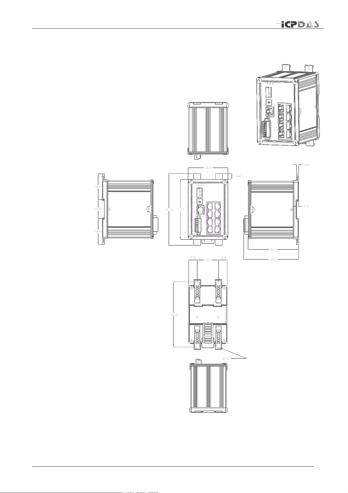
Dimensions
Front Panel
On Case Quick Guide
DIP Switch(SW1)
Rotary Switch (SW2)
Appearance
RS Series come with three form factors. One is stand alone with
industrial plastic case. The second one is stand alone with aluminum
case. And the other is modulized for ICPDAS PAC Series controllers
with industrial plastic case.
Overview
The RS Series is designed for easy installation, configuration and
maintenance. For hardware installation, we provide both easy DIN rail
mounting and wall mounting modes. To establish a simple redundant
ring, only 2 jumpers on the front panel to set to form a ring. It does
not depend on web configuration interface, neither a management
server.
All of connectors are well arranged on the front panel, so it is easier
to stack with other devices and to maintain in a small installation
space.
TDRS4050601
Page 18
Industrial Redundant Ring Switch – RS Series User Manual
10
48.01
35.40
48.01
Left Side View
Front View
Back View
Right Side View
Bottom View
Top View
131.42
110.11
72.59
10.65
3.50
3.50
95.20
103.40
40.00
16.30
16.30
122.92
Ø 4.50
Auxiliary View
Dimensions
TDRS4050601
Page 19
Industrial Redundant Ring Switch – RS Series User Manual
11
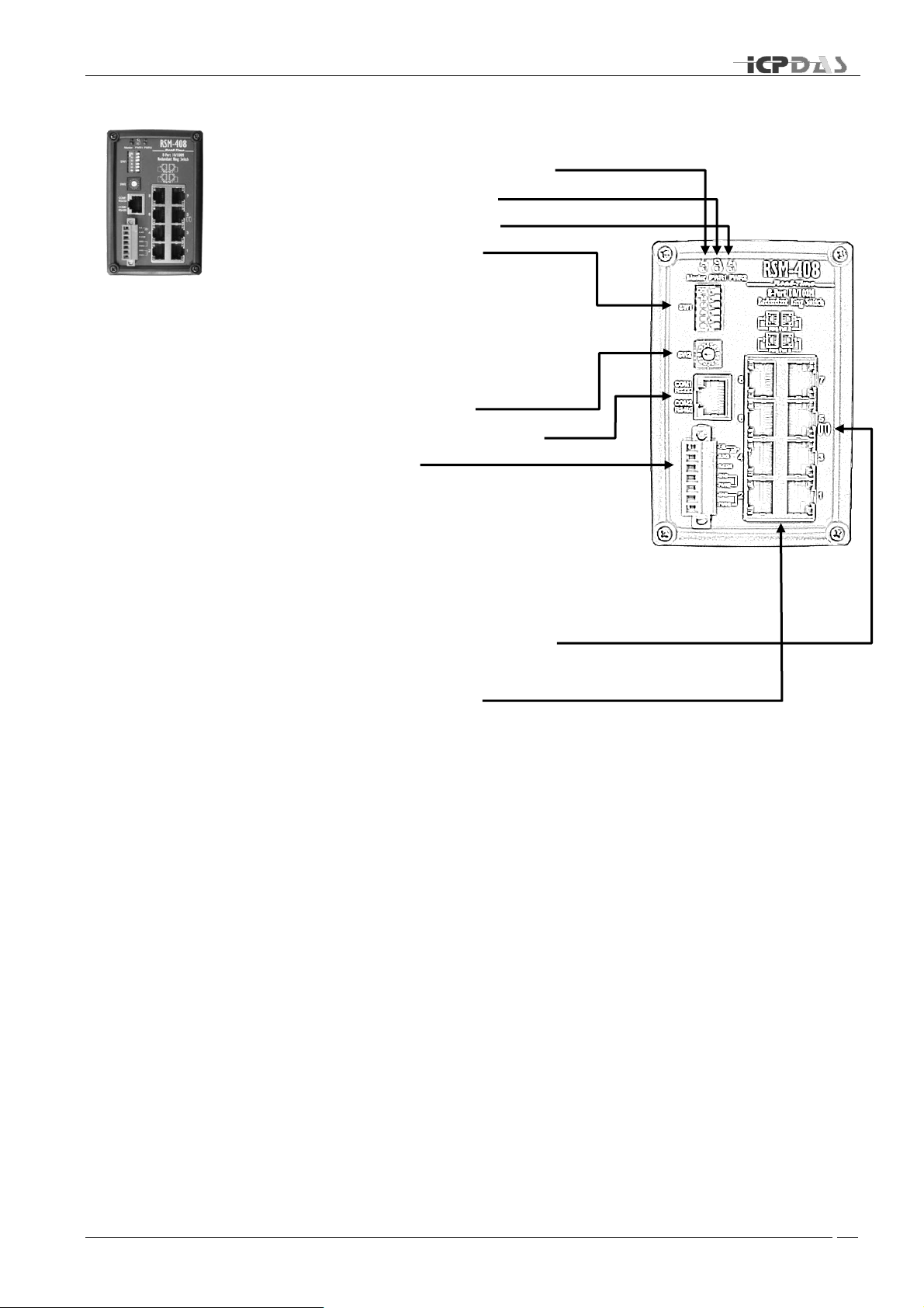
Front Panel
➊ Master switch LED indicator
❷ Power 1 LED indicator
❸ Power 2 LED indicator
❹ Switch jumper block
1. Ring / Normal Switch selecting jumper
2. Reset to default jumper
3. TPRT master setting jumper
4. Ring protocol selecting jumper
5. Enabling Ring 1 jumper
6. Enabling Ring 2 jumper
❺ Rotate jumper block
❻ Serial line via Ethernet port
❼ Terminal block
1. Frame Ground(F.G.)
2. Relay (R.NO)
3. Relay (R.COM)
4. Power 2 Grounding (GND)
5. Power 2 (PWR2)
6. Power 1 Grounding (GND)
7. Power 1 (PWR1)
❽ Interconnection port for 2
phase recovering coupling
❾ RJ-45 Ethernet ports
TDRS4050601
Page 20

Industrial Redundant Ring Switch – RS Series User Manual
12
On Case Quick Guide
The simple description of DIP and Rotate jumpers setting value, Quick Config Guide, has
been printed on both right and left hand side of front panel. After acquainted with RS
Series features, field engineers could deploy switches quickly by referencing Quick
Config Guide.
TDRS4050601
Page 21
Industrial Redundant Ring Switch – RS Series User Manual
13
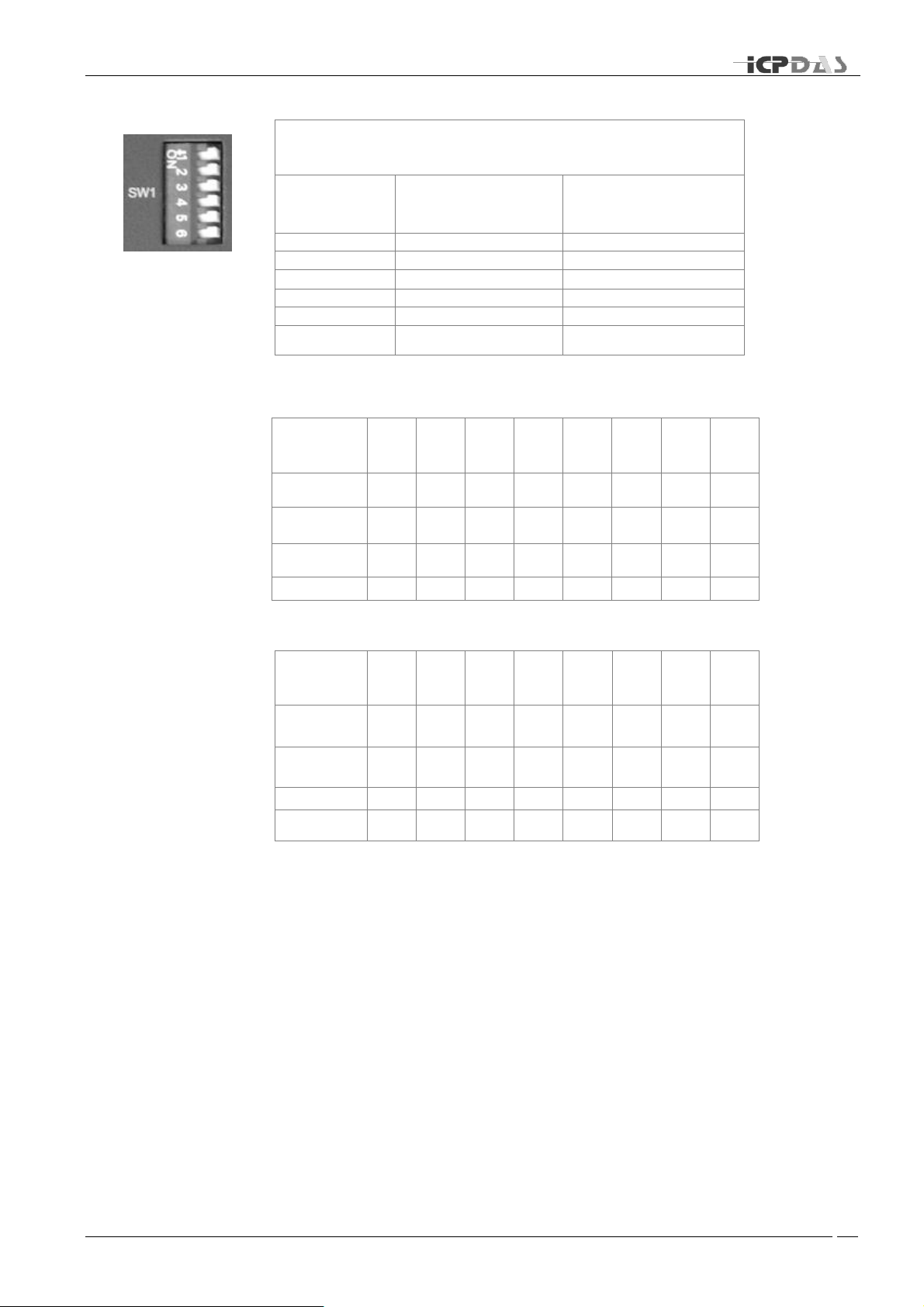
SW1 : DIP Switch Configuration
State
Jumper
OFF
ON
1
Redundancy mode
Tradition mode
2
Normal State
Default Setting
3
Primary Switch
Secondary Switch
4
Ring Protocol
STP Protocol
5
Disable Ring Pair 2
Enable Ring Pair 2
6
Disable Ring Pair 1
Enable Ring Pair 1
Roteray
SW position
F E D C B A 9
8
Recovery
Time
1.5s
1.4s
1.3s
1.2s
1.1s
1.0s
900
ms
800
ms
Forwarding
Delay
30s
28s
26s
24s
22s
20s
18s
16s
Hello Time
10s
10s
10s
10s
10s
10s
10s
10s
Max Age
40s
40s
40s
40s
40s
38s
34s
30s
Roteray
SW position
7 6 5 4 3 2 1
0
Recovery
Time
700
ms
600
ms
500
ms
400
ms
300
ms
200
ms
100
ms
N/A
Forwarding
Delay
14s
12s
10s
8s
6s
4s
4s
N/A
Hello Time
10s
10s
8s
6s
4s
2s
1s
N/A
Max Age
26s
22s
18s
14s
10s
6s
6s
N/A
DIP Switch (SW1)
Rotary Switch (SW2)
TDRS4050601
Page 22

Industrial Redundant Ring Switch – RS Series User Manual
14
DIN-Rail Mounting
Installation
Wall-Mounting Installation
Connecting Input Power
Connecting Output Relay
Connecting Ethernet Ports
Connecting Fiber Ports
Hardware Installation
For hardware installation, we provide both easy DIN rail mounting
and wall mounting modes.
Overview
RS Series support redundant power, output relay and enhanced
isolation to make device much robust. With ICP DAS patent DIN-Clip
design, the installation is just as easy as plugging power cord into
outlet.
®
TDRS4050601
Page 23

Industrial Redundant Ring Switch – RS Series User Manual
15
Up Clip
Down Clip
Push &
Clip
DIN-Rail Mounting Installation
With ICPDAS patent DIN-Clip
Following 3 steps completes installation.
➊
➋
Pull the down rail clip out.
Obliquing the switch and insert the upper rail clips onto the upper lip of the
DIN-rail track. Then push down the switch to fit into DIN rail as shown below.
®
design, DIN-Rail mounting installation becomes very easy.
➌
Push up down rail clip to lock the switch on the DIN rail.
TDRS4050601
Page 24
Industrial Redundant Ring Switch – RS Series User Manual
16
Pull out
Pull out
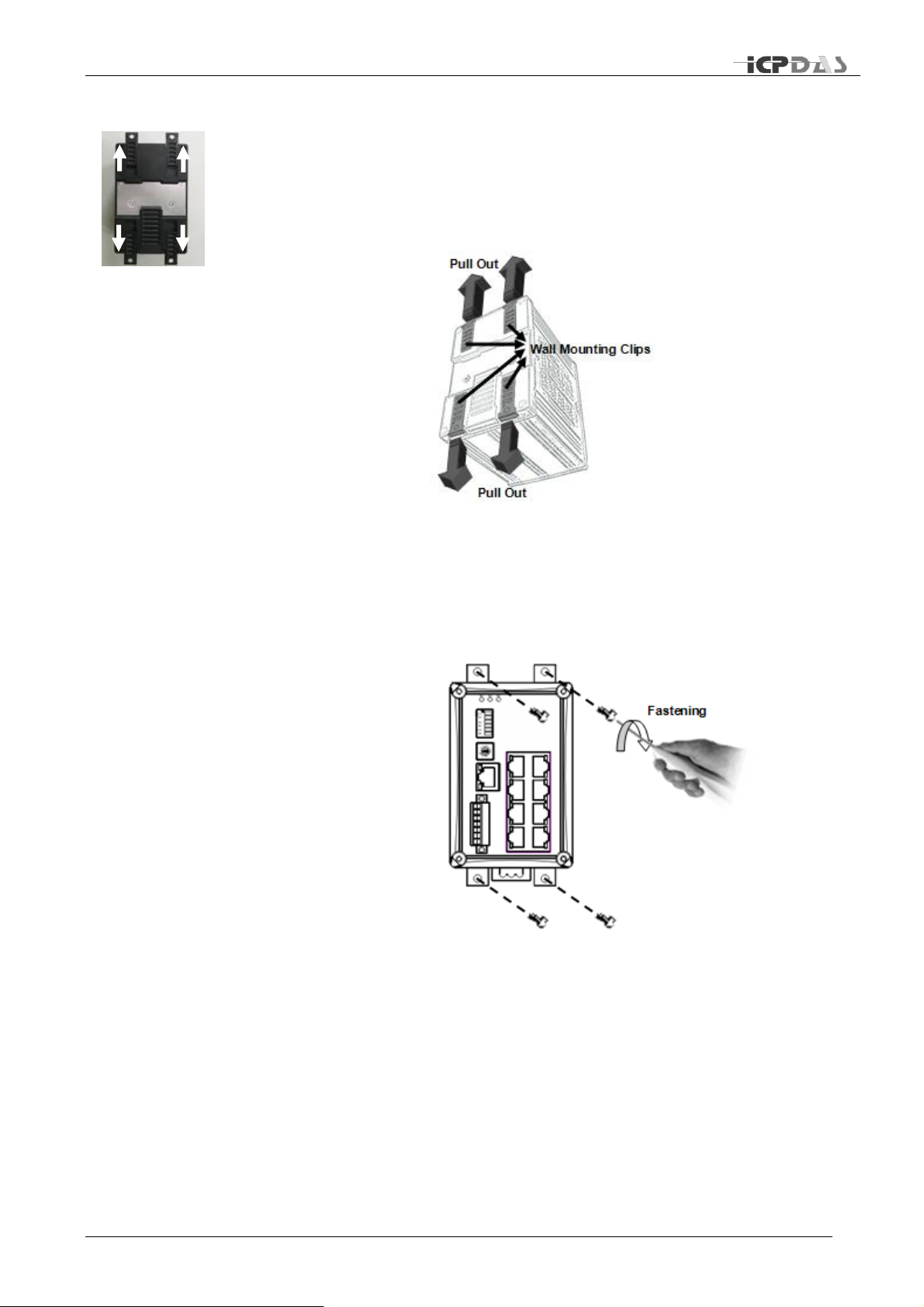
Wall-Mounting Installation
With ICP DAS patent DIN-Clip
Following 2 steps completes installation.
➊
Pull all wall mounting clip out.
®
design, Wall-Mounting installation becomes very easy.
➋
Use the slotted holes at each corner of the wall-mounting clip to attach the unit
to the wall or other flat surface. Then fasten it on the wall with screw.
TDRS4050601
Page 25

Industrial Redundant Ring Switch – RS Series User Manual
17
Connecting Input Power
IMPORTANT: It is good practice to turn off input and load power, and unplug the power
terminal block before making wire connections. Otherwise, your screwdriver blade can
inadvertently short your terminal connections to the grounded enclosure.
➊
Identify PWR1, GND, PWR2, GND contacts on terminal block. Then identify
power wire and ground wire.
➋
NOTE: For best reliability, please install both of PWN1 and PWN2 for power redundant.
Insert the wire of your DC supply or Battery supply into the PWN1 and/or
PWN2 contacts of the terminal block connector, and fastening the terminal
screws to prevent the wires from coming loose.
TDRS4050601
Page 26

Industrial Redundant Ring Switch – RS Series User Manual
18
Connecting Output Relay
The diagram of output relay:
➊
➋
Identify R.NO and R.COM contacts on terminal block.
Insert the relayed device such as a light bulb or a buzzer pair of wire, and
fastening the terminal screws to prevent the wires from coming loose.
TDRS4050601
Page 27

Industrial Redundant Ring Switch – RS Series User Manual
19
Connecting Ethernet Ports
RS Series includes all RJ-45 ports with automatic MDI/MDI-X crossover, and automatic
10/100Mbps data rate sensing for 10Base-T or 100Base-TX connections. Automatic
MDI/MDI-X crossover allows you to connect to other switches, hubs, or workstations,
without regard to using straight-through or crossover cabling. The following figures depict
the schematic diagram of straight-through and crossover cabling. Note that crossover
cables simply cross-connect the transmit lines at each end to the receive lines at the
opposite end.
Straight-through Cabling Schematic Crossover Cabling Schematic
Note that Ethernet cables use pins 1, 2, 3, and 6 of an 8-pin RJ45 connector. The signals
of these pins are converted by the automatic MDI-X function, as shown in the table
below:
Connect one side of an Ethernet cable into any switch port and connect the other side to
your attached device. The green LNK LED will light up when the cable is correctly
connected. Always make sure that the cables between the switches and attached devices
(e.g. switch, hub, or workstation) are less than 100 meters (328 feet).
Two switches are now up-linked together. If we change the up-link port manually at this
time, the MAC address table will change as well. After the MAC address table changes,
then the data can be transmitted between these two switches. This period of time is
called the MAC address table aging time. The switch‟s default aging time is 5 minutes,
which means that if you manually change the up-link port, you will need to wait up to 5
minutes before the data can be sent. If the aging time is too short, the MAC address table
will constantly refresh, resulting in excess consumption of switch computing resources.
For this reason, a longer aging time is recommended.
TDRS4050601
Page 28

Industrial Redundant Ring Switch – RS Series User Manual
20
Connecting Fiber Ports (only for models with fiber port)
The automatic MDI/MDI-X crossover function does not apply to fiber connections, as
these must be crossed over manually. To connect the fiber port on one switch to the fiber
port of another switch, simply cross-connect the transmit channel at each end to the
receive channel at the opposite end as illustrated in the figure below.
These models have two 100Base-FX ports with SC type connectors (in multi-mode and
single mode versions).
A fiber segment using single-mode cable must use 9/125 or 10/125 micrometer singlemode fiber cables. For single-mode, the connection distance can be up to 30 km.
A fiber segment using multi-mode must use 50 or 62.5/125 micrometer multi-mode fiber
cables. For multi-mode, the connection distance can be up to 2 km.
TDRS4050601
Page 29

Industrial Redundant Ring Switch – RS Series User Manual
21
One Ring Topology
Two Rings Coupling
Two Rings Coupling with
Two Phase Recovering
Configuration
This chapter provide basic techniques to form a redundant ring on
your demand.
Overview
To successfully form a robust industrial Ethernet network, the
designing of network pattern is the most important stage. A welldesigned network pattern could dramatically reduce the risk network
failure in critical situation.
TDRS4050601
Page 30

Industrial Redundant Ring Switch – RS Series User Manual
22
Backup Path
Active Path
Broken
One Ring Topology
A ring topology ensures the network having one more chance to keep connection alive
when any connection between 2 switches (nodes) has been broken inside the ring.
When we have formed a ring network, the focal point (master) will choose any one and
only one path as Redundant Path. It is actually inactive when the ring network works
properly. At the moment of any connection failure, the focal point will activates the
Redundant Path and fire alarm to output relay.
RS Series come with 2 ring pair by default. A ring pair can form a ring with other network
devices as below:
TDRS4050601
Page 31

Industrial Redundant Ring Switch – RS Series User Manual
23
6 5 4 3 2 1 Jumper
O F F F F F On/OFF
6 5 4 3 2 1 Jumper
O F F F F F On/OFF
6 5 4 3 2 1 Jumper
O F F F F F On/OFF
6 5 4 3 2 1 Jumper
O F F F F F On/OFF
6 5 4 3 2 1 Jumper
O O F F F F On/OFF
6 5 4 3 2 1 Jumper
O F F F F F On/OFF
6 5 4 3 2 1 Jumper
O F F F F F On/OFF
Ring 1
Ring 2
Two Rings Coupling
As a ring network is a small group of switches by geography, functionalities, or
subsystem, 2 or more rings could be coupled together to form a whole picture of industrial
network for an integrated system.
Single coupling point uses a switch to bridge 2 rings. Each ring still keeps original ring
topology features.
TDRS4050601
Page 32

Industrial Redundant Ring Switch – RS Series User Manual
24
6 5 4 3 2 1 Jumper
O F F F F F On/OFF
6 5 4 3 2 1 Jumper
O F F F F F On/OFF
6 5 4 3 2 1 Jumper
O F F F F F On/OFF
6 5 4 3 2 1 Jumper
F O F F F F On/OFF
6 5 4 3 2 1 Jumper
F O F F F F On/OFF
6 5 4 3 2 1 Jumper
O F F F F F On/OFF
6 5 4 3 2 1 Jumper
O F F F F F On/OFF
6 5 4 3 2 1 Jumper
O F F F F F On/OFF
6 5 4 3 2 1 Jumper
F O F O F F On/OFF
6 5 4 3 2 1 Jumper
F O F F F F On/OFF
Two Rings Coupling with Two Phase Recovering
Redundant coupling gives one more chance to keep connection alive when any
connection between 2 rings has been broken. It is much safe than Single Coupling, but it
takes 3 more switches to form Redundant Coupling.
Be sure to use port 5 (interconnection port) to form two phase recovering coupling and
only ring pair 2 can be used in this topology.
TDRS4050601
Page 33

Industrial Redundant Ring Switch – RS Series User Manual
25
No Power to the Switch
No Link Light on a Switch
Port
Master LED Keep on
Flashing
Troubleshooting
Overview
This chapter includes some information for general troubleshooting
as follows:
� No Power to the Switch
� No Link Light on a Switch Port
� Master LED Keep on Flashing
TDRS4050601
Page 34

Industrial Redundant Ring Switch – RS Series User Manual
26
No power to the switch.
• Check for faulty power cord.
• Check for loose or broken power connections.
• Check connections to ensure the power and ground are attached to the correct terminals.
• Check for power loss or power surges at the AC power outlet.
• Check Voltage of power coming into PWR1 or PWR2 to ensure it is within +10 - +30V DC.
• Ensure there are no shorts between power and ground.
If the above fails, contact support.
No link light on a switch port.
• Check for faulty or loose Cables(both ends). Visually inspect for loose or faulty connections at all
connectors and cables. If that does not correct the problem, try replacing the cable.
• Check the other device to see if it is powered up and operating correctly.
• Try moving the Ethernet cable that has the possible faulty connection to another port in the switch
and check for link light.
If the above fails, contact support.
Master LED keep on Flashing
• Check if Jumper 1 (on SW1) is switched to Tradition mode (ON), if you intend to use tradition
mode, keep this setting (Do not restart). If you would like to use redundancy mode, switch Jumper
1 to “OFF”, and restart the switch.
• Check if the topology is accurate.
• Check if network is functioning properly.
• Check if power supply is connected properly.
• Check if there is devices failure exit (including ring switch or other devices connected to the
switch)
• Check if MAC address is duplicated or illegal.
• Check if the length of recovery time (rtime) is adequate; if the recovery time is too short, set a
longer time interval.
• Check if the firmware is the newest version , please go to
http://www.icpdas.com/download/download-list.htm for downloading newest firmware version.
• Check if the firmware upgrading process is completed. If not, redo the upgrading sequence to
complete firmware upgrading process.
• If the problem is not solved, try the following steps to return to default settings:
switch Jumper 2(on SW1) to “ON” position → reset → switch Jumper 2 to “OFF” position →
reset
If the above fails, contact support.
TDRS4050601
Page 35

Industrial Redundant Ring Switch – RS Series User Manual
27
TELEPHONE
FAX
Taiwan
Hsinchu Headquarter
886-3-5973366
886-3-5973733
Banchiao Office
886-2-29500655
886-2-29500807
Hsintien Office
886-2-89192220
886-2-89192221
Taichung Office
886-4-23582815
886-4-23589114
Kaoshiung Office
886-7-2157688
886-7-2162602
USA
USA Office
1-310-517-9888 x101
1-310-517-0998
Europe
Europe Office
0049-711-9 97 37 75
0049-711- 9 97 37 84
Shanghai
Shanghai Office
8621-6247-1722
8621-6247-1725
Beijing
Beijing Office
8610-6298-0933
8610-6296-2890
Service Information
We sincerely hope that you never experience a problem with any ICP DAS product. If you
do need service, call ICP DAS at 886-3-5973366 and ask for Applications Engineering.
Our well-trained specialist will help you to quickly determine the source of the problem.
Many problems are easily resolved with a single phone call.
On-line support
HTTP ://WWW.ICPDAS.COM.TW/SEV ICES /SUPPORT.HT M
E-MAIL: S UPPORT@IC PDAS.COM
Contact Worldwide
TDRS4050601
Page 36

Industrial Redundant Ring Switch – RS Series User Manual
a
ANSI X3T9
Commonly referred to as FDDI. A local area network protocol that
operates at 100Mbps.
Asynchronous
Having a variable time interval between successive data or
information in the form of characters, operations, events.
Transmission in which the data or information is individually
synchronized or timed usually by start and stop bits (S/S).
Attenuation
A general term describing the loss of power between two points,
measured in decibels per kilometer (dB/km) at a specified wavelength
(nm).
Backbone
Network
A main or high speed transmission facility or medium usually designed
to connect lower speed channels or clusters of terminals. May
describe common carrier main transmission path.
Bandwidth
A range of frequencies available for signaling; the differences between
the highest and lowest frequencies of a band are expressed in (Hz).
Bridge
A device used to connect two separate LANs or used to divide a large
LAN into smaller LANs. Each LAN acts as its own LAN, but uses a
bridge device to communicate from one LAN to another.
Bus
Path or channel, usually electrical, with one or more conductors,
where all devices are able to receive all transmissions at the same
time.
Counter-Rotating
Ring
Aka. Self-Healing Ring; has two physical transmission lines or rings
with transmitting and receiving signals in each ring travelling in
opposite directions. If the line or a device along the ring fails, the ring
re-anneals by bypassing the device and or line and forms with the
other ring to form a new single ring.
Crosstalk
The unwanted transfer of energy from the disturbing circuit to another
called the disturbed circuit. Usually from an adjacent analog channel.
Dispersion
The spreading of light pulses that takes place in multimode fiber optic
transmission. Dispersion limits the potential transmission distance
because the spread out light pulses reach the destination at different
times making the signal unreadable.
Ethernet
Product name for one of the first popular LAN technologies, later
standardized as IEEE 802.3.
Fiber Optic Cable
Thin filaments of glass or other transparent material sheathed in an
insulator through which a light beam may be transmitted for long
distances by means of multiple internal reflections. A waveguide used
to transmit digital information.
Flow Control
A method for a receiver to control the information flow from a
transmitter. It eliminates data overflow at the receiver.
Appendix A
Glossaries
TDRS4050601
Page 37

Industrial Redundant Ring Switch – RS Series User Manual
b
Full Duplex
A communication method where both ends can transmit and receive
simultaneously.
Half Duplex
A communication method where one end transmits while the other
end receives, then reverses the process.
Hub
A device for local area networks (LANs) that is used to interconnect
multiple devices over an internal bus.
Jitter
Aka. phase jitter, caused by power line harmonics and perceived in
the form of minor phase changes.
Multi-Drop Line
Aka. Multipoint Line, a data link supporting multiple DTE connections,
usually with one DTE controlling the link by polling the other DTEs for
input and addressing output to the other DTEs. Utilizing frequency
division or statistical MUX, a multipoint line can support multiple
independent point-to-point channels.
Multimode fiber
An optical fiber that supports more than one propagating mode of light
propagation.
Multiplexer
Aka. or Multiplexor or Mux,. A device using several communications
channels at the same time, transmits and receives messages and
controls communications lines, may be a microprocessor.
Node
A network-connected device, such as a server or PC.
Order Wire
Voice channel used to communicate between two locations.
Packet
A grouping of data, usually consisting of data and an address header
prior to being sent over a network.
Point-of
Presence (POP)
The physical access location within a specific location of the long
distance or common carrier.
Polling
The method used for terminal to controller communications. The
controller systematically asks for each terminal if it needs to transmit
to the controller.
Protocol
A set of rules for data communication. All devices communicating
together must adhere to the same rules.
Router
Similar to a bridge but provides more complex and flexible networking
support. It usually also supports WANs.
Single mode fiber
An optical fiber that supports only one mode of light propagation
above the cutoff wavelength.
Star
Network in which all terminals are connected through a single point or
node, such as a star coupler.
Synchronous
Transmission
Having a constant time interval between successive bits of data or
information.
Time Division
Multiplexing
A type of multiplexer that allocates a defined amount of backbone
bandwidth for each connected device.
Time Slot
Unit of backbone bandwidth allocated for each port.
TDRS4050601
Page 38

Industrial Redundant Ring Switch – RS Series User Manual
c
Token Ring
A LAN topology where a control packet or token is passed from
station to station in sequential order. The stations wishing to access
must wait for the token before transmitting data, in the token ring the
next logical station is also the next physical station.
Virtual Path
A software-controlled point-to-point connection between two devices
or segments.
TDRS4050601
Page 39

Industrial Redundant Ring Switch – RS Series User Manual
d
Ethernet switch type
Intelligent store & forward
RJ45 ports (shielded)
10/100BaseT(x)
RJ45 speed (auto-negotiating)
10 Mbps or 100 Mbps
RJ45 auto-mdi/mdi-x
All 5 ports
Ethernet protocols supported
All standard IEEE 802.3
Memory bandwidth
3.2 Gbps
Completely compliant
IEEE 802.3, IEEE 802.3u, IEEE802.3x
Full or half duplex operation
Auto-sensing
MAC addresses supported
2K
Ethernet isolation
1500 VRMS 1 minute
Required supply voltage
+10 ~ +30 VDC
Power input isolation
1KV
Power consumption
(Redundant input terminals)
5 W
(typical - all ports active at 100 Mbps)
Operating temperature
-30 ~ +75°C
Storage temperature
-40 ~ +85°C
Vibration
EN 50155 and EN11373.
EMC immunity
EN61326-1 (EN61000-4-2, 3, 4, 5, 6)
Appendix B
Specifications
TDRS4050601
Page 40

Industrial Redundant Ring Switch – RS Series User Manual
e
Address
Status
Address
10000
Ring Pair 1 Enable
10004
Power 1 Fail
10001
Ring Pair 2 Enable
10005
Power 2 Fail
10002
0 : Ring Protocol
1 : Spanning Tree Protocol
10006
Relay output
10003
Secondary switch
10007
Master
Address
Status
Address
10008
Link on port 1
10016
Link on port 9
10009
Link on port 2
10017
Link on port 10
10010
Link on port 3
10018
Link on port 11
10011
Link on port 4
10019
Link on port 12
10012
Link on port 5
10020
Link on port 13
10013
Link on port 6
10021
Link on port 14
10014
Link on port 7
10022
Link on port 15
10015
Link on port 8
10023
Link on port 16
Address
Status
Address
10024
Port 1 is forwarding
10032
Port 9 is forwarding
10025
Port 2 is forwarding
10033
Port 10 is forwarding
10026
Port 3 is forwarding
10034
Port 11 is forwarding
10027
Port 4 is forwarding
10035
Port 12 is forwarding
10028
Port 5 is forwarding
10036
Port 13 is forwarding
10029
Port 6 is forwarding
10037
Port 14 is forwarding
10030
Port 7 is forwarding
10038
Port 15 is forwarding
10031
Port 8 is forwarding
10039
Port 16 is forwarding
Address
Status
Address
10040
Port 1 lose pair port
10048
Port 9 lose pair port
10041
Port 2 lose pair port
10049
Port 10 lose pair port
10042
Port 3 lose pair port
10050
Port 11 lose pair port
10043
Port 4 lose pair port
10051
Port 12 lose pair port
10044
Port 5 lose pair port
10052
Port 13 lose pair port
10045
Port 6 lose pair port
10053
Port 14 lose pair port
10046
Port 7 lose pair port
10054
Port 15 lose pair port
10047
Port 8 lose pair port
10055
Port 16 lose pair port
Appendix C
Modbus Table
Switch Status
Link Status
Forwarding Status
Communication Status
TDRS4050601
Page 41

Industrial Redundant Ring Switch – RS Series User Manual
f
Parameter
Description
command
Please provide the name of the command that you
want detail information about.
Appendix D
Console Command Reference
?,help [command]: Help
reset
default
ip,setip
mask,setmask
gateway,setgateway
mac,seteid
netid [id number]
lmask [mask value]
cmask [mask value]
smask [mask value]
lvalue
cvalue
svalue
hmivalue
rtime [time]
ftime [time]
mtime [time]
htime [time]
com1 [baudrate][databit][parity][stopbit]
com2 [baudrate][databit][parity][stopbit]
?,help [command]
Description
Both “help” and “?” display a list of available commands, if parameter is not specified.
The [command] parameter is used to see detail information for a specific command.
Parameters
TDRS4050601
Page 42

Industrial Redundant Ring Switch – RS Series User Manual
g
Example:
reset
Description
The reset command will initiate Ring Switch a self-restart. All current setting values
remain intact.
TDRS4050601
Page 43

Industrial Redundant Ring Switch – RS Series User Manual
h
Example:
default
Description
The default command will restore all settings to factory default values.
Current factory default values are as follow:
COM1:baudrate 115200,8bit,none patity check, 1 stopbit
COM2:baudrate 115200,8bit,none patity check, 1 stopbit
link mask:0
communication mask:0x1f
status mask:0x3
netid:1
mac: factory-set unique MAC address
ip:192.168.255.1
mask:255.255.255.0
Example:
TDRS4050601
Page 44

Industrial Redundant Ring Switch – RS Series User Manual
i
ip,setip
Description
If no IP address is specified, the “ip” or “setip” command will display current IP
address. To assign an IP address for TCP/IP, please input IP address in the form of
“ip1.ip2.ip3.ip4”(each field contains a value in the range 0 – 255).
Example:
mask,setmask
Description
If no mask address is specified, the “mask” or “setmask” command will display
current mask address. To assign a mask address for TCP/IP, please input mask
address in the form of “m1.m2.m3.m4”(each field contains a value in the range 0 –
255).
Example:
gateway,setgateway
Description
If no gateway IP address is specified, the “gateway” or “setgateway” command will
display current gateway address. Note that if there exits a check sum error, an error
message will alert. To assign a gateway address for TCP/IP, please input gateway
IP address in the form of “ip1.ip2.ip3.ip4” (each field contains a value in the range
0 – 255).
TDRS4050601
Page 45

Industrial Redundant Ring Switch – RS Series User Manual
j
Parameter
Description
id number
Provides the ID number that you want to set up for
Modbus Net ID.
Example:
mac,seteid
Description
If no MAC address is specified, the “mac” or “seteid” command will display current
MAC address. To assign a MAC address for Ethernet, please input MAC address in
the form of “e1:e2:e3:e4:e5:e6”.
Example:
Note: Each RS is shipped from the factory with a unique MAC address. DO NOT
change this address unless you have a good reason to do so. If you do change the
address, remember to make a note of this factory-set MAC address and keep it in a
safe place.
netid [id number]
Description
If Net ID of Modbus is not specified, the “netid” command will display current ID
number of Modbus. The command parameter [id number] is used to assign a
specific ID number for Modbus Net ID.
Parameters
Example:
TDRS4050601
Page 46

Industrial Redundant Ring Switch – RS Series User Manual
k
Parameter
Description
mask value
Provides the mask value that you want to specify to
configure status of relay when link loss occurs
lmask [mask value]
Description
This command enables you to configure relay output activation status when there is
link loss occurring on port(s). The ports are corresponding to the 8 mask bits, bit 0
corresponds to port 1, etc. (Please refer to Appendix G, Table – 1.) If the mask bit of
that port(s) is specified by being set up as 1, when there is a link loss occurring on
that port(s), relay output will be activated. The mask value is in hexadecimal format
that represents the 8 bits corresponding binary numbers, it can be either in the form
of initiating “0X” plus a suffix of the hexadecimal number or eliminating “0X”; simply
the hexadecimal number itself. If a mask value is not specified, the “lmask”
command will display previous assigned mask value.
To assign a mask value for activating relay output when there is link loss occurring
on the port(s), please refer to Appendix G, Table – 2.
Parameters
Example:
cmask [mask value]
Description
This command enables you to configure relay output activation status when there is
communication loss occurring on port(s). The ports are corresponding to the 8 mask
bits, bit 0 corresponds to port 1, etc. (Please refer to Appendix G, Table – 3.) If the
mask bit of that port(s) is specified by being set up as 1, when there is a
communication loss occurring on that port(s), relay output will be activated. The
mask value is in hexadecimal format that represents the 8 bits corresponding binary
numbers, it can be either in the form of initiating “0X” plus a suffix of the hexadecimal
number or eliminating “0X”; simply the hexadecimal number itself. If a mask value is
not specified, the “cmask” command will display previous assigned mask value.
To assign a mask value for activating relay output when there is communication loss
occurring on the port(s), please refer to Appendix G, Table – 4.
TDRS4050601
Page 47

Industrial Redundant Ring Switch – RS Series User Manual
l
Parameter
Description
mask value
Provides the mask value that you want to specify for
the communication loss relay output
Example:
smask [mask value]
Description
This command enables you to configure relay output activation status when there is
power fail occurring on power 1 or power 2, or when the switch is being selected as
the master switch.
Bit 0 corresponds to Power1, bit 1 corresponds to Power 2 and bit 3 corresponds to
master switch indicator. If the mask bit of that power(s)(bit 0 and bit 1) or master
switch indicator (bit 2) is specified by being set up as 1, when there is a power fail
occurring on Power(s), or when the switch is selected as master switch, the
corresponding relay output will be activated.
The mask value is in hexadecimal format that represents the 8 bits corresponding
binary numbers, it can be either in the form of initiating “0X” plus a suffix of the
hexadecimal number or eliminating “0X”; simply the hexadecimal number itself. If a
mask value is not specified, the “smask” command will display previous assigned
mask value.
To assign a mask value for activating relay output when there is communication loss
occurring on the port(s), please refer to Appendix G, Table – 5.
Parameters
Example:
TDRS4050601
Page 48

Industrial Redundant Ring Switch – RS Series User Manual
m
lvalue
Description
This command enables you to read link status showing by a hexadecimal number
that represents the 8 bits corresponding binary numbers. Bit 0 corresponds to port 1,
etc. (Please refer to Appendix G, Table – 6). If there is link loss occurring on port(s),
the corresponding bit(s) will be set up as 1. You would be able to clarify current link
status by this returned lvalue in hexadecimal format, please refer to Appendix G,
Table – 7.
Example:
cvalue
Description
This command enables you to read communication status showing by a
hexadecimal number that represents the 8 bits corresponding binary numbers. Bit 0
corresponds to port 1, etc. (Please refer to Appendix G, Table – 8). If there is a
communication loss occurring on port(s),the corresponding bit(s) will be set up as 1.
You would be able to clarify current communication status by this returned cvalue in
hexadecimal format, please refer to Appendix G, Table – 9.
Example:
svalue
Description
This command enables you to read system status showing by a hexadecimal
number that represents the 8 bits corresponding binary numbers, please refer to
Appendix G, Table – 10.
You would be able to clarify current system status by this returned svalue in
hexadecimal format, please refer to Appendix G, Table – 11 .
Example:
TDRS4050601
Page 49

Industrial Redundant Ring Switch – RS Series User Manual
n
hmivalue
Description
This command enables you to read Switch 1 (SW1) and Switch 2 (SW2) settings on
HMI by returning a message in the form of “HMI setting (state) DIPSW,RotarySW “.
You would be able to clarify current HMI setting status by this returning message.
SW1 contains 6 jumpers, each jumper (Jumper 3 to Jumper 6) corresponds to one
bit. (Please refer to Appendix G, Table – 12.) It is a DIP toggle switch with two
possible positions -- on or off. Each position indicates one configuration state.
(Please refer to Appendix G, Table – 13.) The returned DIPSW value is a
hexadecimal number corresponding to the states of the Jumpers. (Please refer to
Appendix G, Table – 14.)
The returned tag “state” indicates current state of Jumper 2, if it‟s on “on” position,
current configuration will be set as default state and a “default” message will be
displayed, if it‟s on “off” position - current configuration will be set as normal state
and a “normal” message will be displayed.
SW2 is a 16 position rotary switch. When the arm of SW2 is switched to position “0”,
you would be able to set up specific values for recovery time(rtime), forward
delay(ftime) , maximum age(mtime), and hello time(htime) manually. If the position is
on positions other than “0” (“1” to “F”), a set of preset values will be applied. The
returned RotarySW value indicates the current position of SW2. Please refer to
Appendix G, Table – 15, and sections of rtime, ftime, mtime and htime for more
detail information.
Example:
rtime [time]
Description
Recovery time is the length of time it takes to return back to normal operation after
an error or other failure has occurred. This command enables you to set up the
recovery time in millisecond (ms).
To setup the recovery time manually, you are required to switch the SW1 Jumper 4
to “off” position (applying Ring protocol), and SW2 to position „0‟ (if the SW2 position
is not on „0‟, a preset value will be applied according to its corresponding position,
please refer to Appendix G, Table – 15. If SW1 jumper 4 is not on “off” position; that
is, not applying ring protocol, rtime is not applicable)
After each new rtime setting, you would need to reset the switch to make new setting
effective.
Note: rtime command returns the following message: “recovery time x(y) ms.” “x”
( switch value) indicates the rtime value set by console command, “y” (operating
TDRS4050601
Page 50

Industrial Redundant Ring Switch – RS Series User Manual
o
Parameter
Description
time
Provides the time interval(ms) that you want to set
up as the recovery time
Parameter
Description
time
Provides the time interval(ms) that you want to set
up as the forward time
value) indicates the actual operating value. When applying redundancy mode, the
actual rtime value can be only set up by modifying master switch rtime value.
Parameters
Example:
Use the following function to calculate an adequate rtime:
rtime = [Round(0.3*(N+1))]*100 ms
N: number of switches
Example:
If there are 5 switches(including master switch), the adequate
rtime will be:
[Round(0.3*(5+1))]*100 = Round(1.8) *100 =2*100 =200 ms
ftime [time]
Description
This command enables you to set up the spanning tree bridge forward delay in
milliseconds(ms) . Forward delay is the time interval spent waiting to change a port
from its spanning tree pre-forwarding state to a forwarding state. This is necessary
because every bridge on the network should ensure no loop is formed before
allowing the port to forward packets.
To setup the forward time manually, you are required to switch the SW1 Jumper 4 to
“on” position (applying STP protocol), and SW2 to position „0‟ (if the SW2 position is
not on „0‟, a preset value will be applied according to its corresponding position,
please refer to Appendix G, Table – 15. If SW1 jumper 4 is not on “on” position; that
is, not applying STP protocol, ftime is not applicable)
Parameters
Example:
TDRS4050601
Page 51

Industrial Redundant Ring Switch – RS Series User Manual
p
Parameter
Description
time
Provides the time interval(ms) that you want to set
up as the maximum time
Parameter
Description
time
Provides the time interval(ms) that you want to set
up as the hello time
mtime [time]
Description
This command enables you to setup the spanning tree bridge maximum age in
milliseconds(ms) . Max age is the maximum time a bridge waits without receiving
spanning tree configuration messages before attempting a reconfiguration.
To setup the maximum time manually, you are required to switch the SW1 Jumper 4
to “on” position (applying STP protocol), and SW2 to position „0‟ (if the SW2 position
is not on „0‟, a preset value will be applied according to its corresponding position,
please refer to Appendix G, Table – 15. If SW1 jumper 4 is not on “on” position; that
is, not applying STP protocol, mtime is not applicable)
Parameters
Example:
htime [time]
Description
This command enables you to set the spanning tree bridge hello time in millisecond
(ms). Hello time is the interval between transmission of spanning tree configuration
messages. All bridges send configuration messages during reconfiguration to select
the designated root bridge (in this case, the switch port).
To setup the hello time manually, you are required to switch the SW1 Jumper 4 to
“on” position (applying STP protocol), and SW2 to position „0‟ (if the SW2 position is
not on „0‟, a preset value will be applied according to its corresponding position,
please refer to Appendix G, Table – 15. If SW1 jumper 4 is not on “on” position; that
is, not applying STP protocol, htime is not applicable)
Parameters
Example:
TDRS4050601
Page 52

Industrial Redundant Ring Switch – RS Series User Manual
q
Parameter
Description
baudrate
Provides the baud rate (300 or 600 or 1200 or 2400
or 4800 or 9600 or 19200 or 38400 or 57600 or
115200)for your usage, default value is 115200
databit
Provides the data bit value(7 or 8), default value is 8
parity
Provides the parity check type, none k(0) , even (1),
odd (2):, default value is 0.
stopbit
Provides the stop bit(1 or 2), default value is 1.
Note: if you intend to set up any one of the recovery time, forward time, max age, or
hello time manually by using console commands, you are required to set up these
values all together by using the corresponding console commands, too. If you do not
assign specific values for these settings, they will become preset values (or default
values if no values were previously assigned)
com1 [baudrate][databit][parity][stopbit]
Description
The first serial port Com1 is assigned for RS232. This command enables you to set
up the transmission speed(baudrate),data bit(databit), parity check type (parity) and
stop bit(stopbit).
The transmission speed parameter [baudrate] allows the following settings: 300, 600,
1200, 2400, 4800, 9600, 19200, 38400, 57600, and 115200. The port speed and
device speed must match.
The number of data bits can be 7 (for true ASCII) or 8 (for any kind of data, as this
matches the size of a byte),
The parity check code can be set to none (0), even (1), or odd (2). None(0) means
that no parity bit is sent at all. Even (1) means applying even parity check, each set
of transmitted bits must have an even number of set bits. Odd (2) means applying
odd parity check, each set of transmitted bits must have an odd number of set bits.
Stop bit is used in asynchronous communications to indicate the end of a piece of
data.
Parameters
Example:
TDRS4050601
Page 53

Industrial Redundant Ring Switch – RS Series User Manual
r
Parameter
Description
baudrate
Provides the baud rate (300 or 600 or 1200 or 2400
or 4800 or 9600 or 19200 or 38400 or 57600 or
115200)for your usage, default value is 115200
databit
Provides the data bit value(7 or 8), default value is 8
parity
Provides the parity check type, none k(0) , even (1),
odd (2):, default value is 0.
stopbit
Provides the stop bit(1 or 2), default value is 1.
com2 [baudrate][databit][parity][stopbit]
Description
The second serial port Com2 is assigned for RS485. This command enables you to
set up the transmission speed(baudrate),data bit(databit), parity check type (parity)
and stop bit(stopbit).
The transmission speed parameter [baudrate] allows the following settings: 300, 600,
1200, 2400, 4800, 9600, 19200, 38400, 57600, and 115200. The port speed and
device speed must match.
The number of data bits can be 7 (for true ASCII) or 8 (for any kind of data, as this
matches the size of a byte),
The parity check code can be set to none (0), even (1), or odd (2). None(0) means
that no parity bit is sent at all. Even (1) means applying even parity check, each set
of transmitted bits must have an even number of set bits. Odd (2) means applying
odd parity check, each set of transmitted bits must have an odd number of set bits.
Stop bit is used in asynchronous communications to indicate the end of a piece of
data.
Parameters
Example:
TDRS4050601
Page 54

Industrial Redundant Ring Switch – RS Series User Manual
s
0
No protection (Sometimes X)
1
Protected against solid objects up to 50mm³
2
Protected against solid objects up to 12mm³
3
Protected against solid objects up to 2.5mm³
4
Protected against solid objects up to 1mm³
5
Protected against dust, limited ingress (no harmful deposit)
6
Totally protected against dust
0
No protection (Sometimes X)
1
Protection against vertically falling drops of water (e.g. condensation)
2
Protection against direct sprays of water up to 15 degrees from vertical
3
Protection against direct sprays of water up to 60 degrees from vertical
4
Protection against water sprayed from all directions - limited ingress
permitted
5
Protected against low pressure jets of water from all directions - limited
ingress permitted
6
Protected against low pressure jets of water, limited ingress permitted (e.g.
ship deck)
7
Protected against the effect of immersion between 15cm and 1m
8
Protected against long periods of immersion under pressure
Appendix E
Ingress Protection (IP)
An IP number is used to specify the environmental protection of enclosures around
electronic equipment. These ratings are determined by specific tests.
The IP number is composed of two numbers, the first referring to the protection against
solid objects and the second against liquids. The higher the number is, the better the
protection.
Note: All ICP DAS RS Series devices are manufactured and tested to IEC IP51
standards.
First Number
Second Number
TDRS4050601
Page 55

Industrial Redundant Ring Switch – RS Series User Manual
t
KA-52F
24V/1A output power supply
DIN-KA52F
24V/1A output power supply with DIN-Rail Mount
Appendix F
Accessories
Power Supply (KA-52F/DIN-KA52F)
Features & Specifications
Input Range : 100~250AC
Input Frequency : 50Hz to 60 Hz
Output : 24Vdc/1Amp max.
Output Power : 25Watts
Operating Temperature:0 to 70℃
Storage Temperature : -40 to 85℃
Demension :
65 x 105 x 36mm (KA-52F)
68 x 107 x 50mm (DIN-KA52F)
Part No. Information
TDRS4050601
Page 56

Industrial Redundant Ring Switch – RS Series User Manual
u
Bit 7
Bit 6
Bit 5
Bit 4
Bit 3
Bit 2
Bit 1
Bit 0
Port 8
Port 7
Port 6
Port 5
Port 4
Port 3
Port 2
Port 1
1
on 1 on 1 on 1 on 1 on 1 on 1 on 1 on 0 off 0 off 0 off 0 off 0 off 0 off 0 off 0 off
Activate relay output when there
is a link loss occurring on port(s):
Corresponding
8 bits binary
numbers
Mask
value
N/A
00000000
0X0 or 0
1
00000001
0X1 or 1
2
00000010
0X2 or 2
1 or 2
00000011
0X3 or 3
3
00000100
0X4 or 4
1 or 3
00000101
0X5 or 5
2 or 3
00000110
0X6 or 6
1 or 2 or 3
00000111
0X7 or 7
4
00001000
0X8 or 8
1 or 4
00001001
0X9 or 9
2 or 4
00001010
0Xa or a
1 or 2 or 4
00001011
0Xb or b
3 or 4
00001100
0Xc or c
1 or 3 or 4
00001101
0Xd or d
2 or 3 or 4
00001110
0Xe or e
1 or 2 or 3 or 4
00001111
0Xf or f
5
00010000
0X10 or 10
1 or 5
00010001
0X11 or 11
2 or 5
00010010
0X12 or 12
1 or 2 or 5
00010011
0X13 or 13
3 or 5
00010100
0X14 or 14
1 or 3 or 5
00010101
0X15 or 15
2 or 3 or 5
00010110
0X16 or 16
1 or 2 or 3 or 5
00010111
0X17 or 17
4 or 5
00011000
0X18 or 18
1 or 4 or 5
00011001
0X19 or 19
2 or 4 or 5
00011010
0X1a or 1a
1 or 2 or 4 or 5
00011011
0X1b or 1b
3 or 4 or 5
00011100
0X1c or 1c
1 or 3 or 4 or 5
00011101
0X1d or 1d
2 or 3 or 4 or 5
00011110
0X1e or 1e
1 or 2 or 3 or 4 or 5
00011111
0X1f or 1f
6
00100000
0X20 or 20
1 or 6
00100001
0X21 or 21
2 or 6
00100010
0X22 or 22
1 or 2 or 6
00100011
0X23 or 23
3 or 6
00100100
0X24 or 24
1 or 3 or 6
00100101
0X25 or 25
2 or 3 or 6
00100110
0X26 or 26
1 or 2 or 3 or 6
00100111
0X27 or 27
Appendix G
Tables
Table – 1 Corresponding bits and ports (for lmask command)
Table – 2 Assign mask value for activating relay output when there is link loss occurring on the port(s)
TDRS4050601
Page 57

Industrial Redundant Ring Switch – RS Series User Manual
v
4 or 6
00101000
0X28 or 28
1 or 4 or 6
00101001
0X29 or 29
2 or 4 or 6
00101010
0X2a or 2a
1 or 2 or 4 or 6
00101011
0X2b or 2b
3 or 4 or 6
00101100
0X2c or 2c
1 or 3 or 4 or 6
00101101
0X2d or 2d
2 or 3 or 4 or 6
00101110
0X2e or 2e
1 or 2 or 3 or 4 or 6
00101111
0X2f or 2f
5 or 6
00110000
0X30 or 30
1 or 5 or 6
00110001
0X31 or 31
2 or 5 or 6
00110010
0X32 or 32
1 or 2 or 5 or 6
00110011
0X33 or 33
3 or 5 or 6
00110100
0X34 or 34
1 or 3 or 5 or 6
00110101
0X35 or 35
2 or 3 or 5 or 6
00110110
0X36 or 36
1 or 2 or 3 or 5 or 6
00110111
0X37 or 37
4 or 5 or 6
00111000
0X38 or 38
1 or 4 or 5 or 6
00111001
0X39 or 39
2 or 4 or 5 or 6
00111010
0X3a or 3a
1 or 2 or 4 or 5 or 6
00111011
0X3b or 3b
3 or 4 or 5 or 6
00111100
0X3c or 3c
1 or 3 or 4 or 5 or 6
00111101
0X3d or 3d
2 or 3 or 4 or 5 or 6
00111110
0X3e or 3e
1 or 2 or 3 or 4 or 5 or 6
00111111
0X3f or 3f
7
01000000
0X40 or 40
1 or 7
01000001
0X41 or 41
2 or 7
01000010
0X42 or 42
1 or 2 or 7
01000011
0X43 or 43
3 or 7
01000100
0X44 or 44
1 or 3 or 7
01000101
0X45 or 45
2 or 3 or 7
01000110
0X46 or 46
1 or 2 or 3 or 7
01000111
0X47 or 47
4 or 7
01001000
0X48 or 48
1 or 4 or 7
01001001
0X49 or 49
2 or 4 or 7
01001010
0X4a or 4a
1 or 2 or 4 or 7
01001011
0X4b or 4b
3 or 4 or 7
01001100
0X4c or 4c
1 or 3 or 4 or 7
01001101
0X4d or 4d
2 or 3 or 4 or 7
01001110
0X4e or 4e
1 or 2 or 3 or 4 or 7
01001111
0X4f or 4f
5 or 7
01010000
0X50 or 50
1 or 5 or 7
01010001
0X51 or 51
2 or 5 or 7
01010010
0X52 or 52
1 or 2 or 5 or 7
01010011
0X53 or 53
3 or 5 or 7
01010100
0X54 or 54
1 or 3 or 5 or 7
01010101
0X55 or 55
2 or 3 or 5 or 7
01010110
0X56 or 56
1 or 2 or 3 or 5 or 7
01010111
0X57 or 57
4 or 5 or 7
01011000
0X58 or 58
1 or 4 or 5 or 7
01011001
0X59 or 59
2 or 4 or 5 or 7
01011010
0X5a or 5a
1 or 2 or 4 or 5 or 7
01011011
0X5b or 5b
3 or 4 or 5 or 7
01011100
0X5c or 5c
1 or 3 or 4 or 5 or 7
01011101
0X5d or 5d
2 or 3 or 4 or 5 or 7
01011110
0X5e or 5e
1 or 2 or 3 or 4 or 5 or 7
01011111
0X5f or 5f
6 or 7
01100000
0X60 or 60
1 or 6 or 7
01100001
0X61 or 61
2 or 6 or 7
01100010
0X62 or 62
TDRS4050601
Page 58

Industrial Redundant Ring Switch – RS Series User Manual
w
1 or 2 or 6 or 7
01100011
0X63 or 63
3 or 6 or 7
01100100
0X64 or 64
1 or 3 or 6 or 7
01100101
0X65 or 65
2 or 3 or 6 or 7
01100110
0X66 or 66
1 or 2 or 3 or 6 or 7
01100111
0X67 or 67
4 or 6 or 7
01101000
0X68 or 68
1 or 4 or 6 or 7
01101001
0X69 or 69
2 or 4 or 6 or 7
01101010
0X6a or 6a
1 or 2 or 4 or 6 or 7
01101011
0X6b or 6b
3 or 4 or 6 or 7
01101100
0X6c or 6c
1 or 3 or 4 or 6 or 7
01101101
0X6d or 6d
2 or 3 or 4 or 6 or 7
01101110
0X6e or 6e
1 or 2 or 3 or 4 or 6 or 7
01101111
0X6f or 6f
5 or 6 or 7
01110000
0X70 or 70
1 or 5 or 6 or 7
01110001
0X71 or 71
2or 5 or 6 or 7
01110010
0X72 or 72
1 or 2or 5 or 6 or 7
01110010
0X73 or 73
3 or 5 or 6 or 7
01110100
0X74 or 74
1 or 3 or 5 or 6 or 7
01110101
0X75 or 75
2 or 3 or 5 or 6 or 7
01110110
0X76 or 76
1 or 2 or 3 or 5 or 6 or 7
01110111
0X77 or 77
4 or 5 or 6 or 7
01111000
0X78 or 78
1 or 4 or 5 or 6 or 7
01111001
0X79 or 79
2 or 4 or 5 or 6 or 7
01111010
0X7a or 7a
1 or 2 or 4 or 5 or 6 or 7
01111011
0X7b or 7b
3 or 4 or 5 or 6 or 7
01111100
0X7c or 7c
1 or 3 or 4 or 5 or 6 or 7
01111101
0X7d or 7d
2 or 3 or 4 or 5 or 6 or 7
01111110
0X7e or 7e
1 or 2 or 3 or 4 or 5 or 6 or 7
01111111
0X7f or 7f
8
10000000
0X80 or 80
1 or 8
10000001
0X81 or 81
2 or 8
10000010
0X82 or 82
1 or 2 or 8
10000011
0X83 or 83
3 or 8
10000100
0X84 or 84
1 or 3 or 8
10000101
0X85 or 85
2 or 3 or 8
10000110
0X86 or 86
1 or 2 or 3 or 8
10000111
0X87 or 87
4 or 8
10001000
0X88 or 88
1 or 4 or 8
10001001
0X89 or 89
2 or 4 or 8
10001010
0X8a or 8a
1 or 2 or 4 or 8
10001011
0X8b or 8b
3 or 4 or 8
10001100
0X8c or 8c
1 or 3 or 4 or 8
10001101
0X8d or 8d
2 or 3 or 4 or 8
10001110
0X8e or 8e
1 or 2 or 3 or 4 or 8
10001111
0X8f or 8f
5 or 8
10010000
0X90 or 90
1 or 5 or 8
10010001
0X91 or 91
2 or 5 or 8
10010010
0X92 or 92
1 or 2 or 5 or 8
10010011
0X93 or 93
3 or 5 or 8
10010100
0X94 or 94
1 or 3 or 5 or 8
10010101
0X95 or 95
2 or 3 or 5 or 8
10010110
0X96 or 96
1 or 2 or 3 or 5 or 8
10010111
0X97 or 97
4 or 5 or 8
10011000
0X98 or 98
1 or 4 or 5 or 8
10011001
0X99 or 99
2 or 4 or 5 or 8
10011010
0X9a or 9a
1 or 2 or 4 or 5 or 8
10011011
0X9b or 9b
3 or 4 or 5 or 8
10011100
0X9c or 9c
1 or 3 or 4 or 5 or 8
10011101
0X9d or 9d
TDRS4050601
Page 59

Industrial Redundant Ring Switch – RS Series User Manual
x
2 or 3 or 4 or 5 or 8
10011110
0X9e or 9e
1 or 2 or 3 or 4 or 5 or 8
10011111
0X9f or 9f
6 or 8
10100000
0Xa0 or a0
1 or 6 or 8
10100001
0Xa1 or a1
2 or 6 or 8
10100010
0Xa2 or a2
1 or 2 or 6 or 8
10100011
0Xa3 or a3
3 or 6 or 8
10100100
0Xa4 or a4
1 or 3 or 6 or 8
10100101
0Xa5 or a5
2 or 3 or 6 or 8
10100110
0Xa6 or a6
1 or 2 or 3 or 6 or 8
10100111
0Xa7 or a7
4 or 6 or 8
10101000
0Xa8 or a8
1 or 4 or 6 or 8
10101001
0Xa9 or a9
2 or 4 or 6 or 8
10101010
0Xaa or aa
1 or 2 or 4 or 6 or 8
10101011
0Xab or ab
3 or 4 or 6 or 8
10101100
0Xac or ac
1 or 3 or 4 or 6 or 8
10101101
0Xad or ad
2 or 3 or 4 or 6 or 8
10101110
0Xae or ae
1 or 2 or 3 or 4 or 6 or 8
10101111
0Xaf or af
5 or 6 or 8
10110000
0Xb0 or b0
1 or 5 or 6 or 8
10110001
0Xb1 or b1
2 or 5 or 6 or 8
10110010
0Xb2 or b2
1 or 2 or 5 or 6 or 8
10110011
0Xb3 or b3
3 or 5 or 6 or 8
10110100
0Xb4 or b4
1 or 3 or 5 or 6 or 8
10110101
0Xb5 or b5
2 or 3 or 5 or 6 or 8
10110110
0Xb6 or b6
1 or 2 or 3 or 5 or 6 or 8
10110111
0Xb7 or b7
4 or 5 or 6 or 8
10111000
0Xb8 or b8
1 or 4 or 5 or 6 or 8
10111001
0Xb9 or b9
2 or 4 or 5 or 6 or 8
10111010
0Xba or ba
1 or 2 or 4 or 5 or 6 or 8
10111011
0Xbb or bb
3 or 4 or 5 or 6 or 8
10111100
0Xbc or bc
1 or 3 or 4 or 5 or 6 or 8
10111101
0Xbd or bd
2 or 3 or 4 or 5 or 6 or 8
10111110
0Xbe or be
1 or 2 or 3 or 4 or 5 or 6 or 8
10111111
0Xbf or bf
7 or 8
11000000
0Xc0 or c0
1 or 7 or 8
11000001
0Xc1 or c1
2 or 7 or 8
11000010
0Xc2 or c2
1 or 2 or 7 or 8
11000011
0Xc3 or c3
3 or 7 or 8
11000100
0Xc4 or c4
1 or 3 or 7 or 8
11000101
0Xc5 or c5
2 or 3 or 7 or 8
11000110
0Xc6 or c6
1 or 2 or 3 or 7 or 8
11000111
0Xc7 or c7
4 or 7 or 8
11001000
0Xc8 or c8
1 or 4 or 7 or 8
11001001
0Xc9 or c9
2 or 4 or 7 or 8
11001010
0Xca or ca
1 or 2 or 4 or 7 or 8
11001011
0Xcb or cb
3 or 4 or 7 or 8
11001100
0Xcc or cc
1 or 3 or 4 or 7 or 8
11001101
0Xcd or cd
2 or 3 or 4 or 7 or 8
11001110
0Xce or ce
1 or 2 or 3 or 4 or 7 or 8
11001111
0Xcf or cf
5 or 7 or 8
11010000
0Xd0 or d0
1 or 5 or 7 or 8
11010001
0Xd1 or d1
2 or 5 or 7 or 8
11010010
0Xd2 or d2
1 or 2 or 5 or 7 or 8
11010011
0Xd3 or d3
3 or 5 or 7 or 8
11010100
0Xd4 or d4
1 or 3 or 5 or 7 or 8
11010101
0Xd5 or d5
2 or 3 or 5 or 7 or 8
11010110
0Xd6 or d6
1 or 2 or 3 or 5 or 7 or 8
11010111
0Xd7 or d7
4 or 5 or 7 or 8
11011000
0Xd8 or d8
TDRS4050601
Page 60

Industrial Redundant Ring Switch – RS Series User Manual
y
1 or 4 or 5 or 7 or 8
11011001
0Xd9 or d9
2 or 4 or 5 or 7 or 8
11011010
0Xda or da
1 or 2 or 4 or 5 or 7 or 8
11011011
0Xdb or db
3 or 4 or 5 or 7 or 8
11011100
0Xdc or dc
1 or 3 or 4 or 5 or 7 or 8
11011101
0Xdd or dd
2 or 3 or 4 or 5 or 7 or 8
11011110
0Xde or de
1 or 2 or 3 or 4 or 5 or 7 or 8
11011111
0Xdf or df
6 or 7 or 8
11100000
0Xe0 or e0
1 or 6 or 7 or 8
11100001
0Xe1 or e1
2 or 6 or 7 or 8
11100010
0Xe2 or e2
1 or 2 or 6 or 7 or 8
11100011
0Xe3 or e3
3 or 6 or 7 or 8
11100100
0Xe4 or e4
1 or 3 or 6 or 7 or 8
11100101
0Xe5 or e5
2 or 3 or 6 or 7 or 8
11100110
0Xe6 or e6
1 or 2 or 3 or 6 or 7 or 8
11100111
0Xe7 or e7
4 or 6 or 7 or 8
11101000
0Xe8 or e8
1 or 4 or 6 or 7 or 8
11101001
0Xe9 or e9
2 or 4 or 6 or 7 or 8
11101010
0Xea or ea
1 or 2 or 4 or 6 or 7 or 8
11101011
0Xeb or eb
3 or 4 or 6 or 7 or 8
11101100
0Xec or ec
1 or 3 or 4 or 6 or 7 or 8
11101101
0Xed or ed
2 or 3 or 4 or 6 or 7 or 8
11101110
0Xee or ee
1 or 2 or 3 or 4 or 6 or 7 or 8
11101111
0Xef or ef
5 or 6 or 7 or 8
11110000
0Xf0 or f0
1 or 5 or 6 or 7 or 8
11110001
0Xf1 or f1
2 or 5 or 6 or 7 or 8
11110010
0Xf2 or f2
1 or 2 or 5 or 6 or 7 or 8
11110011
0Xf3 or f3
3 or 5 or 6 or 7 or 8
11110100
0Xf4 or f4
1 or 3 or 5 or 6 or 7 or 8
11110101
0Xf5 or f5
2 or 3 or 5 or 6 or 7 or 8
11110110
0Xf6 or f6
1 or 2 or 3 or 5 or 6 or 7 or 8
11110111
0Xf7 or f7
4 or 5 or 6 or 7 or 8
11111000
0Xf8 or f8
1 or 4 or 5 or 6 or 7 or 8
11111001
0Xf9 or f9
2 or 4 or 5 or 6 or 7 or 8
11111010
0Xfa or fa
1 or 2 or 4 or 5 or 6 or 7 or 8
11111011
0Xfb or fb
3 or 4 or 5 or 6 or 7 or 8
11111100
0Xfc or fc
1 or 3 or 4 or 5 or 6 or 7 or 8
11111101
0Xfd or fd
2 or 3 or 4 or 5 or 6 or 7 or 8
11111110
0Xfe or fe
1 or 2 or 3 or 4 or 5 or 6 or 7 or 8
11111111
0Xff or ff
Bit 7
Bit 6
Bit 5
Bit 4
Bit 3
Bit 2
Bit 1
Bit 0
Port 8
Port 7
Port 6
Port 5
Port 4
Port 3
Port 2
Port 1
1
on 1 on 1 on 1 on 1 on 1 on 1 on 1 on 0 off 0 off 0 off 0 off 0 off 0 off 0 off 0 off
Activate relay output when there
is a communication loss occurring
on port(s):
Corresponding
8 bits binary
numbers
Mask
value
N/A
00000000
0X0 or 0
1
00000001
0X1 or 1
2
00000010
0X2 or 2
1 or 2
00000011
0X3 or 3
Table –3 Corresponding bits and ports (for cmask command)
Table – 4 Assign mask value for activating relay output when there is communication loss occurring on
the port(s)
TDRS4050601
Page 61

Industrial Redundant Ring Switch – RS Series User Manual
z
3
00000100
0X4 or 4
1 or 3
00000101
0X5 or 5
2 or 3
00000110
0X6 or 6
1 or 2 or 3
00000111
0X7 or 7
4
00001000
0X8 or 8
1 or 4
00001001
0X9 or 9
2 or 4
00001010
0Xa or a
1 or 2 or 4
00001011
0Xb or b
3 or 4
00001100
0Xc or c
1 or 3 or 4
00001101
0Xd or d
2 or 3 or 4
00001110
0Xe or e
1 or 2 or 3 or 4
00001111
0Xf or f
5
00010000
0X10 or 10
1 or 5
00010001
0X11 or 11
2 or 5
00010010
0X12 or 12
1 or 2 or 5
00010011
0X13 or 13
3 or 5
00010100
0X14 or 14
1 or 3 or 5
00010101
0X15 or 15
2 or 3 or 5
00010110
0X16 or 16
1 or 2 or 3 or 5
00010111
0X17 or 17
4 or 5
00011000
0X18 or 18
1 or 4 or 5
00011001
0X19 or 19
2 or 4 or 5
00011010
0X1a or 1a
1 or 2 or 4 or 5
00011011
0X1b or 1b
3 or 4 or 5
00011100
0X1c or 1c
1 or 3 or 4 or 5
00011101
0X1d or 1d
2 or 3 or 4 or 5
00011110
0X1e or 1e
1 or 2 or 3 or 4 or 5
00011111
0X1f or 1f
6
00100000
0X20 or 20
1 or 6
00100001
0X21 or 21
2 or 6
00100010
0X22 or 22
1 or 2 or 6
00100011
0X23 or 23
3 or 6
00100100
0X24 or 24
1 or 3 or 6
00100101
0X25 or 25
2 or 3 or 6
00100110
0X26 or 26
1 or 2 or 3 or 6
00100111
0X27 or 27
4 or 6
00101000
0X28 or 28
1 or 4 or 6
00101001
0X29 or 29
2 or 4 or 6
00101010
0X2a or 2a
1 or 2 or 4 or 6
00101011
0X2b or 2b
3 or 4 or 6
00101100
0X2c or 2c
1 or 3 or 4 or 6
00101101
0X2d or 2d
2 or 3 or 4 or 6
00101110
0X2e or 2e
1 or 2 or 3 or 4 or 6
00101111
0X2f or 2f
5 or 6
00110000
0X30 or 30
1 or 5 or 6
00110001
0X31 or 31
2 or 5 or 6
00110010
0X32 or 32
1 or 2 or 5 or 6
00110011
0X33 or 33
3 or 5 or 6
00110100
0X34 or 34
1 or 3 or 5 or 6
00110101
0X35 or 35
2 or 3 or 5 or 6
00110110
0X36 or 36
1 or 2 or 3 or 5 or 6
00110111
0X37 or 37
4 or 5 or 6
00111000
0X38 or 38
1 or 4 or 5 or 6
00111001
0X39 or 39
2 or 4 or 5 or 6
00111010
0X3a or 3a
1 or 2 or 4 or 5 or 6
00111011
0X3b or 3b
3 or 4 or 5 or 6
00111100
0X3c or 3c
1 or 3 or 4 or 5 or 6
00111101
0X3d or 3d
2 or 3 or 4 or 5 or 6
00111110
0X3e or 3e
TDRS4050601
Page 62

Industrial Redundant Ring Switch – RS Series User Manual
aa
1 or 2 or 3 or 4 or 5 or 6
00111111
0X3f or 3f
7
01000000
0X40 or 40
1 or 7
01000001
0X41 or 41
2 or 7
01000010
0X42 or 42
1 or 2 or 7
01000011
0X43 or 43
3 or 7
01000100
0X44 or 44
1 or 3 or 7
01000101
0X45 or 45
2 or 3 or 7
01000110
0X46 or 46
1 or 2 or 3 or 7
01000111
0X47 or 47
4 or 7
01001000
0X48 or 48
1 or 4 or 7
01001001
0X49 or 49
2 or 4 or 7
01001010
0X4a or 4a
1 or 2 or 4 or 7
01001011
0X4b or 4b
3 or 4 or 7
01001100
0X4c or 4c
1 or 3 or 4 or 7
01001101
0X4d or 4d
2 or 3 or 4 or 7
01001110
0X4e or 4e
1 or 2 or 3 or 4 or 7
01001111
0X4f or 4f
5 or 7
01010000
0X50 or 50
1 or 5 or 7
01010001
0X51 or 51
2 or 5 or 7
01010010
0X52 or 52
1 or 2 or 5 or 7
01010011
0X53 or 53
3 or 5 or 7
01010100
0X54 or 54
1 or 3 or 5 or 7
01010101
0X55 or 55
2 or 3 or 5 or 7
01010110
0X56 or 56
1 or 2 or 3 or 5 or 7
01010111
0X57 or 57
4 or 5 or 7
01011000
0X58 or 58
1 or 4 or 5 or 7
01011001
0X59 or 59
2 or 4 or 5 or 7
01011010
0X5a or 5a
1 or 2 or 4 or 5 or 7
01011011
0X5b or 5b
3 or 4 or 5 or 7
01011100
0X5c or 5c
1 or 3 or 4 or 5 or 7
01011101
0X5d or 5d
2 or 3 or 4 or 5 or 7
01011110
0X5e or 5e
1 or 2 or 3 or 4 or 5 or 7
01011111
0X5f or 5f
6 or 7
01100000
0X60 or 60
1 or 6 or 7
01100001
0X61 or 61
2 or 6 or 7
01100010
0X62 or 62
1 or 2 or 6 or 7
01100011
0X63 or 63
3 or 6 or 7
01100100
0X64 or 64
1 or 3 or 6 or 7
01100101
0X65 or 65
2 or 3 or 6 or 7
01100110
0X66 or 66
1 or 2 or 3 or 6 or 7
01100111
0X67 or 67
4 or 6 or 7
01101000
0X68 or 68
1 or 4 or 6 or 7
01101001
0X69 or 69
2 or 4 or 6 or 7
01101010
0X6a or 6a
1 or 2 or 4 or 6 or 7
01101011
0X6b or 6b
3 or 4 or 6 or 7
01101100
0X6c or 6c
1 or 3 or 4 or 6 or 7
01101101
0X6d or 6d
2 or 3 or 4 or 6 or 7
01101110
0X6e or 6e
1 or 2 or 3 or 4 or 6 or 7
01101111
0X6f or 6f
5 or 6 or 7
01110000
0X70 or 70
1 or 5 or 6 or 7
01110001
0X71 or 71
2or 5 or 6 or 7
01110010
0X72 or 72
1 or 2or 5 or 6 or 7
01110010
0X73 or 73
3 or 5 or 6 or 7
01110100
0X74 or 74
1 or 3 or 5 or 6 or 7
01110101
0X75 or 75
2 or 3 or 5 or 6 or 7
01110110
0X76 or 76
1 or 2 or 3 or 5 or 6 or 7
01110111
0X77 or 77
4 or 5 or 6 or 7
01111000
0X78 or 78
1 or 4 or 5 or 6 or 7
01111001
0X79 or 79
TDRS4050601
Page 63

Industrial Redundant Ring Switch – RS Series User Manual
bb
2 or 4 or 5 or 6 or 7
01111010
0X7a or 7a
1 or 2 or 4 or 5 or 6 or 7
01111011
0X7b or 7b
3 or 4 or 5 or 6 or 7
01111100
0X7c or 7c
1 or 3 or 4 or 5 or 6 or 7
01111101
0X7d or 7d
2 or 3 or 4 or 5 or 6 or 7
01111110
0X7e or 7e
1 or 2 or 3 or 4 or 5 or 6 or 7
01111111
0X7f or 7f
8
10000000
0X80 or 80
1 or 8
10000001
0X81 or 81
2 or 8
10000010
0X82 or 82
1 or 2 or 8
10000011
0X83 or 83
3 or 8
10000100
0X84 or 84
1 or 3 or 8
10000101
0X85 or 85
2 or 3 or 8
10000110
0X86 or 86
1 or 2 or 3 or 8
10000111
0X87 or 87
4 or 8
10001000
0X88 or 88
1 or 4 or 8
10001001
0X89 or 89
2 or 4 or 8
10001010
0X8a or 8a
1 or 2 or 4 or 8
10001011
0X8b or 8b
3 or 4 or 8
10001100
0X8c or 8c
1 or 3 or 4 or 8
10001101
0X8d or 8d
2 or 3 or 4 or 8
10001110
0X8e or 8e
1 or 2 or 3 or 4 or 8
10001111
0X8f or 8f
5 or 8
10010000
0X90 or 90
1 or 5 or 8
10010001
0X91 or 91
2 or 5 or 8
10010010
0X92 or 92
1 or 2 or 5 or 8
10010011
0X93 or 93
3 or 5 or 8
10010100
0X94 or 94
1 or 3 or 5 or 8
10010101
0X95 or 95
2 or 3 or 5 or 8
10010110
0X96 or 96
1 or 2 or 3 or 5 or 8
10010111
0X97 or 97
4 or 5 or 8
10011000
0X98 or 98
1 or 4 or 5 or 8
10011001
0X99 or 99
2 or 4 or 5 or 8
10011010
0X9a or 9a
1 or 2 or 4 or 5 or 8
10011011
0X9b or 9b
3 or 4 or 5 or 8
10011100
0X9c or 9c
1 or 3 or 4 or 5 or 8
10011101
0X9d or 9d
2 or 3 or 4 or 5 or 8
10011110
0X9e or 9e
1 or 2 or 3 or 4 or 5 or 8
10011111
0X9f or 9f
6 or 8
10100000
0Xa0 or a0
1 or 6 or 8
10100001
0Xa1 or a1
2 or 6 or 8
10100010
0Xa2 or a2
1 or 2 or 6 or 8
10100011
0Xa3 or a3
3 or 6 or 8
10100100
0Xa4 or a4
1 or 3 or 6 or 8
10100101
0Xa5 or a5
2 or 3 or 6 or 8
10100110
0Xa6 or a6
1 or 2 or 3 or 6 or 8
10100111
0Xa7 or a7
4 or 6 or 8
10101000
0Xa8 or a8
1 or 4 or 6 or 8
10101001
0Xa9 or a9
2 or 4 or 6 or 8
10101010
0Xaa or aa
1 or 2 or 4 or 6 or 8
10101011
0Xab or ab
3 or 4 or 6 or 8
10101100
0Xac or ac
1 or 3 or 4 or 6 or 8
10101101
0Xad or ad
2 or 3 or 4 or 6 or 8
10101110
0Xae or ae
1 or 2 or 3 or 4 or 6 or 8
10101111
0Xaf or af
5 or 6 or 8
10110000
0Xb0 or b0
1 or 5 or 6 or 8
10110001
0Xb1 or b1
2 or 5 or 6 or 8
10110010
0Xb2 or b2
1 or 2 or 5 or 6 or 8
10110011
0Xb3 or b3
3 or 5 or 6 or 8
10110100
0Xb4 or b4
TDRS4050601
Page 64

Industrial Redundant Ring Switch – RS Series User Manual
cc
1 or 3 or 5 or 6 or 8
10110101
0Xb5 or b5
2 or 3 or 5 or 6 or 8
10110110
0Xb6 or b6
1 or 2 or 3 or 5 or 6 or 8
10110111
0Xb7 or b7
4 or 5 or 6 or 8
10111000
0Xb8 or b8
1 or 4 or 5 or 6 or 8
10111001
0Xb9 or b9
2 or 4 or 5 or 6 or 8
10111010
0Xba or ba
1 or 2 or 4 or 5 or 6 or 8
10111011
0Xbb or bb
3 or 4 or 5 or 6 or 8
10111100
0Xbc or bc
1 or 3 or 4 or 5 or 6 or 8
10111101
0Xbd or bd
2 or 3 or 4 or 5 or 6 or 8
10111110
0Xbe or be
1 or 2 or 3 or 4 or 5 or 6 or 8
10111111
0Xbf or bf
7 or 8
11000000
0Xc0 or c0
1 or 7 or 8
11000001
0Xc1 or c1
2 or 7 or 8
11000010
0Xc2 or c2
1 or 2 or 7 or 8
11000011
0Xc3 or c3
3 or 7 or 8
11000100
0Xc4 or c4
1 or 3 or 7 or 8
11000101
0Xc5 or c5
2 or 3 or 7 or 8
11000110
0Xc6 or c6
1 or 2 or 3 or 7 or 8
11000111
0Xc7 or c7
4 or 7 or 8
11001000
0Xc8 or c8
1 or 4 or 7 or 8
11001001
0Xc9 or c9
2 or 4 or 7 or 8
11001010
0Xca or ca
1 or 2 or 4 or 7 or 8
11001011
0Xcb or cb
3 or 4 or 7 or 8
11001100
0Xcc or cc
1 or 3 or 4 or 7 or 8
11001101
0Xcd or cd
2 or 3 or 4 or 7 or 8
11001110
0Xce or ce
1 or 2 or 3 or 4 or 7 or 8
11001111
0Xcf or cf
5 or 7 or 8
11010000
0Xd0 or d0
1 or 5 or 7 or 8
11010001
0Xd1 or d1
2 or 5 or 7 or 8
11010010
0Xd2 or d2
1 or 2 or 5 or 7 or 8
11010011
0Xd3 or d3
3 or 5 or 7 or 8
11010100
0Xd4 or d4
1 or 3 or 5 or 7 or 8
11010101
0Xd5 or d5
2 or 3 or 5 or 7 or 8
11010110
0Xd6 or d6
1 or 2 or 3 or 5 or 7 or 8
11010111
0Xd7 or d7
4 or 5 or 7 or 8
11011000
0Xd8 or d8
1 or 4 or 5 or 7 or 8
11011001
0Xd9 or d9
2 or 4 or 5 or 7 or 8
11011010
0Xda or da
1 or 2 or 4 or 5 or 7 or 8
11011011
0Xdb or db
3 or 4 or 5 or 7 or 8
11011100
0Xdc or dc
1 or 3 or 4 or 5 or 7 or 8
11011101
0Xdd or dd
2 or 3 or 4 or 5 or 7 or 8
11011110
0Xde or de
1 or 2 or 3 or 4 or 5 or 7 or 8
11011111
0Xdf or df
6 or 7 or 8
11100000
0Xe0 or e0
1 or 6 or 7 or 8
11100001
0Xe1 or e1
2 or 6 or 7 or 8
11100010
0Xe2 or e2
1 or 2 or 6 or 7 or 8
11100011
0Xe3 or e3
3 or 6 or 7 or 8
11100100
0Xe4 or e4
1 or 3 or 6 or 7 or 8
11100101
0Xe5 or e5
2 or 3 or 6 or 7 or 8
11100110
0Xe6 or e6
1 or 2 or 3 or 6 or 7 or 8
11100111
0Xe7 or e7
4 or 6 or 7 or 8
11101000
0Xe8 or e8
1 or 4 or 6 or 7 or 8
11101001
0Xe9 or e9
2 or 4 or 6 or 7 or 8
11101010
0Xea or ea
1 or 2 or 4 or 6 or 7 or 8
11101011
0Xeb or eb
3 or 4 or 6 or 7 or 8
11101100
0Xec or ec
1 or 3 or 4 or 6 or 7 or 8
11101101
0Xed or ed
2 or 3 or 4 or 6 or 7 or 8
11101110
0Xee or ee
1 or 2 or 3 or 4 or 6 or 7 or 8
11101111
0Xef or ef
TDRS4050601
Page 65

Industrial Redundant Ring Switch – RS Series User Manual
dd
5 or 6 or 7 or 8
11110000
0Xf0 or f0
1 or 5 or 6 or 7 or 8
11110001
0Xf1 or f1
2 or 5 or 6 or 7 or 8
11110010
0Xf2 or f2
1 or 2 or 5 or 6 or 7 or 8
11110011
0Xf3 or f3
3 or 5 or 6 or 7 or 8
11110100
0Xf4 or f4
1 or 3 or 5 or 6 or 7 or 8
11110101
0Xf5 or f5
2 or 3 or 5 or 6 or 7 or 8
11110110
0Xf6 or f6
1 or 2 or 3 or 5 or 6 or 7 or 8
11110111
0Xf7 or f7
4 or 5 or 6 or 7 or 8
11111000
0Xf8 or f8
1 or 4 or 5 or 6 or 7 or 8
11111001
0Xf9 or f9
2 or 4 or 5 or 6 or 7 or 8
11111010
0Xfa or fa
1 or 2 or 4 or 5 or 6 or 7 or 8
11111011
0Xfb or fb
3 or 4 or 5 or 6 or 7 or 8
11111100
0Xfc or fc
1 or 3 or 4 or 5 or 6 or 7 or 8
11111101
0Xfd or fd
2 or 3 or 4 or 5 or 6 or 7 or 8
11111110
0Xfe or fe
1 or 2 or 3 or 4 or 5 or 6 or 7 or 8
11111111
0Xff or ff
Activate relay output
when:
Corresponding 8
bits binary numbers
Mask value
N/A
00000000
0X0 or 0
Power fail on Power 1
00000001
0X1 or 1
Power fail on Power 2
00000010
0X2 or 2
Power fail on Power 1 or
Power 2
00000011
0X3 or 3
Switch is selected as
master switch
00000100
0X4 or 4
Power fail on Power 1 or
switch is selected as
master switch
00000101
0X5 or 5
Power fail on Power 2 or
switch is selected as
master switch
00000110
0X6 or 6
Power fail on Power 1 or
2, or switch is selected
as master switch
00000111
0X7 or 7
Bit 7
Bit 6
Bit 5
Bit 4
Bit 3
Bit 2
Bit 1
Bit 0
Port 8
Port 7
Port 6
Port 5
Port 4
Port 3
Port 2
Port 1
1
on 1 on 1 on 1 on 1 on 1 on 1 on 1 on 0 off 0 off 0 off 0 off 0 off 0 off 0 off 0 off
Returned
lvalue in
hexadecimal
format
Corresponding
8 bits binary
numbers
Indicating there is link loss
occurring on port(s):
0
00000000
N/A 1 00000001
1 2 00000010
2 3 00000011
1 or 2
4
00000100
3
Table – 5 Assign mask value for system status relay output
Table – 6 Corresponding bits and ports (for lvalue)
Table – 7 Clarify current link status by returned lvalue
TDRS4050601
Page 66

Industrial Redundant Ring Switch – RS Series User Manual
ee
5
00000101
1 or 3
6
00000110
2 or 3
7
00000111
1 or 2 or 3
8
00001000
4 9 00001001
1 or 4
a
00001010
2 or 4
b
00001011
1 or 2 or 4
c
00001100
3 or 4
d
00001101
1 or 3 or 4
e
00001110
2 or 3 or 4
f
00001111
1 or 2 or 3 or 4
10
00010000
5
11
00010001
1 or 5
12
00010010
2 or 5
13
00010011
1 or 2 or 5
14
00010100
3 or 5
15
00010101
1 or 3 or 5
16
00010110
2 or 3 or 5
17
00010111
1 or 2 or 3 or 5
18
00011000
4 or 5
19
00011001
1 or 4 or 5
1a
00011010
2 or 4 or 5
1b
00011011
1 or 2 or 4 or 5
1c
00011100
3 or 4 or 5
1d
00011101
1 or 3 or 4 or 5
1e
00011110
2 or 3 or 4 or 5
1f
00011111
1 or 2 or 3 or 4 or 5
20
00100000
6
21
00100001
1 or 6
22
00100010
2 or 6
23
00100011
1 or 2 or 6
24
00100100
3 or 6
25
00100101
1 or 3 or 6
26
00100110
2 or 3 or 6
27
00100111
1 or 2 or 3 or 6
28
00101000
4 or 6
29
00101001
1 or 4 or 6
2a
00101010
2 or 4 or 6
2b
00101011
1 or 2 or 4 or 6
2c
00101100
3 or 4 or 6
2d
00101101
1 or 3 or 4 or 6
2e
00101110
2 or 3 or 4 or 6
2f
00101111
1 or 2 or 3 or 4 or 6
30
00110000
5 or 6
31
00110001
1 or 5 or 6
32
00110010
2 or 5 or 6
33
00110011
1 or 2 or 5 or 6
34
00110100
3 or 5 or 6
35
00110101
1 or 3 or 5 or 6
36
00110110
2 or 3 or 5 or 6
37
00110111
1 or 2 or 3 or 5 or 6
38
00111000
4 or 5 or 6
39
00111001
1 or 4 or 5 or 6
3a
00111010
2 or 4 or 5 or 6
3b
00111011
1 or 2 or 4 or 5 or 6
3c
00111100
3 or 4 or 5 or 6
3d
00111101
1 or 3 or 4 or 5 or 6
3e
00111110
2 or 3 or 4 or 5 or 6
3f
00111111
1 or 2 or 3 or 4 or 5 or 6
TDRS4050601
Page 67

Industrial Redundant Ring Switch – RS Series User Manual
ff
40
01000000
7
41
01000001
1 or 7
42
01000010
2 or 7
43
01000011
1 or 2 or 7
44
01000100
3 or 7
45
01000101
1 or 3 or 7
46
01000110
2 or 3 or 7
47
01000111
1 or 2 or 3 or 7
48
01001000
4 or 7
49
01001001
1 or 4 or 7
4a
01001010
2 or 4 or 7
4b
01001011
1 or 2 or 4 or 7
4c
01001100
3 or 4 or 7
4d
01001101
1 or 3 or 4 or 7
4e
01001110
2 or 3 or 4 or 7
4f
01001111
1 or 2 or 3 or 4 or 7
50
01010000
5 or 7
51
01010001
1 or 5 or 7
52
01010010
2 or 5 or 7
53
01010011
1 or 2 or 5 or 7
54
01010100
3 or 5 or 7
55
01010101
1 or 3 or 5 or 7
56
01010110
2 or 3 or 5 or 7
57
01010111
1 or 2 or 3 or 5 or 7
58
01011000
4 or 5 or 7
59
01011001
1 or 4 or 5 or 7
5a
01011010
2 or 4 or 5 or 7
5b
01011011
1 or 2 or 4 or 5 or 7
5c
01011100
3 or 4 or 5 or 7
5d
01011101
1 or 3 or 4 or 5 or 7
5e
01011110
2 or 3 or 4 or 5 or 7
5f
01011111
1 or 2 or 3 or 4 or 5 or 7
60
01100000
6 or 7
61
01100001
1 or 6 or 7
62
01100010
2 or 6 or 7
63
01100011
1 or 2 or 6 or 7
64
01100100
3 or 6 or 7
65
01100101
1 or 3 or 6 or 7
66
01100110
2 or 3 or 6 or 7
67
01100111
1 or 2 or 3 or 6 or 7
68
01101000
4 or 6 or 7
69
01101001
1 or 4 or 6 or 7
6a
01101010
2 or 4 or 6 or 7
6b
01101011
1 or 2 or 4 or 6 or 7
6c
01101100
3 or 4 or 6 or 7
6d
01101101
1 or 3 or 4 or 6 or 7
6e
01101110
2 or 3 or 4 or 6 or 7
6f
01101111
1 or 2 or 3 or 4 or 6 or 7
70
01110000
5 or 6 or 7
71
01110001
1 or 5 or 6 or 7
72
01110010
2or 5 or 6 or 7
73
01110010
1 or 2or 5 or 6 or 7
74
01110100
3 or 5 or 6 or 7
75
01110101
1 or 3 or 5 or 6 or 7
76
01110110
2 or 3 or 5 or 6 or 7
77
01110111
1 or 2 or 3 or 5 or 6 or 7
78
01111000
4 or 5 or 6 or 7
79
01111001
1 or 4 or 5 or 6 or 7
7a
01111010
2 or 4 or 5 or 6 or 7
TDRS4050601
Page 68

Industrial Redundant Ring Switch – RS Series User Manual
gg
7b
01111011
1 or 2 or 4 or 5 or 6 or 7
7c
01111100
3 or 4 or 5 or 6 or 7
7d
01111101
1 or 3 or 4 or 5 or 6 or 7
7e
01111110
2 or 3 or 4 or 5 or 6 or 7
7f
01111111
1 or 2 or 3 or 4 or 5 or 6 or 7
80
10000000
8
81
10000001
1 or 8
82
10000010
2 or 8
83
10000011
1 or 2 or 8
84
10000100
3 or 8
85
10000101
1 or 3 or 8
86
10000110
2 or 3 or 8
87
10000111
1 or 2 or 3 or 8
88
10001000
4 or 8
89
10001001
1 or 4 or 8
8a
10001010
2 or 4 or 8
8b
10001011
1 or 2 or 4 or 8
8c
10001100
3 or 4 or 8
8d
10001101
1 or 3 or 4 or 8
8e
10001110
2 or 3 or 4 or 8
8f
10001111
1 or 2 or 3 or 4 or 8
90
10010000
5 or 8
91
10010001
1 or 5 or 8
92
10010010
2 or 5 or 8
93
10010011
1 or 2 or 5 or 8
94
10010100
3 or 5 or 8
95
10010101
1 or 3 or 5 or 8
96
10010110
2 or 3 or 5 or 8
97
10010111
1 or 2 or 3 or 5 or 8
98
10011000
4 or 5 or 8
99
10011001
1 or 4 or 5 or 8
9a
10011010
2 or 4 or 5 or 8
9b
10011011
1 or 2 or 4 or 5 or 8
9c
10011100
3 or 4 or 5 or 8
9d
10011101
1 or 3 or 4 or 5 or 8
9e
10011110
2 or 3 or 4 or 5 or 8
9f
10011111
1 or 2 or 3 or 4 or 5 or 8
a0
10100000
6 or 8
a1
10100001
1 or 6 or 8
a2
10100010
2 or 6 or 8
a3
10100011
1 or 2 or 6 or 8
a4
10100100
3 or 6 or 8
a5
10100101
1 or 3 or 6 or 8
a6
10100110
2 or 3 or 6 or 8
a7
10100111
1 or 2 or 3 or 6 or 8
a8
10101000
4 or 6 or 8
a9
10101001
1 or 4 or 6 or 8
aa
10101010
2 or 4 or 6 or 8
ab
10101011
1 or 2 or 4 or 6 or 8
ac
10101100
3 or 4 or 6 or 8
ad
10101101
1 or 3 or 4 or 6 or 8
ae
10101110
2 or 3 or 4 or 6 or 8
af
10101111
1 or 2 or 3 or 4 or 6 or 8
b0
10110000
5 or 6 or 8
b1
10110001
1 or 5 or 6 or 8
b2
10110010
2 or 5 or 6 or 8
b3
10110011
1 or 2 or 5 or 6 or 8
b4
10110100
3 or 5 or 6 or 8
b5
10110101
1 or 3 or 5 or 6 or 8
TDRS4050601
Page 69

Industrial Redundant Ring Switch – RS Series User Manual
hh
b6
10110110
2 or 3 or 5 or 6 or 8
b7
10110111
1 or 2 or 3 or 5 or 6 or 8
b8
10111000
4 or 5 or 6 or 8
b9
10111001
1 or 4 or 5 or 6 or 8
ba
10111010
2 or 4 or 5 or 6 or 8
bb
10111011
1 or 2 or 4 or 5 or 6 or 8
bc
10111100
3 or 4 or 5 or 6 or 8
bd
10111101
1 or 3 or 4 or 5 or 6 or 8
be
10111110
2 or 3 or 4 or 5 or 6 or 8
bf
10111111
1 or 2 or 3 or 4 or 5 or 6 or 8
c0
11000000
7 or 8
c1
11000001
1 or 7 or 8
c2
11000010
2 or 7 or 8
c3
11000011
1 or 2 or 7 or 8
c4
11000100
3 or 7 or 8
c5
11000101
1 or 3 or 7 or 8
c6
11000110
2 or 3 or 7 or 8
c7
11000111
1 or 2 or 3 or 7 or 8
c8
11001000
4 or 7 or 8
c9
11001001
1 or 4 or 7 or 8
ca
11001010
2 or 4 or 7 or 8
cb
11001011
1 or 2 or 4 or 7 or 8
cc
11001100
3 or 4 or 7 or 8
cd
11001101
1 or 3 or 4 or 7 or 8
ce
11001110
2 or 3 or 4 or 7 or 8
cf
11001111
1 or 2 or 3 or 4 or 7 or 8
d0
11010000
5 or 7 or 8
d1
11010001
1 or 5 or 7 or 8
d2
11010010
2 or 5 or 7 or 8
d3
11010011
1 or 2 or 5 or 7 or 8
d4
11010100
3 or 5 or 7 or 8
d5
11010101
1 or 3 or 5 or 7 or 8
d6
11010110
2 or 3 or 5 or 7 or 8
d7
11010111
1 or 2 or 3 or 5 or 7 or 8
d8
11011000
4 or 5 or 7 or 8
d9
11011001
1 or 4 or 5 or 7 or 8
da
11011010
2 or 4 or 5 or 7 or 8
db
11011011
1 or 2 or 4 or 5 or 7 or 8
dc
11011100
3 or 4 or 5 or 7 or 8
dd
11011101
1 or 3 or 4 or 5 or 7 or 8
de
11011110
2 or 3 or 4 or 5 or 7 or 8
df
11011111
1 or 2 or 3 or 4 or 5 or 7 or 8
e0
11100000
6 or 7 or 8
e1
11100001
1 or 6 or 7 or 8
e2
11100010
2 or 6 or 7 or 8
e3
11100011
1 or 2 or 6 or 7 or 8
e4
11100100
3 or 6 or 7 or 8
e5
11100101
1 or 3 or 6 or 7 or 8
e6
11100110
2 or 3 or 6 or 7 or 8
e7
11100111
1 or 2 or 3 or 6 or 7 or 8
e8
11101000
4 or 6 or 7 or 8
e9
11101001
1 or 4 or 6 or 7 or 8
ea
11101010
2 or 4 or 6 or 7 or 8
eb
11101011
1 or 2 or 4 or 6 or 7 or 8
ec
11101100
3 or 4 or 6 or 7 or 8
ed
11101101
1 or 3 or 4 or 6 or 7 or 8
ee
11101110
2 or 3 or 4 or 6 or 7 or 8
ef
11101111
1 or 2 or 3 or 4 or 6 or 7 or 8
f0
11110000
5 or 6 or 7 or 8
TDRS4050601
Page 70

Industrial Redundant Ring Switch – RS Series User Manual
ii
f1
11110001
1 or 5 or 6 or 7 or 8
f2
11110010
2 or 5 or 6 or 7 or 8
f3
11110011
1 or 2 or 5 or 6 or 7 or 8
f4
11110100
3 or 5 or 6 or 7 or 8
f5
11110101
1 or 3 or 5 or 6 or 7 or 8
f6
11110110
2 or 3 or 5 or 6 or 7 or 8
f7
11110111
1 or 2 or 3 or 5 or 6 or 7 or 8
f8
11111000
4 or 5 or 6 or 7 or 8
f9
11111001
1 or 4 or 5 or 6 or 7 or 8
fa
11111010
2 or 4 or 5 or 6 or 7 or 8
fb
11111011
1 or 2 or 4 or 5 or 6 or 7 or 8
fc
11111100
3 or 4 or 5 or 6 or 7 or 8
fd
11111101
1 or 3 or 4 or 5 or 6 or 7 or 8
fe
11111110
2 or 3 or 4 or 5 or 6 or 7 or 8
ff
11111111
1 or 2 or 3 or 4 or 5 or 6 or 7
or 8
Bit 7
Bit 6
Bit 5
Bit 4
Bit 3
Bit 2
Bit 1
Bit 0
Port 8
Port 7
Port 6
Port 5
Port 4
Port 3
Port 2
Port 1
1
on 1 on 1 on 1 on 1 on 1 on 1 on 1 on 0 off 0 off 0 off 0 off 0 off 0 off 0 off 0 off
Returned
cvalue in
hexadecimal
format
Corresponding
8 bits binary
numbers
Indicating there is link loss
occurring on port(s):
0
00000000
N/A 1 00000001
1 2 00000010
2 3 00000011
1 or 2
4
00000100
3 5 00000101
1 or 3
6
00000110
2 or 3
7
00000111
1 or 2 or 3
8
00001000
4 9 00001001
1 or 4
a
00001010
2 or 4
b
00001011
1 or 2 or 4
c
00001100
3 or 4
d
00001101
1 or 3 or 4
e
00001110
2 or 3 or 4
f
00001111
1 or 2 or 3 or 4
10
00010000
5
11
00010001
1 or 5
12
00010010
2 or 5
13
00010011
1 or 2 or 5
14
00010100
3 or 5
15
00010101
1 or 3 or 5
16
00010110
2 or 3 or 5
17
00010111
1 or 2 or 3 or 5
18
00011000
4 or 5
19
00011001
1 or 4 or 5
1a
00011010
2 or 4 or 5
Table – 8 Corresponding bits and ports (for cvalue)
Table – 9 Clarify current link status by returned cvalue
TDRS4050601
Page 71

Industrial Redundant Ring Switch – RS Series User Manual
jj
1b
00011011
1 or 2 or 4 or 5
1c
00011100
3 or 4 or 5
1d
00011101
1 or 3 or 4 or 5
1e
00011110
2 or 3 or 4 or 5
1f
00011111
1 or 2 or 3 or 4 or 5
20
00100000
6
21
00100001
1 or 6
22
00100010
2 or 6
23
00100011
1 or 2 or 6
24
00100100
3 or 6
25
00100101
1 or 3 or 6
26
00100110
2 or 3 or 6
27
00100111
1 or 2 or 3 or 6
28
00101000
4 or 6
29
00101001
1 or 4 or 6
2a
00101010
2 or 4 or 6
2b
00101011
1 or 2 or 4 or 6
2c
00101100
3 or 4 or 6
2d
00101101
1 or 3 or 4 or 6
2e
00101110
2 or 3 or 4 or 6
2f
00101111
1 or 2 or 3 or 4 or 6
30
00110000
5 or 6
31
00110001
1 or 5 or 6
32
00110010
2 or 5 or 6
33
00110011
1 or 2 or 5 or 6
34
00110100
3 or 5 or 6
35
00110101
1 or 3 or 5 or 6
36
00110110
2 or 3 or 5 or 6
37
00110111
1 or 2 or 3 or 5 or 6
38
00111000
4 or 5 or 6
39
00111001
1 or 4 or 5 or 6
3a
00111010
2 or 4 or 5 or 6
3b
00111011
1 or 2 or 4 or 5 or 6
3c
00111100
3 or 4 or 5 or 6
3d
00111101
1 or 3 or 4 or 5 or 6
3e
00111110
2 or 3 or 4 or 5 or 6
3f
00111111
1 or 2 or 3 or 4 or 5 or 6
40
01000000
7
41
01000001
1 or 7
42
01000010
2 or 7
43
01000011
1 or 2 or 7
44
01000100
3 or 7
45
01000101
1 or 3 or 7
46
01000110
2 or 3 or 7
47
01000111
1 or 2 or 3 or 7
48
01001000
4 or 7
49
01001001
1 or 4 or 7
4a
01001010
2 or 4 or 7
4b
01001011
1 or 2 or 4 or 7
4c
01001100
3 or 4 or 7
4d
01001101
1 or 3 or 4 or 7
4e
01001110
2 or 3 or 4 or 7
4f
01001111
1 or 2 or 3 or 4 or 7
50
01010000
5 or 7
51
01010001
1 or 5 or 7
52
01010010
2 or 5 or 7
53
01010011
1 or 2 or 5 or 7
54
01010100
3 or 5 or 7
55
01010101
1 or 3 or 5 or 7
TDRS4050601
Page 72

Industrial Redundant Ring Switch – RS Series User Manual
kk
56
01010110
2 or 3 or 5 or 7
57
01010111
1 or 2 or 3 or 5 or 7
58
01011000
4 or 5 or 7
59
01011001
1 or 4 or 5 or 7
5a
01011010
2 or 4 or 5 or 7
5b
01011011
1 or 2 or 4 or 5 or 7
5c
01011100
3 or 4 or 5 or 7
5d
01011101
1 or 3 or 4 or 5 or 7
5e
01011110
2 or 3 or 4 or 5 or 7
5f
01011111
1 or 2 or 3 or 4 or 5 or 7
60
01100000
6 or 7
61
01100001
1 or 6 or 7
62
01100010
2 or 6 or 7
63
01100011
1 or 2 or 6 or 7
64
01100100
3 or 6 or 7
65
01100101
1 or 3 or 6 or 7
66
01100110
2 or 3 or 6 or 7
67
01100111
1 or 2 or 3 or 6 or 7
68
01101000
4 or 6 or 7
69
01101001
1 or 4 or 6 or 7
6a
01101010
2 or 4 or 6 or 7
6b
01101011
1 or 2 or 4 or 6 or 7
6c
01101100
3 or 4 or 6 or 7
6d
01101101
1 or 3 or 4 or 6 or 7
6e
01101110
2 or 3 or 4 or 6 or 7
6f
01101111
1 or 2 or 3 or 4 or 6 or 7
70
01110000
5 or 6 or 7
71
01110001
1 or 5 or 6 or 7
72
01110010
2or 5 or 6 or 7
73
01110010
1 or 2or 5 or 6 or 7
74
01110100
3 or 5 or 6 or 7
75
01110101
1 or 3 or 5 or 6 or 7
76
01110110
2 or 3 or 5 or 6 or 7
77
01110111
1 or 2 or 3 or 5 or 6 or 7
78
01111000
4 or 5 or 6 or 7
79
01111001
1 or 4 or 5 or 6 or 7
7a
01111010
2 or 4 or 5 or 6 or 7
7b
01111011
1 or 2 or 4 or 5 or 6 or 7
7c
01111100
3 or 4 or 5 or 6 or 7
7d
01111101
1 or 3 or 4 or 5 or 6 or 7
7e
01111110
2 or 3 or 4 or 5 or 6 or 7
7f
01111111
1 or 2 or 3 or 4 or 5 or 6 or 7
80
10000000
8
81
10000001
1 or 8
82
10000010
2 or 8
83
10000011
1 or 2 or 8
84
10000100
3 or 8
85
10000101
1 or 3 or 8
86
10000110
2 or 3 or 8
87
10000111
1 or 2 or 3 or 8
88
10001000
4 or 8
89
10001001
1 or 4 or 8
8a
10001010
2 or 4 or 8
8b
10001011
1 or 2 or 4 or 8
8c
10001100
3 or 4 or 8
8d
10001101
1 or 3 or 4 or 8
8e
10001110
2 or 3 or 4 or 8
8f
10001111
1 or 2 or 3 or 4 or 8
90
10010000
5 or 8
TDRS4050601
Page 73

Industrial Redundant Ring Switch – RS Series User Manual
ll
91
10010001
1 or 5 or 8
92
10010010
2 or 5 or 8
93
10010011
1 or 2 or 5 or 8
94
10010100
3 or 5 or 8
95
10010101
1 or 3 or 5 or 8
96
10010110
2 or 3 or 5 or 8
97
10010111
1 or 2 or 3 or 5 or 8
98
10011000
4 or 5 or 8
99
10011001
1 or 4 or 5 or 8
9a
10011010
2 or 4 or 5 or 8
9b
10011011
1 or 2 or 4 or 5 or 8
9c
10011100
3 or 4 or 5 or 8
9d
10011101
1 or 3 or 4 or 5 or 8
9e
10011110
2 or 3 or 4 or 5 or 8
9f
10011111
1 or 2 or 3 or 4 or 5 or 8
a0
10100000
6 or 8
a1
10100001
1 or 6 or 8
a2
10100010
2 or 6 or 8
a3
10100011
1 or 2 or 6 or 8
a4
10100100
3 or 6 or 8
a5
10100101
1 or 3 or 6 or 8
a6
10100110
2 or 3 or 6 or 8
a7
10100111
1 or 2 or 3 or 6 or 8
a8
10101000
4 or 6 or 8
a9
10101001
1 or 4 or 6 or 8
aa
10101010
2 or 4 or 6 or 8
ab
10101011
1 or 2 or 4 or 6 or 8
ac
10101100
3 or 4 or 6 or 8
ad
10101101
1 or 3 or 4 or 6 or 8
ae
10101110
2 or 3 or 4 or 6 or 8
af
10101111
1 or 2 or 3 or 4 or 6 or 8
b0
10110000
5 or 6 or 8
b1
10110001
1 or 5 or 6 or 8
b2
10110010
2 or 5 or 6 or 8
b3
10110011
1 or 2 or 5 or 6 or 8
b4
10110100
3 or 5 or 6 or 8
b5
10110101
1 or 3 or 5 or 6 or 8
b6
10110110
2 or 3 or 5 or 6 or 8
b7
10110111
1 or 2 or 3 or 5 or 6 or 8
b8
10111000
4 or 5 or 6 or 8
b9
10111001
1 or 4 or 5 or 6 or 8
ba
10111010
2 or 4 or 5 or 6 or 8
bb
10111011
1 or 2 or 4 or 5 or 6 or 8
bc
10111100
3 or 4 or 5 or 6 or 8
bd
10111101
1 or 3 or 4 or 5 or 6 or 8
be
10111110
2 or 3 or 4 or 5 or 6 or 8
bf
10111111
1 or 2 or 3 or 4 or 5 or 6 or 8
c0
11000000
7 or 8
c1
11000001
1 or 7 or 8
c2
11000010
2 or 7 or 8
c3
11000011
1 or 2 or 7 or 8
c4
11000100
3 or 7 or 8
c5
11000101
1 or 3 or 7 or 8
c6
11000110
2 or 3 or 7 or 8
c7
11000111
1 or 2 or 3 or 7 or 8
c8
11001000
4 or 7 or 8
c9
11001001
1 or 4 or 7 or 8
ca
11001010
2 or 4 or 7 or 8
cb
11001011
1 or 2 or 4 or 7 or 8
TDRS4050601
Page 74

Industrial Redundant Ring Switch – RS Series User Manual
mm
cc
11001100
3 or 4 or 7 or 8
cd
11001101
1 or 3 or 4 or 7 or 8
ce
11001110
2 or 3 or 4 or 7 or 8
cf
11001111
1 or 2 or 3 or 4 or 7 or 8
d0
11010000
5 or 7 or 8
d1
11010001
1 or 5 or 7 or 8
d2
11010010
2 or 5 or 7 or 8
d3
11010011
1 or 2 or 5 or 7 or 8
d4
11010100
3 or 5 or 7 or 8
d5
11010101
1 or 3 or 5 or 7 or 8
d6
11010110
2 or 3 or 5 or 7 or 8
d7
11010111
1 or 2 or 3 or 5 or 7 or 8
d8
11011000
4 or 5 or 7 or 8
d9
11011001
1 or 4 or 5 or 7 or 8
da
11011010
2 or 4 or 5 or 7 or 8
db
11011011
1 or 2 or 4 or 5 or 7 or 8
dc
11011100
3 or 4 or 5 or 7 or 8
dd
11011101
1 or 3 or 4 or 5 or 7 or 8
de
11011110
2 or 3 or 4 or 5 or 7 or 8
df
11011111
1 or 2 or 3 or 4 or 5 or 7 or 8
e0
11100000
6 or 7 or 8
e1
11100001
1 or 6 or 7 or 8
e2
11100010
2 or 6 or 7 or 8
e3
11100011
1 or 2 or 6 or 7 or 8
e4
11100100
3 or 6 or 7 or 8
e5
11100101
1 or 3 or 6 or 7 or 8
e6
11100110
2 or 3 or 6 or 7 or 8
e7
11100111
1 or 2 or 3 or 6 or 7 or 8
e8
11101000
4 or 6 or 7 or 8
e9
11101001
1 or 4 or 6 or 7 or 8
ea
11101010
2 or 4 or 6 or 7 or 8
eb
11101011
1 or 2 or 4 or 6 or 7 or 8
ec
11101100
3 or 4 or 6 or 7 or 8
ed
11101101
1 or 3 or 4 or 6 or 7 or 8
ee
11101110
2 or 3 or 4 or 6 or 7 or 8
ef
11101111
1 or 2 or 3 or 4 or 6 or 7 or 8
f0
11110000
5 or 6 or 7 or 8
f1
11110001
1 or 5 or 6 or 7 or 8
f2
11110010
2 or 5 or 6 or 7 or 8
f3
11110011
1 or 2 or 5 or 6 or 7 or 8
f4
11110100
3 or 5 or 6 or 7 or 8
f5
11110101
1 or 3 or 5 or 6 or 7 or 8
f6
11110110
2 or 3 or 5 or 6 or 7 or 8
f7
11110111
1 or 2 or 3 or 5 or 6 or 7 or 8
f8
11111000
4 or 5 or 6 or 7 or 8
f9
11111001
1 or 4 or 5 or 6 or 7 or 8
fa
11111010
2 or 4 or 5 or 6 or 7 or 8
fb
11111011
1 or 2 or 4 or 5 or 6 or 7 or 8
fc
11111100
3 or 4 or 5 or 6 or 7 or 8
fd
11111101
1 or 3 or 4 or 5 or 6 or 7 or 8
fe
11111110
2 or 3 or 4 or 5 or 6 or 7 or 8
ff
11111111
1 or 2 or 3 or 4 or 5 or 6 or 7
or 8
TDRS4050601
Page 75

Industrial Redundant Ring Switch – RS Series User Manual
nn
bit
Corresponding to:
Condition
Description
0
Power 1
a
If there is a power fail
occurring on Power 1, bit 0
will be set as 1.
1
Power 2
b
If there is a power fail
occurring on Power 2, bit 1
will be set as 1.
2
Master Ring Switch
indicator
c
If his Switch is the master
Ring Switch(the Master
LED indicator will be “on”)
bit 2 will be set as 1.
3
Relay output status
d
If the relay output is
activated, bit 3 will be set
as 1.
Returned
svalue in
hexadecimal
format
Corresponding 8 bits
binary numbers
Showing current
system status
condition(s):
0
00000000
a 1 00000001
b 2 00000010
c 3 00000011
a or b
4
00000100
c 5 00000101
a or c
6
00000110
b or c
7
00000111
a or b or c
8
00001000
d 9 00001001
a or d
0A
00001010
b or d
0B
00001011
a or b or d
0C
00001100
c or d
0D
00001101
a or c or d
0E
00001110
b or c or d
0F
00001111
a or b or c or d
Bit 3
Bit 2
Bit 1
Bit 0
Jumper 3
Jumper 4
Jumper 5
Jumper 6
1
on 1 on 1 on 1 on 0 off 0 off 0 off 0 off
Table – 10 Corresponding bits and system status (for svalue)
Table – 11 Displayed hexadecimal number and current system status conditions
Table – 12 Corresponding bits and jumpers
TDRS4050601
Page 76

Industrial Redundant Ring Switch – RS Series User Manual
oo
SW1 : DIP Switch Configuration
State
Jumper
OFF
ON
1
Redundancy mode
Tradition mode
2
Normal State
Default Setting
3
Primary Switch
Secondary Switch
4
Ring Protocol
STP Protocol
5
Disable Ring Pair 2
Enable Ring Pair 2
6
Disable Ring Pair 1
Enable Ring Pair 1
Jumpers on “ON”
state
Corresponding 8 bits
binary numbers
DIPSW value(in
hexadecimal
format)
N/A
00000000
0
Jumper 6
00000001
1
Jumper 5
00000010
2
Jumper 5 & 6
00000011
3
Jumper 4
00000100
4
Jumper 4 & 6
00000101
5
Jumper 4 & 5
00000110
6
Jumper 4 &5 & 6
00000111
7
Jumper 3
00001000
8
Jumper 3& 6
00001001
9
Jumper 3& 5
00001010
A
Jumper 3& 5& 6
00001011
B
Jumper 3& 4
00001100
C
Jumper 3& 4& 6
00001101
D
Jumper 3& 4 & 5
00001110
E
Jumper 3& 4 & 5 & 6
00001111
F
Table – 13 DIP Switch(SW1) configuration
Table – 14 DIPSW values and corresponding Jumpers states
TDRS4050601
Page 77

Industrial Redundant Ring Switch – RS Series User Manual
pp
Roteray
SW position
F E D C B A 9
8
Recovery
Time
1.5s
1.4s
1.3s
1.2s
1.1s
1.0s
900
ms
800
ms
Forwarding
Delay
30s
28s
26s
24s
22s
20s
18s
16s
Hello Time
10s
10s
10s
10s
10s
10s
10s
10s
Max Age
40s
40s
40s
40s
40s
38s
34s
30s
Roteray
SW position
7 6 5 4 3 2 1
0
Recovery
Time
700
ms
600
ms
500
ms
400
ms
300
ms
200
ms
100
ms
N/A
Forwarding
Delay
14s
12s
10s
8s
6s
4s
4s
N/A
Hello Time
10s
10s
8s
6s
4s
2s
1s
N/A
Max Age
26s
22s
18s
14s
10s
6s
6s
N/A
Table – 15 Rotary Switch (SW2) configuration
TDRS4050601
 Loading...