

Page 1
Classification
UA-Series English Function Wizard FAQ-dbl-05
Author
Eva Li
Version
1.0.0
Date
2021, 04
Page
1 / 17
ICP DAS Co., Ltd. Technical Document
FAQ-DBL-05: UA Web UI Function Wizard – Data Log -
How to set up remote database function: Modbus RTU / MySQL(MariaDB) ? (Use
M-7026)
UA series supports Data Logger function. Its Local Data Logger can save l/O data log to local CSV file, and
record I/O status at the scheduled time. Furthermore, users can set the time interval of which CSV file to
generate and divide on the local side. Its Remote Database can import I/O data collection directly into
the remote SQL database, e.g. MS SQL, MySQL, MariaDB …, for the Big Data analysis.
UA Data Logger supports to collect devices I/O status and then directly write into remote side MySQL
/MariaDB Database for the Big Data analysis.
The connection steps for MySQL and MariaDB is the same, so here will introduce them together. The
Modbus / MySQL and MariaDB Remote Database settings include Modbus RTU and TCP. Here will
introduce Modbus RTU as the setting sample.
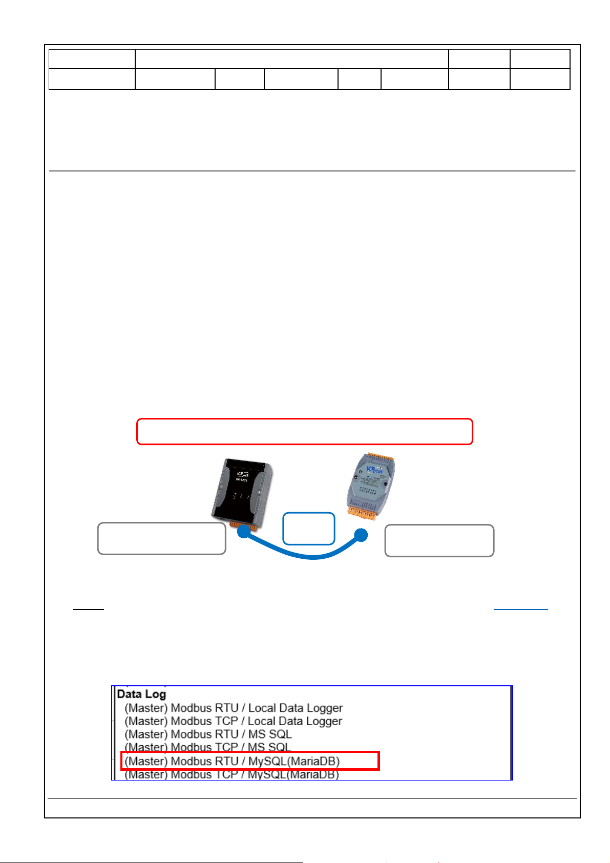
Modbus RTU / Remote Database MySQL(MariaDB)
Note: The hardware/network connection methods please see the UA Manual Chapter 2.
When UA series controller connects the Modbus RTU module (via RS-485/232, as the picture), user can
choose the item [Modbus RTU / MySQL(MariaDB] of the “Data Log” in the Function Wizard.
COM Port:
RS-485/RS-232
Modbus
RTU / ASCII
Module
RS-485: ttyO2, ttyO5
RS-232: ttyO4
Modbus RTU / MySQL(MariaDB) Remote Database
RS-485
RS-232
UA Series
Page 2
Classification
UA-Series English Function Wizard FAQ-dbl-05
Author
Eva Li
Version
1.0.0
Date
2021, 04
Page
2 / 17
ICP DAS Co., Ltd. Technical Document
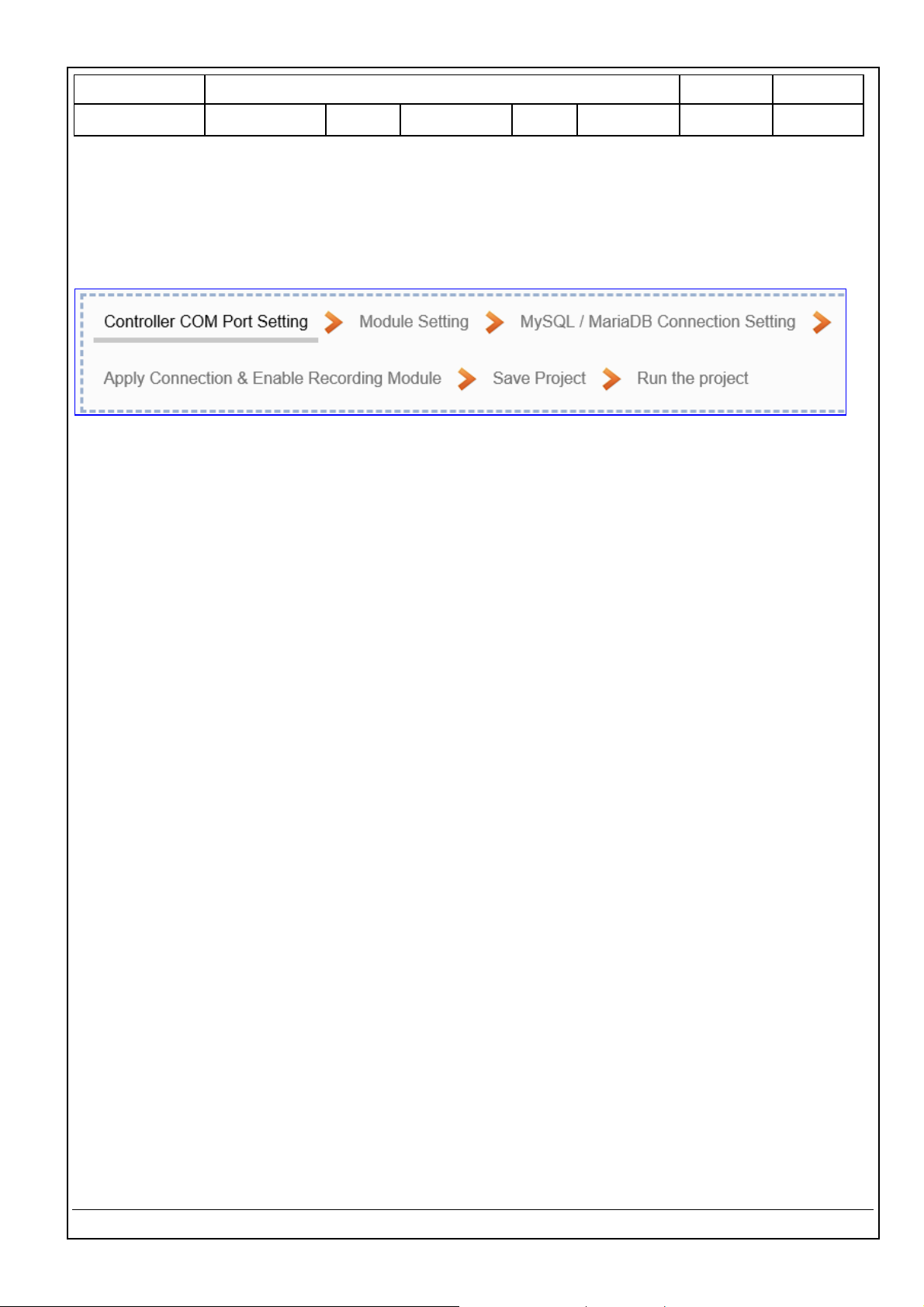
[Step Box]:
The Step Box of the [Modbus RTU / MySQL(MariaDB] has 6 steps. When enabling the Step Box, it auto
enters the first step setting page (The step with a bold underline means it is the current step.). The user
just needs to follow the “Step Box” step-by-step and then can complete the project quickly and rightly.
This example: UA-5231M-4GE via ttyO2 port to connect the device M-7026.
Page 3
Classification
UA-Series English Function Wizard FAQ-dbl-05
Author
Eva Li
Version
1.0.0
Date
2021, 04
Page
3 / 17
ICP DAS Co., Ltd. Technical Document
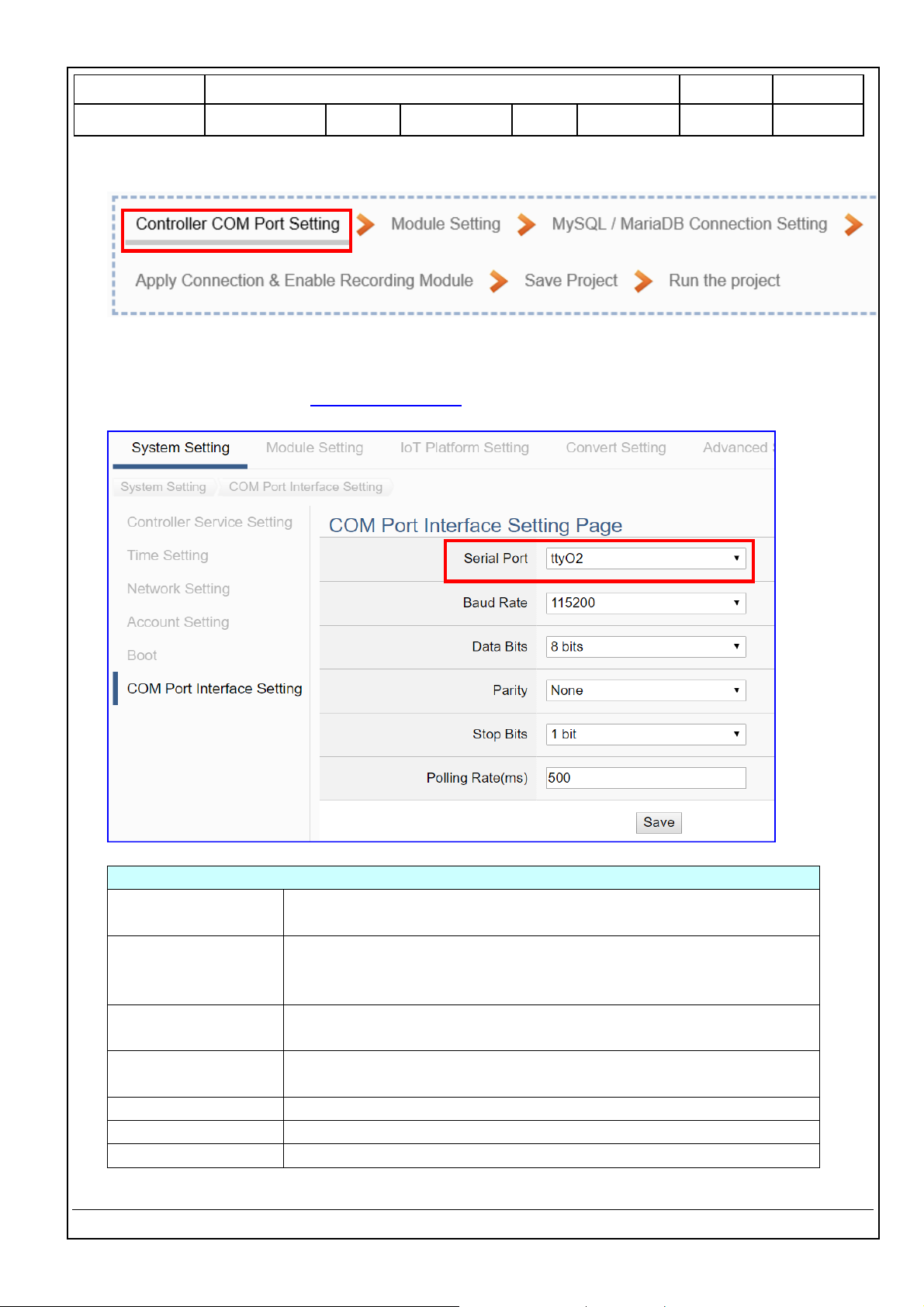
Step 1. Controller COM Port Setting
This page allows display and set the COM port interface of the controller for the RS-232/RS-485
serial communication. The user can find the default communication values of our I/O modules from
the module CD, manual or I/O Module website.
COM Port Interface Setting Page
Serial Port
Choose the serial port of UA controller that links with the I/O
module. ttyO2: RS-485 ; ttyO4: RS-232 ; ttyO5: RS-485
Baud Rate
Choose a baud rate to communicate with the module: 1200, 2400,
4800, 9600, 19200, 38400, 57600 and 115200. The UA controller
and the I/O module need have the same baud rate.
Data Bits
The number of bits used to represent one byte of data: 7 bits or 8
bits. Default: 8 Bits.
Parity
Choose one way for the parity checking.
Options: None, Even, and Odd. Default: None.
Stop Bits
Choose the number of stop bit: 1 bit or 2 bits. Default: 1.
Polling Rate(ms)
Set a time interval for the command. Default: 500 ms
Save
Click [Save] button could save the settings of this page.
Page 4
Classification
UA-Series English Function Wizard FAQ-dbl-05
Author
Eva Li
Version
1.0.0
Date
2021, 04
Page
4 / 17
ICP DAS Co., Ltd. Technical Document
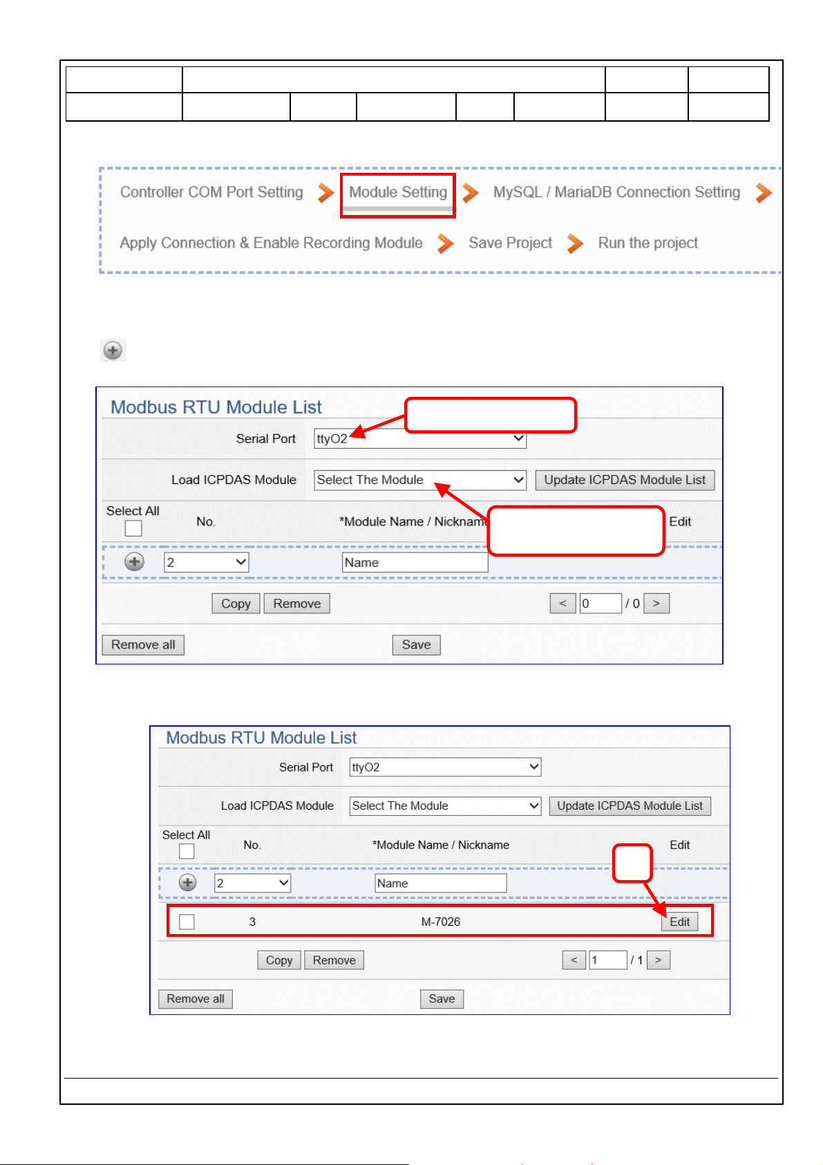
Step 2. Module Setting
It auto-enter the first step, Step 2 [Module Setting] of the UI setting.
This page is for setting the communication values with the connected modules. First check the port
that connected with the module, and each module can give a name (Default name: Name). Click
[ ] button could add a new module, and then click [Edit] button to configure the module content
and the Modbus mapping table.
The module (Ex: M-7026) is as below, and then click [Edit] button to enter the “Module Content
Setting” page.
If set up a wrong module, user can click the box in the left side of the module number and click the
[Remove] button to delete the module.
3
2. Select the module,
Ex: M-7026
1. Select the port
Page 5
Classification
UA-Series English Function Wizard FAQ-dbl-05
Author
Eva Li
Version
1.0.0
Date
2021, 04
Page
5 / 17
ICP DAS Co., Ltd. Technical Document
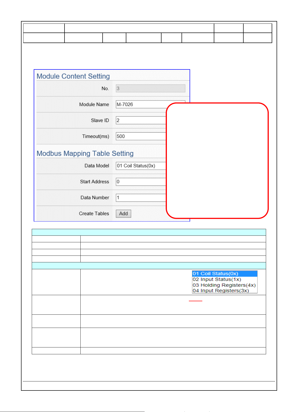
[Module Content Setting] page can set up the module and the Modbus mapping table:
Module Content Setting
No.
The module number in the module list (Not editable here)
Module Name
Give a name, e.g. model number or name. Default: Name.
Slave ID
Set the module Slave ID of the UA. (Range: 1 ~ 247)
Timeout
Set the timeout value for the module. Default: 500 ms
Modbus Mapping Table Setting
Data Model
System provides 4 Modbus data models
“01” ~ “04” for mapping to address of
DO, DI, AO and AI. (ex. 01: DO channels,
02: DI, 03: AO, 04: AI)
Start Address
The start address of the Modbus command. Note: the Start Address of UA
is bass on 0, even if some modules are bass on 1, here it needs to follow UA
to set bass on 0.
Data Number
The number of the Modbus address. Need to give enough number for the
DO, DI, AO, AI channels of the module. Default: 1.
Type
This item only when the data model is 03 or 04. Choose the suitable data
type: 16-bit Short, 16-bit Unsigned Short, 32-bit Long, 32-bit Unsigned
Long, 32-bit Float, 64-bit Double.
Create Tables
Click [Add] button, it will add a table in the Modbus mapping table.
Example: M-7026
For ICP DAS module, system will auto
setup the Modbus Mapping Table; if
not, user needs to check the Modbus
address or I/O number from the
module user manual.
[Slave ID] 2 (by user’s real case)
[ Modbus Mapping Table Setting ]
Data Model: 04 Input Registers(3x)
Start Address: 0
Data Number: 6
Type: 16-bit Short
Click [ Add ]
Page 6
Classification
UA-Series English Function Wizard FAQ-dbl-05
Author
Eva Li
Version
1.0.0
Date
2021, 04
Page
6 / 17
ICP DAS Co., Ltd. Technical Document
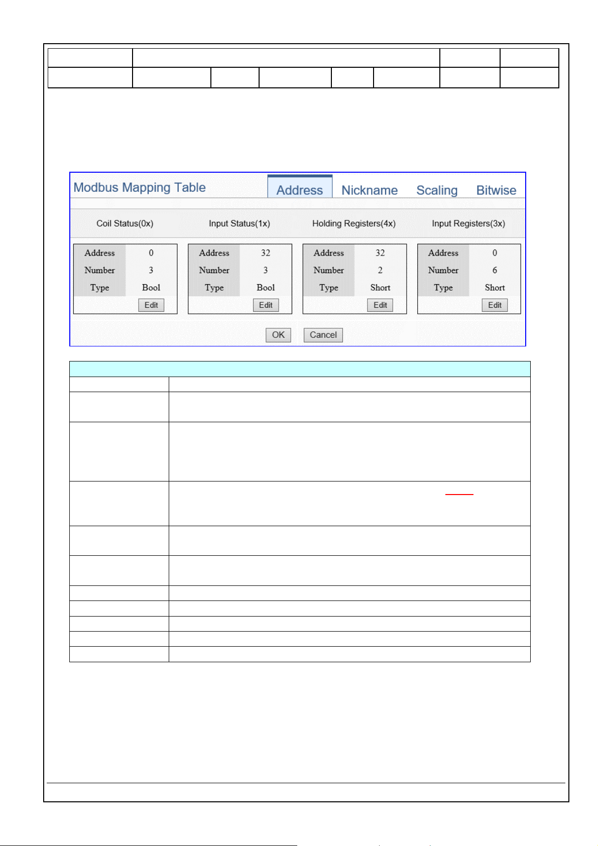
The finished Modbus Mapping Table as below is in order of mapping DO, DI, AO & AI.
Address:
Display and edit the Modbus Mapping Table.
Modbus Mapping Table – Address Setting
Address Setting
The “Address Setting” page of the Modbus Mapping Table
Nickname Setting
Click can switch to the The “Nickname Setting” page of the Modbus
Mapping Table. (Next page)
Modbus Mapping
Table
Coil Status(0x): Mapping to DO Modbus address
Input Status(1x): Mapping to DI Modbus address
Holding Registers(4x): Mapping to AO Modbus address
Input Registers(3x): Mapping to AI Modbus address
Address
The start address of the Modbus command. Default: 0. Note: the Start
Address of UA is bass on 0, even if some modules are bass on 1, here it
needs to follow UA to set bass on 0.
Number
The number of the Modbus address. Need to give enough number for
the DO, DI, AO, AI channels of the module. At least 1.
Type
DO/DI type: Bool (Boolean)
AO/AI type: depend on setting of [Modbus Mapping Table Setting]
Edit
Click to change the address and Number.
Delete
Click to delete this address table.
Save
Click to save and exit this table editing.
Cancel
Click to exit without saving and back to the module list page.
OK
Click to save this page settings and back to the module list page.
Page 7

Classification
UA-Series English Function Wizard FAQ-dbl-05
Author
Eva Li
Version
1.0.0
Date
2021, 04
Page
7 / 17
ICP DAS Co., Ltd. Technical Document
Nickname:
Setting the variable nickname and description.
Modbus Mapping Table – Nickname Setting
Modbus
Mapping Table
Coil Status(0x): Mapping to DO Modbus address
Input Status(1x): Mapping to DI Modbus address
Holding Registers(4x): Mapping to AO Modbus address
Input Registers(3x): Mapping to AI Modbus address
Table Display
Click [Show] to display all fields, click [Hide] to hide some fields.
Address
Modbus address. System auto arrange.
Variable name
The variable name of the mapping address. Default: Tag0 and auto
arrange the number. User can define the name.
Data Type
Display data type of the variable. (Not editable)
Swap
Check to swap the byte order (Lo-Hi/Hi-Lo) for 4-byte or 8-byte.
Description
Write a note for this variable.
OK
Click to save this page settings and back to the module list page.
Page 8
Classification
UA-Series English Function Wizard FAQ-dbl-05
Author
Eva Li
Version
1.0.0
Date
2021, 04
Page
8 / 17
ICP DAS Co., Ltd. Technical Document
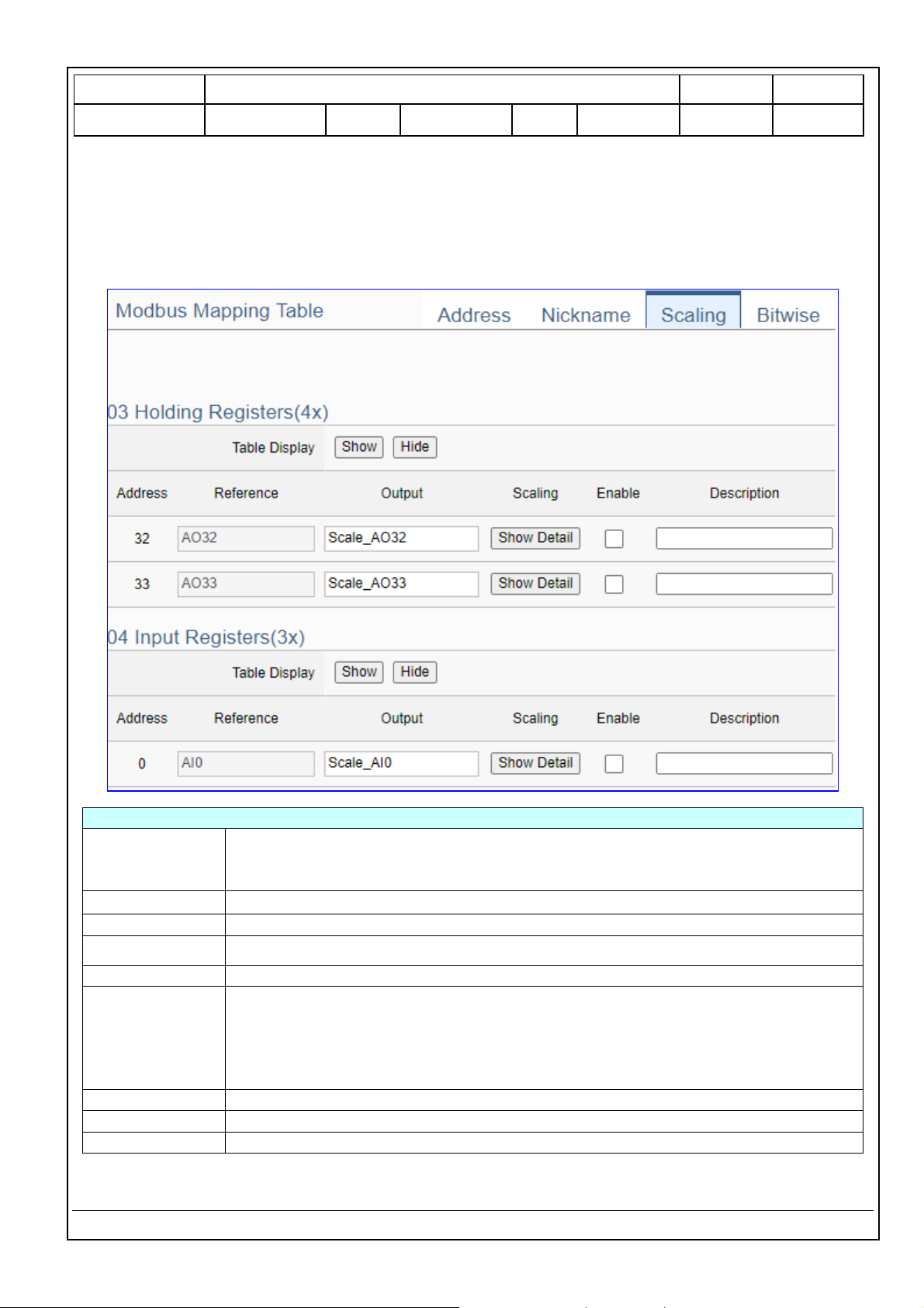
Scaling:
Scaling is only available in the AI/AO settings of Modbus RTU/TCP. When the variable value needs to be
scaled or converted before output, click the "Advanced Setting" button of the variable on the Scaling
page, input the Min./Max./Offset of the Reference/Output items, add a description, and check "Enable"
box, The Scaling conversion function will be activated.
Modbus Mapping Table – Scaling
Modbus
Mapping Table
Holding Registers(4x): Mapping to AO Modbus address
Input Registers(3x): Mapping to AI Modbus address
Scaling do not support 01 Coil Status(0x):DO & 02 Input Status(1x):DI
Table Display
Click [Show] to display all fields, click [Hide] to hide some fields.
Address
Modbus address. System auto arrange.
Reference
The I/O variable of the Modbus address.
Output
The scaling variable for scaling output. User can define the variable name.
Scaling
Click [Show Detail] to set up the Scaling parameters, and click [Hide Detail] to hide
the parameters.
Fill in the Min/Max range values of the source in the Reference column. Fill in the
Min/Max range values after scaling in the Output column. If needs offset, fill the
offset value in the Offset item. Remember check “Enable” box.
Enable
Check the box of the variable can enable just that variable for scaling.
Description
Write a note for this variable.
OK
Click to save this page settings and back to the module list page.
Page 9
Classification
UA-Series English Function Wizard FAQ-dbl-05
Author
Eva Li
Version
1.0.0
Date
2021, 04
Page
9 / 17
ICP DAS Co., Ltd. Technical Document
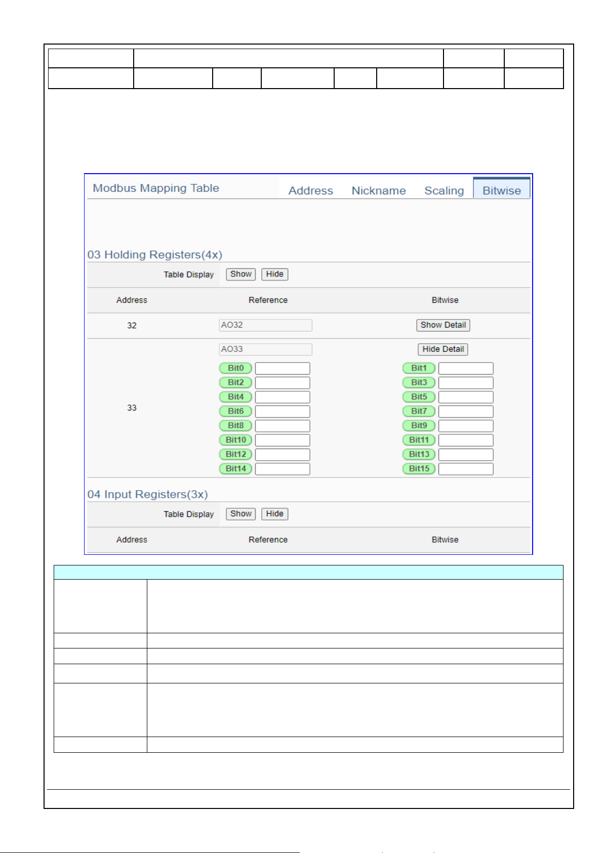
Bitwise:
Bitwise is only available in the AI/AO settings of Modbus RTU/TCP. When the data needed to take out
the value of the specified bit, fill in the variable name in the specified Bit# of the required address, and
the value of the bit can be output to the filled variable.
Modbus Mapping Table – Bitwise
Modbus
Mapping Table
Holding Registers(4x): Mapping to AO Modbus address
Input Registers(3x): Mapping to AI Modbus address
Bitwise do not support 01 Coil Status(0x):DO & 02 Input Status(1x):DI
Bitwise do not supports 32-bit Float & 64-bit Double data types.
Table Display
Click [Show] to display all fields, click [Hide] to hide some fields.
Address
Modbus address. System auto arrange.
Reference
The Bit# variables of the Modbus address.
Bitwise
Set up the variables for Bitwise. Click [Advanced Settings] to set up the Bitwise
parameters, and click [Hide] to hide the parameters.
Fill in the variable names to the Bit# that wanted to do the Bitwise. The value in
the fixed bit number will be assigned into the variable.
OK
Click to save this page settings and back to the module list page.
Page 10
Classification
UA-Series English Function Wizard FAQ-dbl-05
Author
Eva Li
Version
1.0.0
Date
2021, 04
Page
10 / 17
ICP DAS Co., Ltd. Technical Document
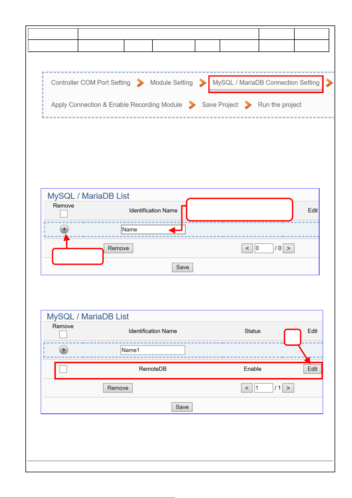
Step 3. MySQL/MariaDB Connection Setting
Click the next step, and enter the Step 3 [MySQL/MariaDB Connection Setting] of the UI setting.
This page is for setting the connecting remote database.
We select the “Modbus TCP / Remote Database” at the beginning, so this step will auto enter the
[Advanced Setting > Data Logger > MySQL / MariaDB] Setting. The “Step Box” will prevent the user
from selecting the wrong platform.
Add a database identification name (Ex: RemoteDB) as below, and then click [Edit] button to enter
the “MySQL / MariaDB Content Setting” page.
If set up a wrong module, user can click the box in the left side of the module number and click the
[Remove] button to delete the module.
1. Enter Identification Name
Ex: RemoteDB
2. Click +
3
Page 11
Classification
UA-Series English Function Wizard FAQ-dbl-05
Author
Eva Li
Version
1.0.0
Date
2021, 04
Page
11 / 17
ICP DAS Co., Ltd. Technical Document
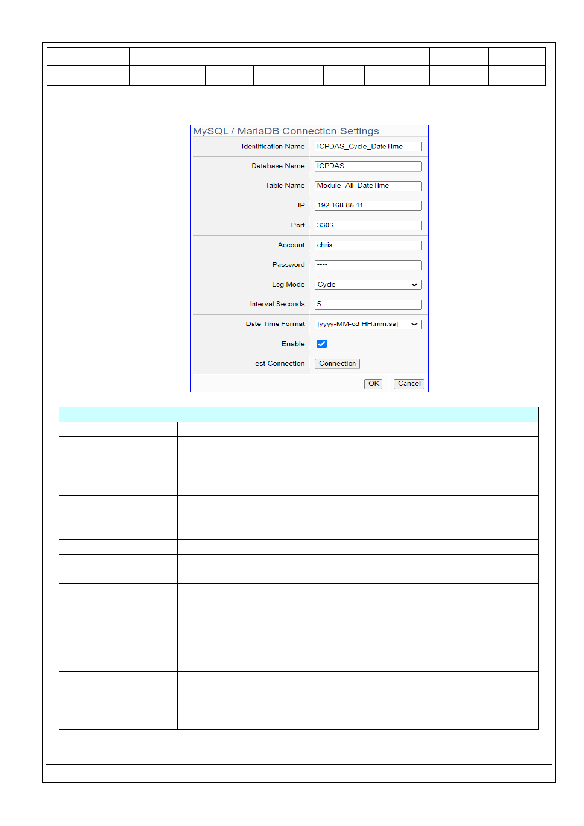
[MySQL / MariaDB Content Setting] can set up the database relational setting.
Advanced Setting > Data Logger > MySQL/MariaDB – Content Settings
Identification Name
User defined name to identify the database.
Database Name
The name of the remote database. If it does not exist, it will add a new
database with this name.
Table Name
The table name of the remote database. If it does not exist, it will add a
new table with this name.
IP
The Server IP and name of the remote database.
Port
The port to connect with database. Default: 3306 (for MySQL/MariaDB)
Account
The login name of the remote database.
Password
The login password of the remote database.
Log Mode
Cycle: Record one log data at the interval time set below.
Data Change: Only record when the data has changed.
Interval Seconds
Set up the interval time to save the I/O data to the remote database.
Unit: Second.
Date Time Format
Select to separate the date and time into two [Columns] or combine the
date and time in one [Column].
Enable
Check to enable the data logger to the remote database.
Default: check.
Test Connection
Click to test the connection to the remote database.
Result: Success or Failure.
OK / Cancel
Click “OK” to save the settings of this page.
Click “Cancel” to exit the setting page without saving.
Page 12

Classification
UA-Series English Function Wizard FAQ-dbl-05
Author
Eva Li
Version
1.0.0
Date
2021, 04
Page
12 / 17
ICP DAS Co., Ltd. Technical Document
Step 4. Apply Connection & Enable Recording Module
Click the next step, and enter the Step 4 [Apply Connection & Enable Recording Module] UI setting.
This step is to enable the Modbus RTU module and connection.
We select the “Modbus RTU /MySQL(MariaDB)” of “Data Log” at the beginning, so this step will auto
enter the [Logger Setting > MySQL/MariaDB > RTU Module (Master)] setting page. The “Step Box”
will prevent the user from selecting the wrong platform.
Here select and apply the Database name (Ex: RemoteDB), and enable the M-7026.
Logger Setting > MySQL/MariaDB > RTU Module (Master)
No.
The module number in the module list (Not editable here)
*Module Name /
Nickname
The module name set in the module list (Not editable here)
Edit
If user wants to enable some I/O channels for data logger, click [Edit]
of that module to enter the “Content Setting”. It is normal to set all
channels as enabled, and the function will not affect the
unconnected channels.
Database Name
Select and apply the recording remote database name.
All Enabled
Check [All Enabled] box to enable all modules in list for data logger.
Default: Uncheck. Check the “box” of each module can enable just
that module for data logger.
The page number of the module list: Current page / Total pages. Click
< or > to go to the previous or next page.
Save
Click to save the settings of this page.
Page 13

Classification
UA-Series English Function Wizard FAQ-dbl-05
Author
Eva Li
Version
1.0.0
Date
2021, 04
Page
13 / 17
ICP DAS Co., Ltd. Technical Document
Step 5. Save Project
The setting of this example is finished now. Click the next step [Save Project], the Step Box will show
an animation as below picture, that means the project is saving. When the animation vanished, the
project is saved completely.
Step 6. Run the Project
The project, after saving, needs to be executed. Click the next step [Run the Project]. This step can
also via the [System Setting > Controller Service Setting > Run Project] to Stop and Run the project.
When the words “Please wait” disappears, the new words “Success” appears, that means the UA
controller is running new project successfully. Then the Step Box will disappear automatically now,
and back to the first screen view of the Web UI.
The new project now completes the setting, uploading and running in the UA controller and can
process the new project communication. Users can see the I/O status from the menu [I/O Status].
For more about the Web UI settings, please refer to the UA Manual CH4 and CH5.
Page 14

Classification
UA-Series English Function Wizard FAQ-dbl-05
Author
Eva Li
Version
1.0.0
Date
2021, 04
Page
14 / 17
ICP DAS Co., Ltd. Technical Document
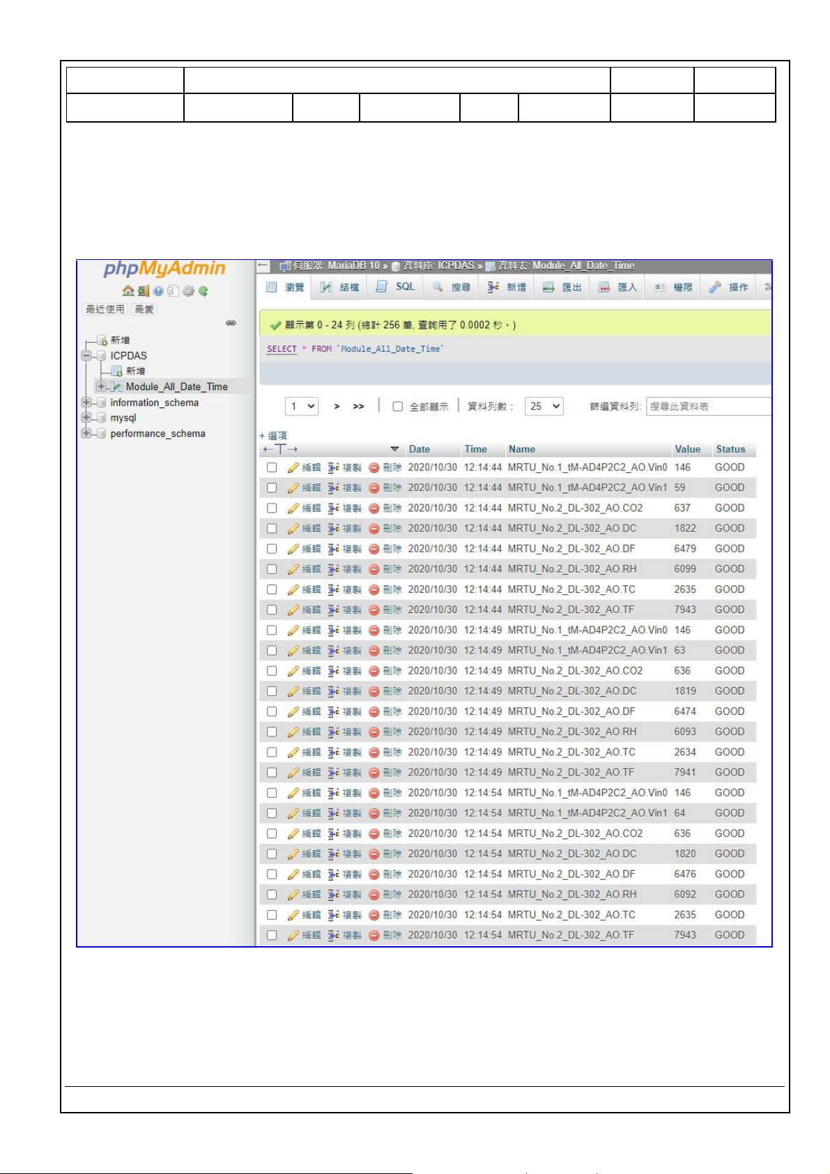
MySQL/MariaDB Remote Database Example Descriptions:
Each tag data and status are recorded in each separate row, the row is added down for each interval,
and the tag data is recorded in time sequence.
For database operation, please refer to FAQ-002 (MySQL) of the UA series FAQ list:
FAQ-002_How to save the UA collected data into SQL and then show trend chart in InduSoft? (Take
MySQL Installer 5.7.31 as an example)
The connection screen view of the MySQL Remote Database.
1. MySQL database screen view: Date/Time column separated (reference)
Page 15

Classification
UA-Series English Function Wizard FAQ-dbl-05
Author
Eva Li
Version
1.0.0
Date
2021, 04
Page
15 / 17
ICP DAS Co., Ltd. Technical Document
2. MySQL database screen view: Date/Time column combined (reference)
Page 16
Classification
UA-Series English Function Wizard FAQ-dbl-05
Author
Eva Li
Version
1.0.0
Date
2021, 04
Page
16 / 17
ICP DAS Co., Ltd. Technical Document
The connection screen view of the MariaDB Remote Database.
1. MariaDB database screen view: Date/Time column separated (reference)
Page 17

Classification
UA-Series English Function Wizard FAQ-dbl-05
Author
Eva Li
Version
1.0.0
Date
2021, 04
Page
17 / 17
ICP DAS Co., Ltd. Technical Document
2. MariaDB database screen view: Date/Time column combined (reference)
 Loading...