

Page 1
1j
TM
ESC Utility User Manual
Industrial Redundant Ring Switch
Version 1.0
This document applied to models of
RS-405/405F, RSM-405/405F
Mar 28, 2007
Please print in double side
TDRS4050601
Page 2

Page 3

Industrial Redundant Ring Switch – RS Series User Manual
i
Date
Author
Version
Description
Mar 28th, 2007
May Chang
1.0
First draft
Document Control
TDRS4050601
Page 4

Industrial Redundant Ring Switch – RS Series User Manual
ii
Copyright & Trademarks
Al l r ights reser ved . No part of t his publ i cat ion m ay b e
rep r od uced, s t ored in a ret ri eval sy st em, o r t ransm itt ed in
any f or m or by any m eans , w he ther e le ct ro ni c, me ch ani cal,
phot o c o py i ng, rec o rd ing o r ot herw i se, w i thout t he prior
wri t ten pe rm i ss ion of t he pub l is her .
The nam es used f or id ent ifi c at io n o nl y may be re g ist ered
tr ad em ark s of t he ir resp e ct iv e com pa ni es .
Cop y right© IC P D AS Co ., L td ., A ll R ig ht s Res er v ed .
TDRS4050601
Page 5
Industrial Redundant Ring Switch – RS Series User Manual
iii
Disclaimer
Limited Warranty
Al l p rodu ct s man u factu red by ICP DA S are w arr ant ed a gain s t
de f ect ive m at eria ls for a per i od of on e year from t he dat e o f
de l iv ery t o th e ori g in al p u rch a ser. During t his per iod, if a
cus tom er is una b le t o res olve a p rodu ct prob l em with I CP D A S
Tec h nica l Sup p ort , a Ret urn M at er ial A ut h or iz at ion ( RM A ) will
be is sued. If t he p rod uct is n ot u nd er warr anty , th e custom e r
ma y have I CP D A S r ep air t he unit o n a fee b asis or retu r n it .
Thi s war ra nty is vo id ed if t he cust omer u ses t he p rod uc t in
an un au thori zed or i mprop er wa y , or i n an e n v ironm e nt for
whi c h it w a s not d esi gn ed .
Standards
Warning
Safety
The Ring Swit c h m eet s t he f ollow i ng st and ard s:
EM C imm un it y - I EC 61326 -1 , IE EE C37 .9 0
EM I em i ss io ns - F CC part 1 5, ICES 00 3, EN550 22 ; Clas s B
Ele c tri c al s af ety - U L 50 8, C SA C22/1 4; E N 61 010 -1 ( IEC 10 10 )
ICP DAS ass um e no liab il it y for d am ag es cons eq ue nt t o t he
use o f th is prod uc t . ICP D A S re s er v es t he ri ght t o chan ge thi s
ma n ua l at any t ime w i thout n o tic e. T he inf orm at ion f ur n ished
by ICP DAS is be li ev ed t o b e a c curat e and re li ab le . However,
no re sponsi bi li ty is ass um e d by I CP D A S f o r it s us e, no r for
any infr in gem ent s of pat ents or ot he r rig ht s of t hird pa rt ies
res ul ting f rom its us e.
Ins tall t he R ea l Tim e Ri ng S w it ch i n acc o rd an ce wi th l oc al an d
nat iona l elect ri cal c od es .
Lig h tni ng D an ge r: Do no t work o n equi pm en t duri ng pe ri od s of
ligh tnin g act ivity .
Do not c on nect a t elep h on e li ne in t o one of t he Et hern et R J4 5
con n ect ors .
TDRS4050601
Page 6

Industrial Redundant Ring Switch – RS Series User Manual
iv
Contents
Document Control ......................................................................................... i
Copyright & Trademarks ............................................................................... ii
Disclaimer...................................................................................................... iii
Limited Warranty .................................................................................................. iii
Standards ............................................................................................................. iii
Warning ................................................................................................................ iii
Safety ................................................................................................................... iii
Contents ........................................................................................................ iv
Acronyms ...................................................................................................... a
Introduction.................................................................................................... d
Key Features ........................................................................................................ e
Intended Hardware Product .................................................................................. e
Installation ..................................................................................................... f
Before Installing .................................................................................................... g
Downloading & Updating ................................................................................ g
Operating System Requirement ................................................................ ...... g
Installation ................................ ................................ ............................................ h
Initial Setup .................................................................................................... h
License agreement ...........................................................................................i
Customer Information .......................................................................................j
Installation Folder ............................................................................................k
Shortcut Folder .................................................................................................l
Ready to install the program .......................................................................... m
Installing the program ..................................................................................... n
Complete Installation ...................................................................................... o
Configuration ................................................................................................. p
Start the Program ................................................................................................. q
Basic Interface....................................................................................................... r
Configuration Page Overview .......................................................................... r
Network Status ................................ ................................ ................................s
Time Status ..................................................................................................... t
DIP Switch Status ............................................................................................ t
Relay Setting .................................................................................................. u
Program Options .............................................................................................v
Upgrade Firmware ................................ ................................ ...........................y
Default.............................................................................................................y
Restart ............................................................................................................z
Advanced Mode ..............................................................................................z
Open Log File ..................................................................................................z
About Utility .................................................................................................. aa
Exit Program ................................................................................................ aa
System Status .............................................................................................. bb
Hardware Status Page Overview ................................................................... cc
DIP Switch(SW1) configuration ..................................................................... dd
Rotary Switch (SW2) configuration................................................................ ee
Power 1 & Power 2 Status .............................................................................. ff
Advanced Interface ................................................................................................ ii
TDRS4050601
Page 7

Industrial Redundant Ring Switch – RS Series User Manual
v
Configuration Page Overview .......................................................................... ii
Network Status ................................ ................................ ................................ jj
Time Status ................................................................................................... kk
DIP Switch Status .......................................................................................... kk
Relay Setting ................................................................................................... ll
Program Options .........................................................................................mm
Upgrade Firmware ................................ ................................ ........................ pp
Default.......................................................................................................... pp
Restart ......................................................................................................... qq
Advanced Mode ........................................................................................... qq
Open Log File ............................................................................................... qq
About Utility .................................................................................................... rr
Exit Program .................................................................................................. rr
System Status ............................................................................................... ss
Link Status Page overview .............................................................................. tt
Show Help ..................................................................................................... vv
Link Lose Alarm Mask Status......................................................................... vv
Communication Status Page overview ......................................................... ww
Show Help ..................................................................................................... xx
Communication Lose Alarm Mask Status ....................................................... xx
Hardware Status Page overview ..................................................................aaa
DIP Switch(SW1) configuration ....................................................................bbb
Rotary Switch (SW2) configuration............................................................... ccc
Power 1 & Power 2 Status ...........................................................................ddd
Alarm Output and Event Log ........................................................................ddd
Event Type .................................................................................................... eee
Event Type 1:Power 1 Error ........................................................................... fff
Event Type 2: Power 2 Error .......................................................................... fff
Event Type 3: RS-232/RS-485 Connection Error ........................................... fff
Event Type 4: Link Error ................................................................................ fff
Event Type 5: Firmware Error ........................................................................ fff
Event Type 6: Power or RS-232/RS-485 Connection Error............................. fff
Event Type 7: This switch has been assigned as the master switch. .............. fff
Event Type 8 :Unknown Error ......................................................................ggg
Troubleshooting ............................................................................................ hhh
Event Type 1: Power 1 Error ........................................................................... iii
Event Type 2: Power 2 Error ........................................................................... iii
Event Type 3: RS-232/RS-485 Connection Error ............................................ iii
Event Type 4: Link Error ................................................................................. iii
Event Type 5: Firmware Error ......................................................................... jjj
Event Type 6: Power or RS-232/RS-485 Connection Error.............................. jjj
Service Information ....................................................................................... kkk
On-line support ................................ ................................ .................................. kkk
Contact Worldwide ............................................................................................ kkk
TDRS4050601
Page 8

Industrial Redundant Ring Switch – RS Series User Manual
a
ATM
Acronym for Asynchronous Transfer Mode, a high performance
networking technology based on the switching of fixed length, 53 byte
cells. ATM switching supports the switching of voice, video, and data;
also supports isochronous communication.
BPV
Acronym for Bi-Polar Violation.
B-ISDN
Broadband ISDN. A network standard from the CCITT and ANSI
committee. It supports voice, data and video in the same network.
CCITT
Acronym for Consultative Committee, International Telephone and
Telegraph. An international standards body responsible for setting
international communications standards that allow interoperability
among telephony and data communications equipment.
CD (DCD)
Acronym for Carrier Detect (Detect Carrier Detect).
CDDI
The use of unshielded or shielded twisted pair cable to transmit the
FDDI signal.
CO
Acronym for Central Office. The local telephone company switch that
terminates subscribers' lines for switching and connecting to the
public network.
CSMA/CD
Acronym for Carrier Sense Multiple Access with Collision Detection.
Access protocol for Ethernet.
CSU
Acronym for Channel Service Unit, a device furnished as an integral
part of a digital access line where a user wishes to supply the bipolar
signals. It provides the network with protection against user side
electrical anomalies such as surges, and provides the user with
network clocking.
CTS
Acronym for Clear To Send.
DCE
Acronym for Data Communication Equipment, aka. Data CircuitTerminating Equipment.
DCR
Acronym for Data Communication Ready.
DS1
Digital Signal, Level 1 is the North American data rate used for T1
carriers. It operates at 1.544Mbps and supports 24 phone lines.
DS2
Digital Signal, Level 2 is the North American data rate used for T2
carriers. It operates at 6.312 Mbps and supports four T1 lines or 96
phone calls
DS3
Digital signal, Level 3 is the North American data rate used for T3
carriers. It operates at 44.736 Mbps and supports 28 T1 lines.
DSU
Acronym for Data Service Unit, a DCE used with digital
communications circuits to provide digital data services interface.
Located on the users premises, the DSU interfaces directly with the
DTE, and provides loop equalization, remote and local test
Acronyms
TDRS4050601
Page 9

Industrial Redundant Ring Switch – RS Series User Manual
b
capabilities, and the logic and timing necessary to provide a standard
EIA/TIA or CCITT interface. Converts signals between those used at
the DTE's serial interface and bipolar signals used on the digital
network. Also Network Terminal Unit (NTU).
DTE
Acronym for Data Terminating or Data Terminal Equipment.
DTR
Acronym for Data Terminal Ready.
E1
The European standard for high speed, point to point transmission
operating at 2.048 Mbps and defines 64 Kbps sub-channels.
EIA
Acronym for Electronic Industries Association. EIA, a standards body,
has a set of standards which includes data communications and
interface standards among others.
EMI
Acronym for Electro-Magnetic Interference.
FEP
Stands for Front End Processor. It is an IBM communication controller
that routes traffic to and from cluster controllers.
FDDI
Acronym for Fiber Distributed Data Interface, is a shared medium, ring
topology LAN that operates at 100 Mbps. It is ANSI standard X3T9.5,
using fiber optic cable as the medium.
FPGA
Acronym for Field Programmable Gate Array.
LAN
A local area network is a group of PCs connected over a common
medium within a building.
MAC
Acronym for Medium Access Control. A designated hardware address
for each device on a LAN or MAN. This address is burnt into The
network interface card (NIC) by its manufacturer.
MAN
A metropolitan area network is a group of PCs connected over a
common medium within a campus environment or the same city.
NA
Acronym for Numerical Aperture.
OC1
Optical Carrier Signal Level 1 refers to SONET data transmission at
51.840Mbps.
OC3
Acronym for Optical Carrier 3, a transmission rate standard for fiber
optic telephony or data communications circuits. OC3 operates at 155
Mbps speed and is part of the SONET hierarchy.
OC12
Optical Carrier Signal Level 12 refers to SONET data transmission at
622.080Mbps.
OSI
(Open Data Interconnection Reference Model) - This is the
International Standards Organization (ISO) model of how data
communications systems can be interconnected. Communication is
partitioned into seven function layers. Each layer builds on the
services provided by those under it.
PBX
Acronym for Private Branch Exchange, is a small private version of a
phone company's larger central switching office.
TDRS4050601
Page 10

Industrial Redundant Ring Switch – RS Series User Manual
c
PCM
Acronym for Pulse-Coded Modulation, a means of converting analog
to digital form.
RING
Path or channel; usually electrical, where devices along the path
receive transmissions sequentially from one device to the next along
the ring.
RS-232
An interface used between DTE and DCE employing serial binary
data interchange, defined by EIA, aka. EIA-232. Similar to standard
V.24 of CCITT.
RS-422
Standard defined by EIA, aka. EIA-422. Deals with the electrical
characteristics of balanced voltage digital interface circuits. Similar to
standard V.11 of CCITT.
RS-423
Standard defined by EIA, aka. EIA 423. Deals with electrical
characteristics of unbalanced voltage digital interface circuits. Similar
to standard V.10 of CCITT.
RS-449
Standard defined by EIA, aka. EIA-449. Deals with general-purpose
37- and 9-position interface for data terminal equipment and data
circuit-terminating equipment employing serial binary data
interchange.
RS-485
Standard defined by EIA, aka. EIA-485. Standard for electrical
characteristics of generators and receivers for use in balanced
multipoint systems.
RTS
Acronym for Request To Send.
SCADA
Acronym for Supervisory Control and Data Acquisition.
SNMP
Acronym for Simple Network Management Protocol. A standard
management protocol used to provide a common means of managing
network devices.
SONET
Acronym for Synchronous Optical NETwork, is a hierarchical standard
for a high speed (45 Mbps to 2.4 Gbps) transport network.
T1
Transmission rate standard for telephony or data communications
circuits. T1 operates at 1.544 Mbps speed. Usually this circuit is
subdivided into many 64 Kb channels.
TCP/IP
Acronym for Transmission Control Protocol/Internet Protocol.
WAN
Acronym for Wide Area Network, a computer network interconnected
over distances beyond a city or metropolitan area.
802.3
Commonly referred to as Ethernet. It is a local area network protocol
that operates at 10Mbps.
802.5
Commonly referred to as Token Ring. Operates at either 4 or 16Mbps.
TDRS4050601
Page 11

Industrial Redundant Ring Switch – RS Series User Manual
d
Key Features
Intended Hardware
Product
Introduction
Welcome to ICP DAS Industrial Redundant Ring Switch - RS
Series, one of the world’s best Industrial Ethernet Switch designed
for connecting Ethernet-enabled devices in industrial field
applications. This manual is for the ICP DAS RS-405 Series, Ethernet
network switch.
Overview
The Ethernet Switch Configuration Utility software is a graphical user
interface program that allows you to configure settings and monitor
status for RS-405 series. The easy-to-use GUI design helps reduce
learning curve and enables technicians to perform tasks intuitively
without full IT knowledge. With this specifically designed software,
just a few clicks away, you are able to take advantage of all the
features and resources available from this advanced ring switch.
This manual details how to install and configure various settings in
this ESC Utility software. To take full advantage of all the features
and resources available from the switch, please follow the steps to
initiate installation and configuration.
.
TDRS4050601
Page 12

Industrial Redundant Ring Switch – RS Series User Manual
e
Key Features
Multi-language interface supported (English/Simplified Chinese/ Traditional Chinese )
Easy-to-use Graphic user interface (GUI)
Real-Time access and configuration (via RS232 & RS485)
Real-Time event log monitoring and notification
Intended Hardware Product
This manual applies to ESC Utility Ver. 1.00 in the following products:
• RS-405: 5-Port Redundant Ring Switch
• RS-405F: 3-Port 10/100 Base-T with 2-Port 100 Base-FX Fiber Redundant Ring
Switch
• RSM-405: 5-Port Redundant Ring Switch with metal case
• RSM-405F: 3-Port 10/100 Base-T with 2-Port 100 Base-FX Fiber Redundant Ring
Switch with metal case
TDRS4050601
Page 13

Industrial Redundant Ring Switch – RS Series User Manual
f
Before Installing
Installation
Installation
Overview
This chapter provides general information you need to know before
you start installing ESC Utility.
TDRS4050601
Page 14

Industrial Redundant Ring Switch – RS Series User Manual
g
Before Installing
Downloading & Updating
To get the latest version of this user manual and to download/update the latest firmware,
please go to :
http://www.icpdas.com/
Operating System Requirement
Windows 95 / 98 / ME / 2000 / NT / XP
TDRS4050601
Page 15
Industrial Redundant Ring Switch – RS Series User Manual
h
Installation
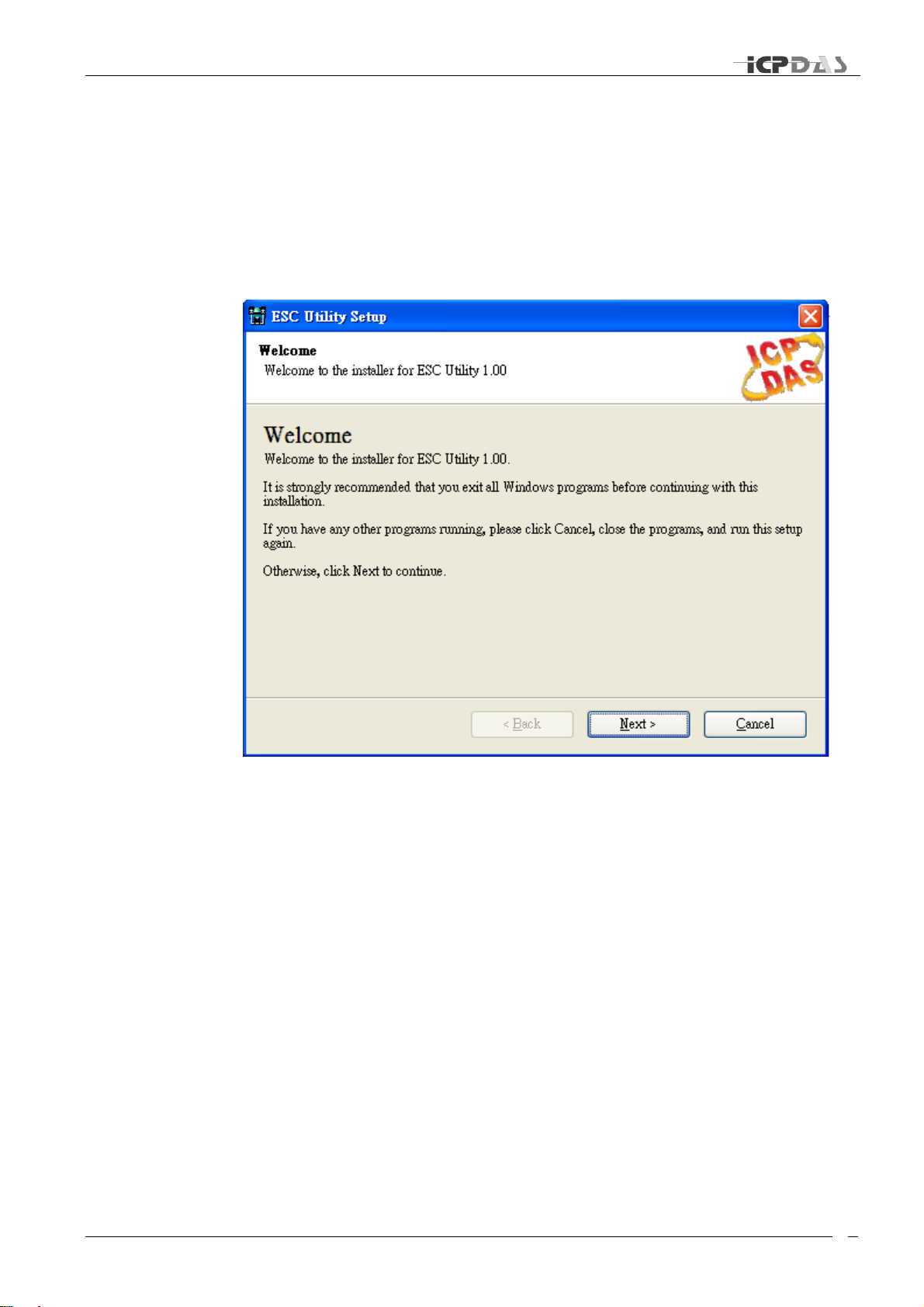
Once you download and decompress the file, double click ESC Utility 1.00.exe to start
the Installation Wizard.
Initial Setup
The Installation Wizard will guide you through the installation process:
It is strongly recommended that you exit all Windows programs before continuing with this
installation.
If you have any other programs running, please click Cancel, close the programs, and run
this setup again.
Otherwise, click Next to continue.
TDRS4050601
Page 16
Industrial Redundant Ring Switch – RS Series User Manual
i
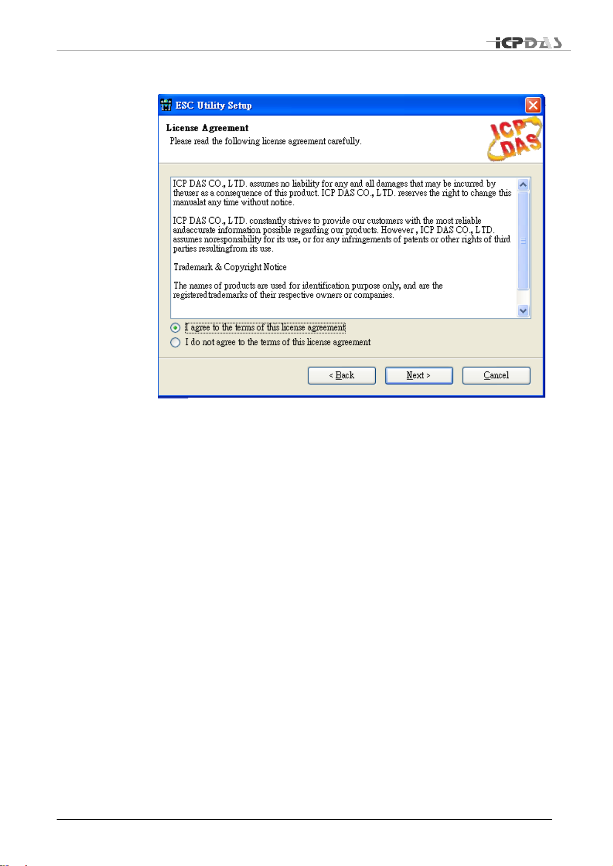
License agreement
Please read the license agreement carefully, click “I accept the terms in the license
agreement” and then click “Next” to continue.
TDRS4050601
Page 17
Industrial Redundant Ring Switch – RS Series User Manual
j
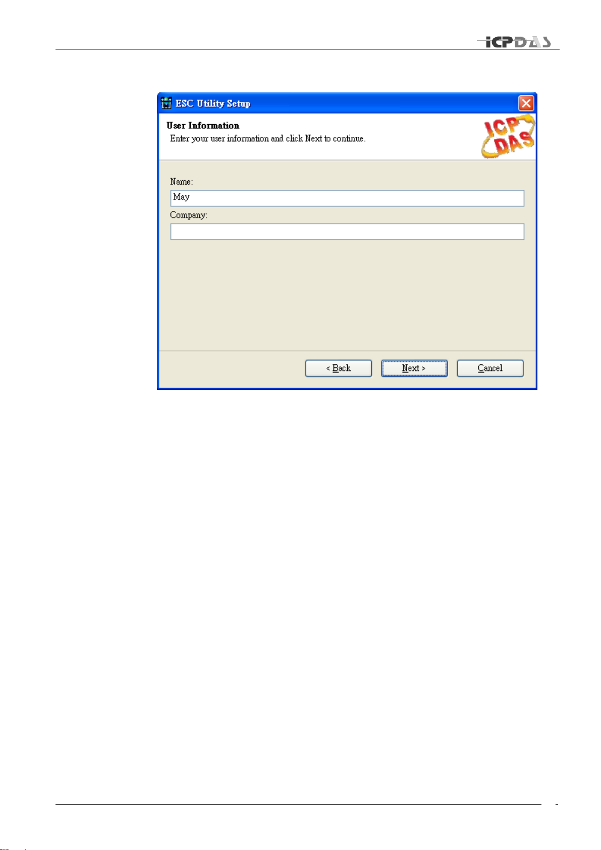
Customer Information
Enter your name and company name.
Then click “Next” to continue.
TDRS4050601
Page 18
Industrial Redundant Ring Switch – RS Series User Manual
k
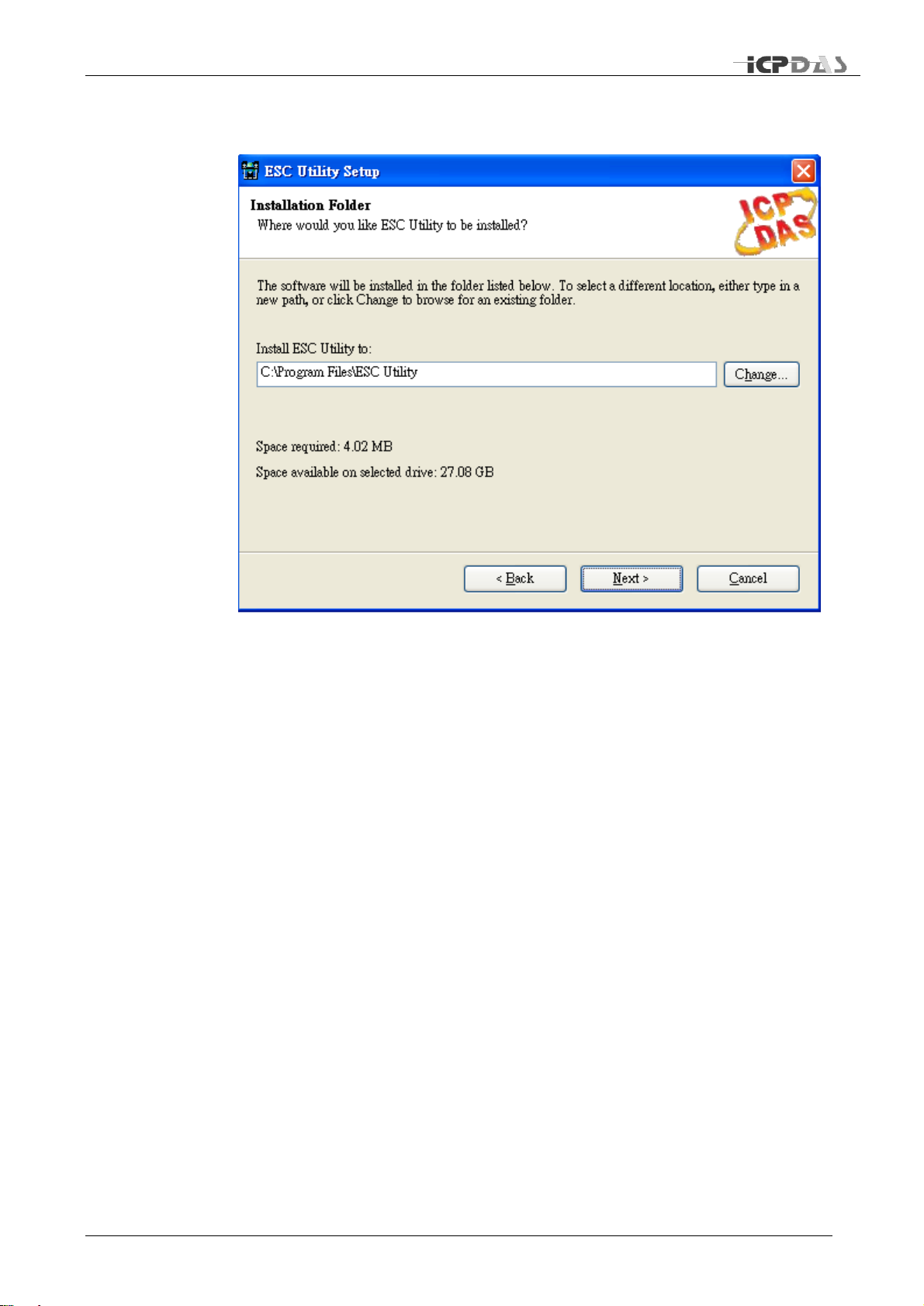
Installation Folder
The software will be installed in the folder listed. To select a different location, either type
in a new path, or click change to browse for an existing folder.
Then click “Next” to continue.
TDRS4050601
Page 19
Industrial Redundant Ring Switch – RS Series User Manual
l
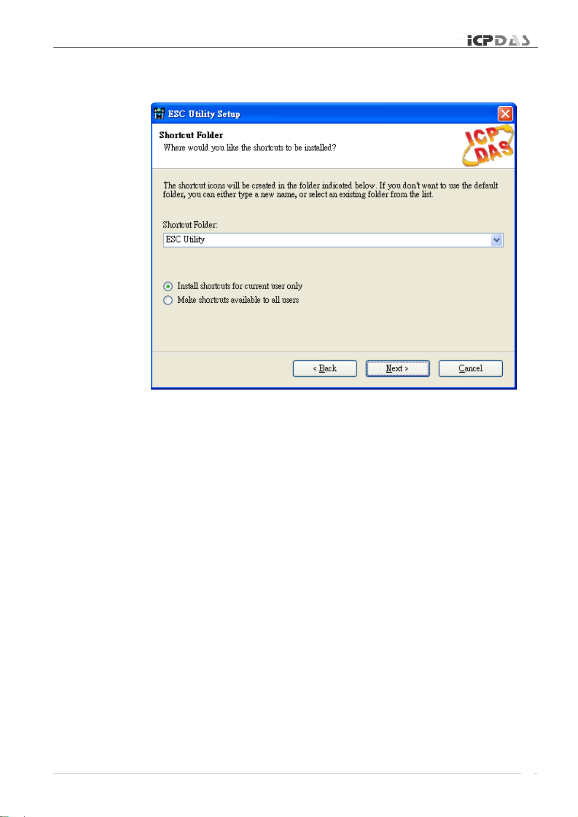
Shortcut Folder
The shortcut icons will be created in the folder indicated below. If you don’t want to use
the default folder, you can either type a new name, or select an existing folder from the
list.
If you want to install shortcuts for current user only, click “Install shortcuts for current user
only”.
If you want to install shortcuts for all users, click “Make shortcuts available to all users”.
Then click “Next” to continue.
TDRS4050601
Page 20
Industrial Redundant Ring Switch – RS Series User Manual
m
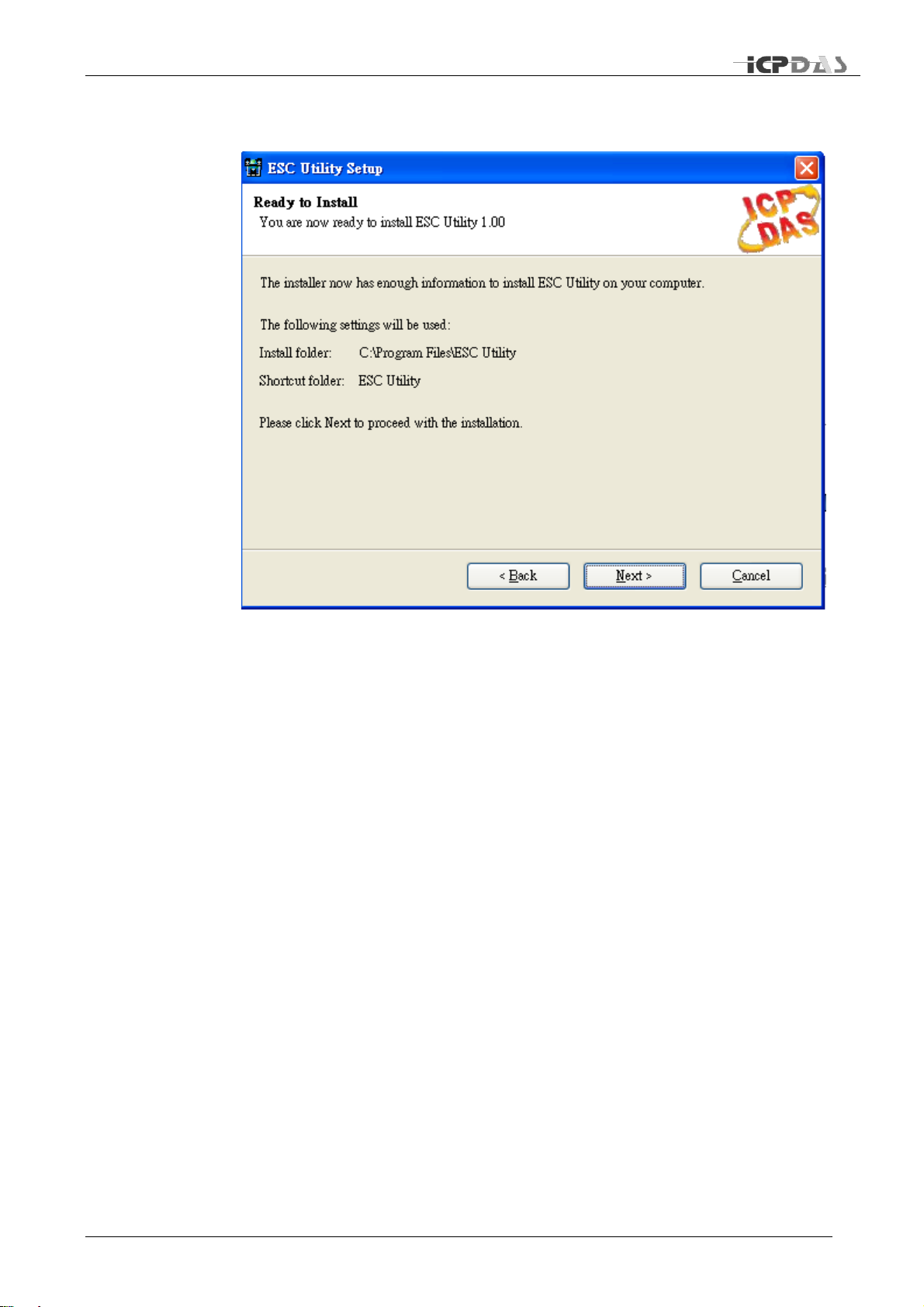
Ready to install the program
Click “Next” to begin the installation. If you want to review or change any of your
installation settings, click “Back”. Click “Cancel” will exit the wizard and quit installation.
TDRS4050601
Page 21
Industrial Redundant Ring Switch – RS Series User Manual
n
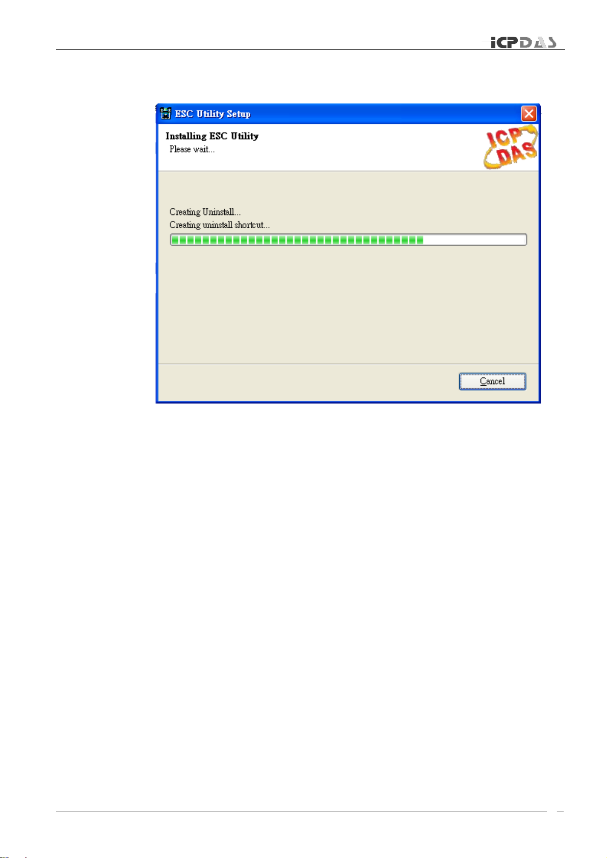
Installing the program
It may take a few seconds to install this program.
TDRS4050601
Page 22

Industrial Redundant Ring Switch – RS Series User Manual
o
Complete Installation
To close this wizard, click Finish
TDRS4050601
Page 23

Industrial Redundant Ring Switch – RS Series User Manual
p
Start the Program
Basic Interface
Advanced Interface
Configuration
Overview
This chapter provides information about how to configure an existing
device by ESC Utility.
TDRS4050601
Page 24

Industrial Redundant Ring Switch – RS Series User Manual
q
Start the Program
To start the program, please do the following steps:
1. From the window desktop, click on Start -> Programs ->ESC Utility -> ESC Utility Ver
1.00 to run the program (or the route you previously set up for this program).
I
2. Input the com port: 1 for com1, 2 for com2, etc.
3. Please select the Interface of you preference: Basic interface is designed for beginners
and Advanced interface is designed for advanced users.
4. Please select the language of you preference: click on English for English Interface, or
click on Chinese (Simplified or Traditional) for Chinese interface*.
5. Click on “connect” to make a connection to the serial port.
TDRS4050601
Page 25

Industrial Redundant Ring Switch – RS Series User Manual
r
Basic Interface
Click on tags to go to the following pages: Hardware Status and Configuration pages.
Configuration Page Overview
Configuration page displays current settings. From here, you can monitor and modify
current settings.
TDRS4050601
Page 26

Industrial Redundant Ring Switch – RS Series User Manual
s
Network Status
Upper left section displays Network Status. You can monitor and configure current
Network settings in this section: TCP/IP address, MASK IP, GATEWAY IP, Ethernet
Address, Modbus Net ID, and Monitor Timer Interval. To make a modification, please
type new values in the fields that you would like to make a change of, and then click on
the button. Please note: the button will appear ( gray out) before you
input new values.
The first field in this section: TCP/IP displays current TCP/IP address. Its default value is:
192.168.255.1. To assign an IP address for TCP/IP, please input IP address in the form:
“ip1.ip2.ip3.ip4”(in the range 0.0.0.0-223.255.255.255).
The second field in this section: MASK IP display current MASK IP address. Its default
value is: 255.255.255.0. To assign a mask address for TCP/IP, please input mask
address in the form of “m1.m2.m3.m4”(each field contains a value in the range 0 – 255).
The third field in this section: GATEWAY IP display current GATEWAY IP address. To
assign a gateway address for TCP/IP, please input gateway IP address in the form of
“ip1.ip2.ip3.ip4” (each field contains a value in the range 0 – 255). The default value is
255.255.255.255.
The fourth field in this section: Ethernet Address display current Ethernet MAC address.
The default value is a factory-set unique MAC address. To assign a Ethernet MAC
address, please input gateway IP address in the form of “e1:e2:e3:e4:e5:e6” (each field
contains a value in the range 0 – 255).
Note: Each RS is shipped from the factory with a unique MAC address. DO NOT change
this address unless you have a good reason to do so.
The fifth field in this section: Modbus Net ID display current Modbus Net ID. The default
value is set as 1. Please assign a unique number to each switch in the same ring.
The last field in this section is: Monitor Timer Interval. Please input an appropriate
monitoring time interval for your system. Its default value is 2000 ms (1000ms = 1 sec).
Maximum value is 60,000ms ( 60 sec).
TDRS4050601
Page 27

Industrial Redundant Ring Switch – RS Series User Manual
t
Time Status
Upper right section displays Time Status. You can monitor and configure current Time
setting interval in this section: Recovery Time(in the range 100-65535ms), Max Age
Time(in the range 6000-40000ms), Forward Delay(in the range 4000-30000ms), and
Hello Time (in the range 1000-10000ms). To make a modification, please type new
values in the fields that you would like to make a change of, and then click on the
button. Please note: the button will appear ( gray out) before you input new
values. To make the value you input effectively, please click on “Restart” button.
Note that the Switch Value indicates the value you configure and save on this Ring
Switch. However, only the Switch Value being set on Master Switch will be adapt as the
actual value (Operating Value) being applied to all switches in the same ring.
DIP Switch Status
This section shows current DIP Switch Status. Each jumper has two possible conditions:
on or off. Each position indicates one configuration state. To make a change of the
jumper state, please switch the jumpers on the Ring Switch directly and then click
“Restart” button to make the newly changed settings effective.
TDRS4050601
Page 28

Industrial Redundant Ring Switch – RS Series User Manual
u
Relay Setting
Relay Setting section allows you to monitor or configure current settings of Relay output.
There are three kinds of relay output that you can set up with: Link Lose, Communication
Lose, and System.
Link Lose relay output:
To set up the relay output for port(s), please check the square box in front of the port.
After you are done with your selections, please click button. When there is a link
loss occurs on the port(s) you check, relay output will be activated. A warning sign will
also be shown on Hardware Status page.
Note that Preview value is for you to easy preview the mask value when you are checking
the ports you’d like to set relay output for, this value will be effective only after you click
button.
Communication Lose relay output:
To set up the relay output for port 1, port 2, please switch SW1 jumper 6 to “on” position
and click “restart” button; for port 3, port 4, port 5, please switch SW1 jumper 5 to “on”
position and click “restart” button.
Check the square box in front of the port you’d like to set relay output for. After you are
done with your selections, please click button. When there is a communication loss
occurs on the port(s) you check, relay output will be activated. A warning sign will also be
shown on Hardware Status page.
Note that Preview value is for you to easy preview the mask value when you are checking
the ports you’d like to set relay output for, this value will be effective only after you click
button.
System relay output:
This section enables you to configure relay output activation status when there is power
fail occurring on power 1 or power 2, or when the switch is being selected as the master
switch. To set relay output for Power 1, please check the square box in front of Power 1.
To set relay output for Power 2, please check the square box in front of Power 2. To set
relay output when this switch is selected to be master switch, please check the square
box in front of Master.
TDRS4050601
Page 29

Industrial Redundant Ring Switch – RS Series User Manual
v
Program Options
Program Options allows you to set up Log write mode , Error report option and Auto email
report setup. Note if you make any change of this section, you need to click on “Save” to
make new settings effective.
Log write option:
Default is autoanalysis mode, this will write log every 10 sec. Or you can select User
define mode, which allows you to set a time interval of your choice. Click on “Save” to
make new setting effective if you make any change of settings.
TDRS4050601
Page 30

Industrial Redundant Ring Switch – RS Series User Manual
w
Error report option:
Check the square box to enable error warning sound or uncheck the square box to
disable warning sound. Click on “Save” to save the new setting.
Auto email report setup:
This section allows you to send out auto report by email. To enable auto report via email,
please do the following steps:
1. Check “Enable auto report via email.
2. Input your SMTP (Simple Mail Transfer Protocol)server
3. Input sender email
4. Input recipient email
5. Input auto report time interval
6. Click on “Save” to save and enable new settings
TDRS4050601
Page 31

Industrial Redundant Ring Switch – RS Series User Manual
x
Disable email report:
Uncheck “Enable auto report via email” and click on “Save” to disable auto report function.
TDRS4050601
Page 32

Industrial Redundant Ring Switch – RS Series User Manual
y
Upgrade Firmware
To upgrade firmware, please do the following steps:
1. Download the newest version firmware from ICPDAS website.(?)
2. Click on the “Upgrade Firmware” button.
3. The system will prompt you if you really want to upgrade firmware. Click “Yes” to
continue.
4. Browse the path to get the firmware you want to upgrade.
5. It may take a few minutes to upgrade firmware. Please do not power off or disconnect
the device while upgrading the firmware. This may cause serious damage.
6. After the firmware has been upgraded successfully, a message will pop up to inform
you the firmware upgrade is completed, click on “OK” to close the message.
Default
Click on “Default” button allows you to restore settings to factory default values. The
system will prompt you if you really want to restore factory defaults. Click “Yes” to
continue or “No” to cancel.
TDRS4050601
Page 33

Industrial Redundant Ring Switch – RS Series User Manual
z
Restart
Click on “Restart” button will initiate Ring Switch a self-restart. All current setting values
remain intact.
Advanced Mode
Click on “Advanced Mode” allows you to switch to Advanced Operating Interface.
Open Log File
Click on “Open Log File” will bring up “Real time log viewer” that you can review recent
events or error reports. Log file is saved under :\ESC Utility Ver1.00\Bin\ as txt file.
Click on to clear record, click on to close Real Time Log viewer.
TDRS4050601
Page 34

Industrial Redundant Ring Switch – RS Series User Manual
aa
About Utility
Click on “About Utility” will display software information.
Exit Program
Click on “Exit Program” will exit the program and close the window. The system will
prompt you if you really want to exit the program. Click “Yes” to quit or “No” to cancel.
TDRS4050601
Page 35

Industrial Redundant Ring Switch – RS Series User Manual
bb
System Status
Connection Status:
Indicate RS-232/RS-485 is connected.
Indicate RS-232/RS-485 is disconnected.
System time:
Display current system time.
Current status:
Display a message illustrating current status, for example:
When you are upgrading firmware, a message “Performing firmware upgrade, please
wait” will be displayed.
.
TDRS4050601
Page 36

Industrial Redundant Ring Switch – RS Series User Manual
cc
Hardware Status Page Overview
This page displays information of the hardware features. With this integrated and
realistic display, you can easy monitor current status in a glance.
TDRS4050601
Page 37

Industrial Redundant Ring Switch – RS Series User Manual
dd
SW1 : DIP Switch Configuration
State
Jumper
OFF
ON
1
Redundancy mode
Tradition mode
2
Normal State
Default Setting
3
Primary Switch
Secondary Switch
4
Ring Protocol
STP Protocol
5
Disable Ring Pair 2
Enable Ring Pair 2
6
Disable Ring Pair 1
Enable Ring Pair 1
DIP Switch(SW1) configuration
You can monitor current Switch 1 settings by this realistic image displayed. Check the
square box in front of “HELP” to get more information.
SW1 is a set of 6 jumpers on the front panel. It is a DIP toggle switch with two possible
positions -- on or off. Each position indicates one configuration state:
TDRS4050601
Page 38

Industrial Redundant Ring Switch – RS Series User Manual
ee
Roteray
SW position
F E D C B A 9
8
Recovery
Time
1.5s
1.4s
1.3s
1.2s
1.1s
1.0s
900
ms
800
ms
Forwarding
Delay
30s
28s
26s
24s
22s
20s
18s
16s
Hello Time
10s
10s
10s
10s
10s
10s
10s
10s
Max Age
40s
40s
40s
40s
40s
38s
34s
30s
Roteray
SW position
7 6 5 4 3 2 1
0
Recovery
Time
700
ms
600
ms
500
ms
400
ms
300
ms
200
ms
100
ms
N/A
Forwarding
Delay
14s
12s
10s
8s
6s
4s
4s
N/A
Hello Time
10s
10s
8s
6s
4s
2s
1s
N/A
Max Age
26s
22s
18s
14s
10s
6s
6s
N/A
Rotary Switch (SW2) configuration
You can monitor current Switch 2 settings by this realistic image displayed. Check the
square box in front of “HELP” to get more information.
W2 is a 16 position rotary switch on the front panel, right below the SW1. When the arm
of SW2 is switched to position "0", you would be able to set up specific values(Please go
to configuration page.) for recovery time(rtime), forward delay(ftime) , maximum
age(mtime), and hello time(htime) manually.
If it's on positions other than "0" ("1" to "F"), a set of preset values will be applied:
TDRS4050601
Page 39

Industrial Redundant Ring Switch – RS Series User Manual
ff
Power 1 & Power 2 Status
indicate power is function normally.
indicate there is a power fail occurring.
Indicate RS232/RS485 serial connection is connected
Indicate RS232/RS485 serial connection is disconnected
Indicate the line of the corresponding port is connected.
TDRS4050601
Page 40

Industrial Redundant Ring Switch – RS Series User Manual
gg
Link loss status and communication loss status
Link loss status (L):
Indicate mask is disabled.
When mask is disabled, no mater whether the link status is disconnected or connected, no
relay output will be activated.
Indicate mask is enabled.
When there is a link loss (disconnection) occurs, a relay output will be activated and a
warning sign will be shown.
Communication loss status (C):
Indicate mask is disabled.
When mask is disabled, no mater whether the link status is disconnected or connected, no
relay output will be activated.
Indicate mask is enabled.
Indicate Ring Pair 1 is enabled (Jumper 6 is “ON”)
Indicate Ring Pair 2 is enabled (Jumper 5 is “ON”)
To activate relay output, you will need to enable both mask setting and corresponding ring
pair setting. When there is a communication loss (disconnection) occurs, a relay output
will be activated and a warning sign will be shown.
TDRS4050601
Page 41

Industrial Redundant Ring Switch – RS Series User Manual
hh
Alarm Output and Event Log
Green alarm sign indicate there is no unusual event.
Red alarm sign indicate there is unusual event(s) happening. It is
recommended to check the error message and solve the problems.
Event Log record current events. You can monitor current status and recognize the
problems easily by reading messages displayed on this Event Log Viewer.
TDRS4050601
Page 42

Industrial Redundant Ring Switch – RS Series User Manual
ii
Advanced Interface
Click on tags to go to the following pages: Link Status, Communication Status, Hardware Status and
Configuration pages.
Configuration Page Overview
Configuration page displays current settings. From here, you can monitor and modify
current settings.
TDRS4050601
Page 43

Industrial Redundant Ring Switch – RS Series User Manual
jj
Network Status
Upper left section displays Network Status. You can monitor and configure current
Network settings in this section: TCP/IP address, MASK IP, GATEWAY IP, Ethernet
Address, Modbus Net ID, and Monitor Timer Interval. To make a modification, please
type new values in the fields that you would like to make a change of, and then click on
the button. Please note: the button will appear ( gray out) before you
input new values.
The first field in this section: TCP/IP displays current TCP/IP address. Its default value is:
192.168.255.1. To assign an IP address for TCP/IP, please input IP address in the form:
“ip1.ip2.ip3.ip4”(in the range 0.0.0.0-223.255.255.255).
The second field in this section: MASK IP display current MASK IP address. Its default
value is: 255.255.255.0. To assign a mask address for TCP/IP, please input mask
address in the form of “m1.m2.m3.m4”(each field contains a value in the range 0 – 255).
The third field in this section: GATEWAY IP display current GATEWAY IP address. To
assign a gateway address for TCP/IP, please input gateway IP address in the form of
“ip1.ip2.ip3.ip4” (each field contains a value in the range 0 – 255). The default value is
255.255.255.255.
The fourth field in this section: Ethernet Address display current Ethernet MAC address.
The default value is a factory-set unique MAC address. To assign a Ethernet MAC
address, please input gateway IP address in the form of “e1:e2:e3:e4:e5:e6” (each field
contains a value in the range 0 – 255).
Note: Each RS is shipped from the factory with a unique MAC address. DO NOT change
this address unless you have a good reason to do so.
The fifth field in this section: Modbus Net ID display current Modbus Net ID. The default
value is set as 1. Please assign a unique number to each switch in one ring.
The last field in this section is: Monitor Timer Interval. Please input an appropriate
monitoring time interval for your system. Its default value is 2000 ms (1000ms = 1 sec).
Maximum value is 60,000ms ( 60 sec).
TDRS4050601
Page 44

Industrial Redundant Ring Switch – RS Series User Manual
kk
Time Status
Upper right section displays Time Status. You can monitor and configure current Time
setting interval in this section: Recovery Time(in the range 100-65535ms), Max Age
Time(in the range 6000-40000ms), Forward Delay(in the range 4000-30000ms), and
Hello Time (in the range 1000-10000ms). To make a modification, please type new
values in the fields that you would like to make a change of, and then click on the
button. Please note: the button will appear ( gray out) before you input new
values. To make the value you input effectively, please click on “Restart” button.
Note that the Switch Value indicates the value you configure and save on this Ring
Switch. However, only the Switch Value being set on Master Switch will be adapt as the
actual value (Operating Value) being applied to all switches in the same ring.
DIP Switch Status
This section shows current DIP Switch Status. Each jumper has two possible conditions:
on or off. Each position indicates one configuration state. To make a change of the
jumper state, please switch the jumpers on the Ring Switch directly and then click
“Restart” button to make the newly changed settings effective.
TDRS4050601
Page 45

Industrial Redundant Ring Switch – RS Series User Manual
ll
Relay Setting
Relay Setting section allows you to monitor or configure current settings of Relay output.
There are three kinds of relay output that you can set up with: Link Lose, Communication
Lose, and System.
Link Lose relay output:
To set up the relay output for port(s), please check the square box in front of the port.
After you are done with your selections, please click button. When there is a link
loss occurs on the port(s) you check, relay output will be activated. A warning sign will
also be shown on Hardware Status page.
Note that Preview value is for you to easy preview the mask value when you are checking
the ports you’d like to set relay output for, this value will be effective only after you click
button.
Communication Lose relay output:
To set up the relay output for port 1, port 2, please switch SW1 jumper 6 to “on” position
and click “restart” button; for port 3, port 4, port 5, please switch SW1 jumper 5 to “on”
position and click “restart” button.
Check the square box in front of the port you’d like to set relay output for. After you are
done with your selections, please click button. When there is a communication loss
occurs on the port(s) you check, relay output will be activated. A warning sign will also be
shown on Hardware Status page.
Note that Preview value is for you to easy preview the mask value when you are checking
the ports you’d like to set relay output for, this value will be effective only after you click
button.
System relay output:
This section enables you to configure relay output activation status when there is power
fail occurring on power 1 or power 2, or when the switch is being selected as the master
switch. To set relay output for Power 1, please check the square box in front of Power 1.
To set relay output for Power 2, please check the square box in front of Power 2. To set
relay output when this switch is selected to be master switch, please check the square
box in front of Master.
TDRS4050601
Page 46

Industrial Redundant Ring Switch – RS Series User Manual
mm
Program Options
Program Options allows you to set up Log write mode , Error report option and Auto email
report setup. Note if you make any change of this section, you need to click on “Save” to
make new settings effective.
Log write option:
Default is autoanalysis mode, this will write log every 10 sec. Or you can select User
define mode, which allows you to set a time interval of your choice. Click on “Save” to
make new setting effective if you make any change of settings.
TDRS4050601
Page 47

Industrial Redundant Ring Switch – RS Series User Manual
nn
Error report option:
Check the square box to enable error warning sound or uncheck the square box to
disable warning sound. Click on “Save” to save the new setting.
Auto email report setup:
This section allows you to send out auto report by email. To enable auto report via email,
please do the following steps:
7. Check “Enable auto report via email.
8. Input your SMTP (Simple Mail Transfer Protocol)server
9. Input sender email
10. Input recipient email
11. Input auto report time interval
12. Click on “Save” to save and enable new settings
TDRS4050601
Page 48

Industrial Redundant Ring Switch – RS Series User Manual
oo
Disable email report:
Uncheck “Enable auto report via email” and click on “Save” to disable auto report function.
TDRS4050601
Page 49

Industrial Redundant Ring Switch – RS Series User Manual
pp
Upgrade Firmware
To upgrade firmware, please do the following steps:
1. Download the newest version firmware from ICPDAS website.(?)
2. Click on the “Upgrade Firmware” button.
3. The system will prompt you if you really want to upgrade firmware. Click “Yes” to
continue.
4. Browse the path to get the firmware you want to upgrade.
5. It may take a few minutes to upgrade firmware. Please do not power off or disconnect
the device while upgrading the firmware. This may cause serious damage.
6. After the firmware has been upgraded successfully, a message will pop up to inform
you the firmware upgrade is completed, click on “OK” to close the message.
Default
Click on “Default” button allows you to restore settings to factory default values. The
system will prompt you if you really want to restore factory defaults. Click “Yes” to
continue or “No” to cancel.
TDRS4050601
Page 50

Industrial Redundant Ring Switch – RS Series User Manual
qq
Restart
Click on “Restart” button will initiate Ring Switch a self-restart. All current setting values
remain intact.
Advanced Mode
Click on “Advanced Mode” allows you to switch to Advanced Operating Interface.
Open Log File
Click on “Open Log File” will bring up “Real time log viewer” that you can review recent
events or error reports. Log file is saved under :\ESC Utility Ver1.00\Bin\ as txt file.
Click on to clear record, click on to close Real Time Log viewer.
TDRS4050601
Page 51

Industrial Redundant Ring Switch – RS Series User Manual
rr
About Utility
Click on “About Utility” will display software information.
Exit Program
Click on “Exit Program” will exit the program and close the window. The system will
prompt you if you really want to exit the program. Click “Yes” to quit or “No” to cancel.
TDRS4050601
Page 52

Industrial Redundant Ring Switch – RS Series User Manual
ss
System Status
Connection Status:
Indicate RS-232/RS-485 is connected.
Indicate RS-232/RS-485 is disconnected
System time:
display current system time.
Current status:
Display a message illustrating current status, for example:
When you are upgrading firmware, a message “Performing firmware upgrade, please
wait” will be displayed.
.
TDRS4050601
Page 53

Industrial Redundant Ring Switch – RS Series User Manual
tt
Link Status Page overview
This page displays various information of the link status.
TDRS4050601
Page 54

Industrial Redundant Ring Switch – RS Series User Manual
uu
Indicate RS232/RS485 serial connection is connected
Indicate RS232/RS485 serial connection is disconnected
Indicate the line of the corresponding port is connected.
TDRS4050601
Page 55

Industrial Redundant Ring Switch – RS Series User Manual
vv
Show Help
Click on square box in front of Show Help will display current Port status.
Link Lose Alarm Mask Status
Link Lose Alarm Mask Status indicate current link lose relay output mask setting. When
the Led is green, the mask is enabled, and when the Led is grey, the mask is disabled.
When there is a link loss (disconnection) occurs, and if the mask is enabled, a relay output
will be activated and a warning sign will be shown.
TDRS4050601
Page 56

Industrial Redundant Ring Switch – RS Series User Manual
ww
Communication Status Page overview
This page displays various information of the communication status.
TDRS4050601
Page 57

Industrial Redundant Ring Switch – RS Series User Manual
xx
Show Help
Click on square box in front of Show Help will display current Port status.
Communication Lose Alarm Mask Status
Communication Lose Alarm Mask Status indicate current communication lose relay
output mask setting. When the Led is green, the mask is enabled, and when the Led is
grey, the mask is disabled.
TDRS4050601
Page 58

Industrial Redundant Ring Switch – RS Series User Manual
yy
Indicate RS232/RS485 serial connection is connected
Indicate RS232/RS485 serial connection is disconnected
Indicate the line of the corresponding port is connected.
Indicate Ring Pair 1 is enabled (Jumper 6 is “ON”)
Indicate Ring Pair 2 is enabled (Jumper 5 is “ON”)
When mask is disabled, no mater whether the link status is disconnected or connected, no
relay output will be activated.
To activate relay output for port 1 or port 2, you will need to enable both mask setting and
corresponding ring pair setting (Ring Pair 1). When there is a communication loss
(disconnection) occurs, a relay output will be activated and a warning sign will be
shown.
TDRS4050601
Page 59

Industrial Redundant Ring Switch – RS Series User Manual
zz
To activate relay output for port 3, port 4, or port 5 you will need to enable both mask
setting and corresponding ring pair setting (Ring Pair 2). When there is a communication
loss (disconnection) occurs, a relay output will be activated and a warning sign will
be shown.
TDRS4050601
Page 60

Industrial Redundant Ring Switch – RS Series User Manual
aaa
Hardware Status Page overview
This page displays various information of the hardware features.
TDRS4050601
Page 61

Industrial Redundant Ring Switch – RS Series User Manual
bbb
SW1 : DIP Switch Configuration
State
Jumper
OFF
ON
1
Redundancy mode
Tradition mode
2
Normal State
Default Setting
3
Primary Switch
Secondary Switch
4
Ring Protocol
STP Protocol
5
Disable Ring Pair 2
Enable Ring Pair 2
6
Disable Ring Pair 1
Enable Ring Pair 1
DIP Switch(SW1) configuration
You can monitor current Switch 1 settings by this realistic image displayed. Check the
square box in front of “HELP” to get more information.
SW1 is a set of 6 jumpers on the front panel. It is a DIP toggle switch with two possible
positions -- on or off. Each position indicates one configuration state:
TDRS4050601
Page 62

Industrial Redundant Ring Switch – RS Series User Manual
ccc
Roteray
SW position
F E D C B A 9
8
Recovery
Time
1.5s
1.4s
1.3s
1.2s
1.1s
1.0s
900
ms
800
ms
Forwarding
Delay
30s
28s
26s
24s
22s
20s
18s
16s
Hello Time
10s
10s
10s
10s
10s
10s
10s
10s
Max Age
40s
40s
40s
40s
40s
38s
34s
30s
Roteray
SW position
7 6 5 4 3 2 1
0
Recovery
Time
700
ms
600
ms
500
ms
400
ms
300
ms
200
ms
100
ms
N/A
Forwarding
Delay
14s
12s
10s
8s
6s
4s
4s
N/A
Hello Time
10s
10s
8s
6s
4s
2s
1s
N/A
Max Age
26s
22s
18s
14s
10s
6s
6s
N/A
Rotary Switch (SW2) configuration
You can monitor current Switch 2 settings by this realistic image displayed. Check the
square box in front of “HELP” to get more information.
W2 is a 16 position rotary switch on the front panel, right below the SW1. When the arm
of SW2 is switched to position "0", you would be able to set up specific values(Please go
to configuration page.) for recovery time(rtime), forward delay(ftime) , maximum
age(mtime), and hello time(htime) manually.
If it's on positions other than "0" ("1" to "F"), a set of preset values will be applied:
TDRS4050601
Page 63

Industrial Redundant Ring Switch – RS Series User Manual
ddd
Power 1 & Power 2 Status
Indicate power is function normally.
Indicate there is a power fail occurring.
Alarm Output and Event Log
Green alarm sign indicate there is no unusual event.
Red alarm sign indicate there is unusual event(s) happening. It is recommended to check
the error message and solve the problems.
Event Log record current events. You can monitor current status and recognize the
problems easily by reading messages displayed on this Event Log Viewer.
TDRS4050601
Page 64

Industrial Redundant Ring Switch – RS Series User Manual
eee
Event Type 1:Power 1
Error
Event Type 2: Power 2
Error
Event Type 3: RS-
232/RS-485 Connection
Error
Event Type 4: Link Error
Event Type 5: Firmware
Error
Event Type 6: Power or
RS-232/RS-485
Connection Error
Event Type 7: This switch
has been assigned as the
master switch.
Event Type 8 :Unknown
Error
Event Type
Overview
This chapter describe each event type shows on Event Log:
� Event Type 1:Power 1 Error
� Event Type 2: Power 2 Error
� Event Type 3: RS-232/RS-485 Connection Error
� Event Type 4: Link Error
� Event Type 5: Firmware Error
� Event Type 6: Power or RS-232/RS-485 Connection Error
� Event Type 7: This switch has been assigned as the master switch.
� Event Type 8 :Unknown Error
TDRS4050601
Page 65

Industrial Redundant Ring Switch – RS Series User Manual
fff
Event Type 1:Power 1 Error
Power 1 fail , Ethernet Switch can’t receive signal from Power 1.
Event Type 2: Power 2 Error
Power 2 fail, Ethernet Switch can’t receive signal from Power 2.
Event Type 3: RS-232/RS-485 Connection Error
Indicate disconnected serial cable of RS-232 port is detected.
A warning message will be displayed as follow:
Event Type 4: Link Error
Indicate disconnection of Link or Communication Status detected. You will see the
warning sign when there is a disconnection:
Link Status disconnection (for Advanced Interface)
Communication Status disconnection (for Advanced Interface)
Link Status or Communication Status disconnection (for Basic Interface)
Event Type 5: Firmware Error
Indicate there is firmware error detected
Event Type 6: Power or RS-232/RS-485 Connection Error
Power fail or RS-232/RS-485 disconnection.
Event Type 7: This switch has been assigned as the master switch.
If you set the master mask for system, this message will be displayed when this switch is
assigned as the master switch.
TDRS4050601
Page 66

Industrial Redundant Ring Switch – RS Series User Manual
ggg
Event Type 8 :Unknown Error
An unknown error that the system can’t recognize has occurred.
TDRS4050601
Page 67

Industrial Redundant Ring Switch – RS Series User Manual
hhh
Event Type 1:Power 1
Error
Event Type 2: Power 2
Error
Event Type 3: RS-
232/RS-485 Connection
Error
Event Type 4: Link Error
Event Type 5: Firmware
Error
Event Type 6: Power or
RS-232/RS-485
Connection Error
Troubleshooting
Overview
This chapter includes some information for general troubleshooting
as follows:
� Event Type 1:Power 1 Error
� Event Type 2: Power 2 Error
� Event Type 3: RS-232/RS-485 Connection Error
� Event Type 4: Link Error
� Event Type 5: Firmware Error
� Event Type 6: Power or RS-232/RS-485 Connection Error
TDRS4050601
Page 68

Industrial Redundant Ring Switch – RS Series User Manual
iii
Event Type 1: Power 1 Error
• Check for faulty power cord.
• Check for loose or broken power connections.
• Check connections to ensure the power and ground are attached to the correct terminals.
• Check for power loss or power surges at the AC power outlet.
• Check Voltage of power coming into Power 1 to ensure it is within +10 - +30V DC.
• Ensure there are no shorts between power and ground.
If the above fails, contact support.
Event Type 2: Power 2 Error
• Check for faulty power cord.
• Check for loose or broken power connections.
• Check connections to ensure the power and ground are attached to the correct terminals.
• Check for power loss or power surges at the AC power outlet.
• Check Voltage of power coming into Power 2 to ensure it is within +10 - +30V DC.
• Ensure there are no shorts between power and ground.
If the above fails, contact support.
Event Type 3: RS-232/RS-485 Connection Error
• Check for faulty cable line.
• Check for loose or broken connections.
If the above fails, contact support.
Event Type 4: Link Error
• Check if the corresponding DIP Switch (SW1) is “on”.
• Check for faulty or loose Cables(both ends). Visually inspect for loose or faulty connections at all
connectors and cables. If that does not correct the problem, try replacing the cable.
TDRS4050601
Page 69

Industrial Redundant Ring Switch – RS Series User Manual
jjj
• Check the other device to see if it is powered up and operating correctly.
• Try moving the Ethernet cable that has the possible faulty connection to another port in the switch
and check for link light.
If the above fails, contact support.
Event Type 5: Firmware Error
• Check if the firmware is the newest version , please go to
http://www.icpdas.com/download/download-list.htm for downloading newest firmware version.
• Check if the firmware upgrading process is completed. If not, redo the upgrading sequence to
complete firmware upgrading process.
If the above fails, contact support.
Event Type 6: Power or RS-232/RS-485 Connection Error
• Please refer to Event Type 1, 2, & 3 for more detail information.
TDRS4050601
Page 70

Industrial Redundant Ring Switch – RS Series User Manual
kkk
TELEPHONE
FAX
Taiwan
Hsinchu Headquarter
886-3-5973366
886-3-5973733
Banchiao Office
886-2-2950065 5
886-2-2950080 7
Hsintien Office
886-2-8919222 0
886-2-8919222 1
Taichung Office
886-4-2358281 5
886-4-2358911 4
Kaoshiung Office
886-7-2157688
886-7-2162602
USA
USA Office
1-310-517-9888 x101
1-310-517-0998
Europe
Europe Office
0049-711-9 97 37 75
0049-711- 9 97 37 84
Shanghai
Shanghai Office
8621-6247- 1722
8621-6247- 1725
Beijing
Beijing Office
8610-6298- 0933
8610-6296- 2890
Service Information
We sincerely hope that you never experience a problem with any ICP DAS product. If you
do need service, call ICP DAS at 886-3-5973366 and ask for Applications Engineering.
Our well-trained specialist will help you to quickly determine the source of the problem.
Many problems are easily resolved with a single phone call.
On-line support
HTTP ://WWW.ICPDAS.COM.TW/SEV ICES /SUPPORT.HT M
E-MAIL: S UPPORT@IC PDAS.COM
Contact Worldwide
TDRS4050601
 Loading...