

ICPDAS PROFIBUS PROFI-2510, PROFIBUS PRPOFI-2542(SC), PROFIBUS PROFI-2541(SC) Quick Start Manual
Page 1
PROFI-25xx Module Quick Start
v1.3, Dec 2017
What’s in the box?
In addition to this guide, the package includes the following items:
PROFI-25xx
CD
PROFI-25xx User Manual:
CD:\Profibus\converter\
http:/ftp.icpdas.com/pub/cd/fieldbus_cd/profibus/converter/
1
PROFIBUS Connector
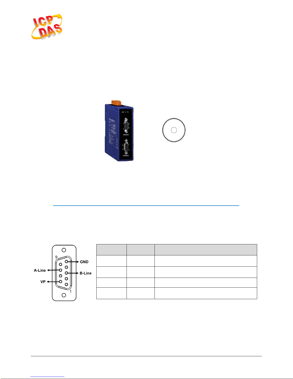
The PROFIBUS connector is a standard 9-pin D-Sub connector, there
are only 4 pins used in PROFI-25xx module. The pins VP and GND
support the 5 volt power to active terminal resistor, and the A-Line and
B-Line is the data bus.
Pin No.
Signal
Meaning
3
B-Line
Receive/Transmit data – plus
5
GND
Power ground of active terminator
6
VP
Power 5 volt of active terminator
8
A-Line
Receive/Transmit data - minus
Page 2
PROFI-2510
PROFI-2541(SC)
PROFI-2542(SC)
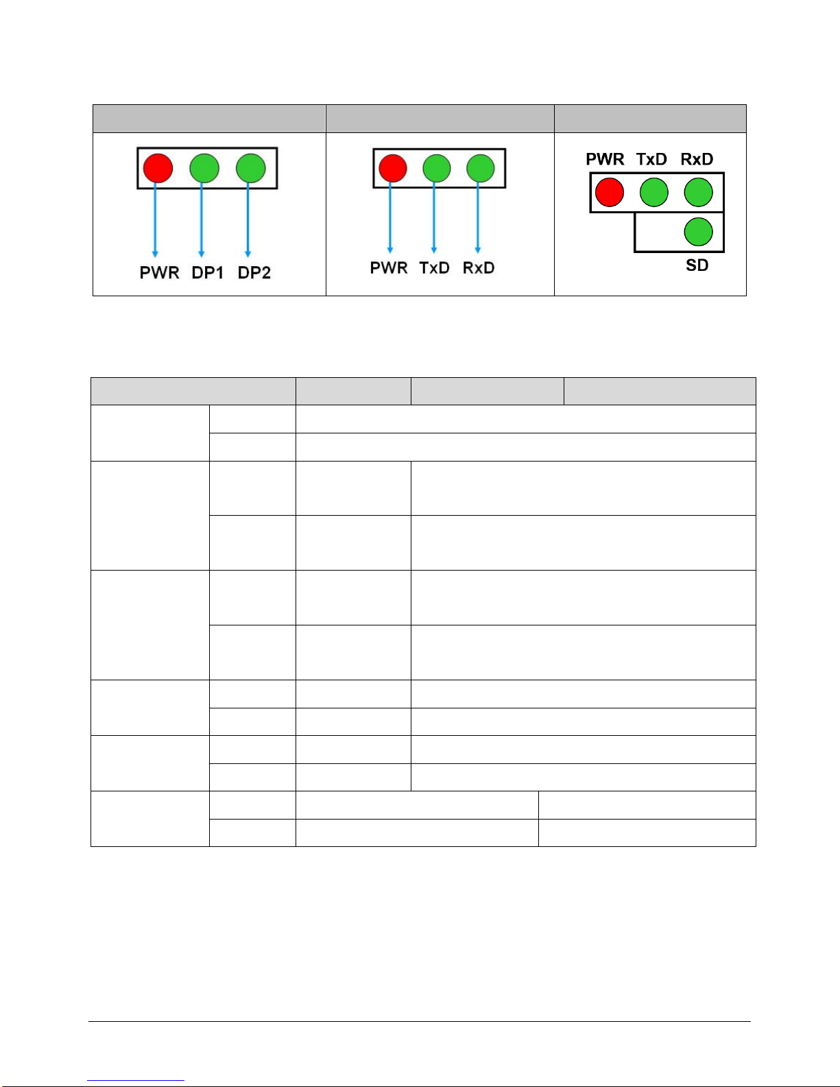
It provides three status indicators,
PROFI-2510
PROFI-2541(SC)
PRPOFI-2542(SC)
PWR (Red)
ON
Module Active
OFF
Module Inactive
DP1 (Green)
Flashing
Data
Transmitting
N/A
OFF
No Data
Transmitting
N/A
DP2 (Green)
Flashing
Data
Transmitting
N/A
OFF
No Data
Transmitting
N/A
TxD (Green)
Flashing
N/A
Data Transmitting
OFF
N/A
No Data Transmitting
RxD (Green)
Flashing
N/A
Data Transmitting
OFF
N/A
No Data Transmitting
SD (Green)
ON
N/A
Fiber Signal Detected
OFF
N/A
No Fiber Signal Detected
Page 3
3
Terminating Resistors
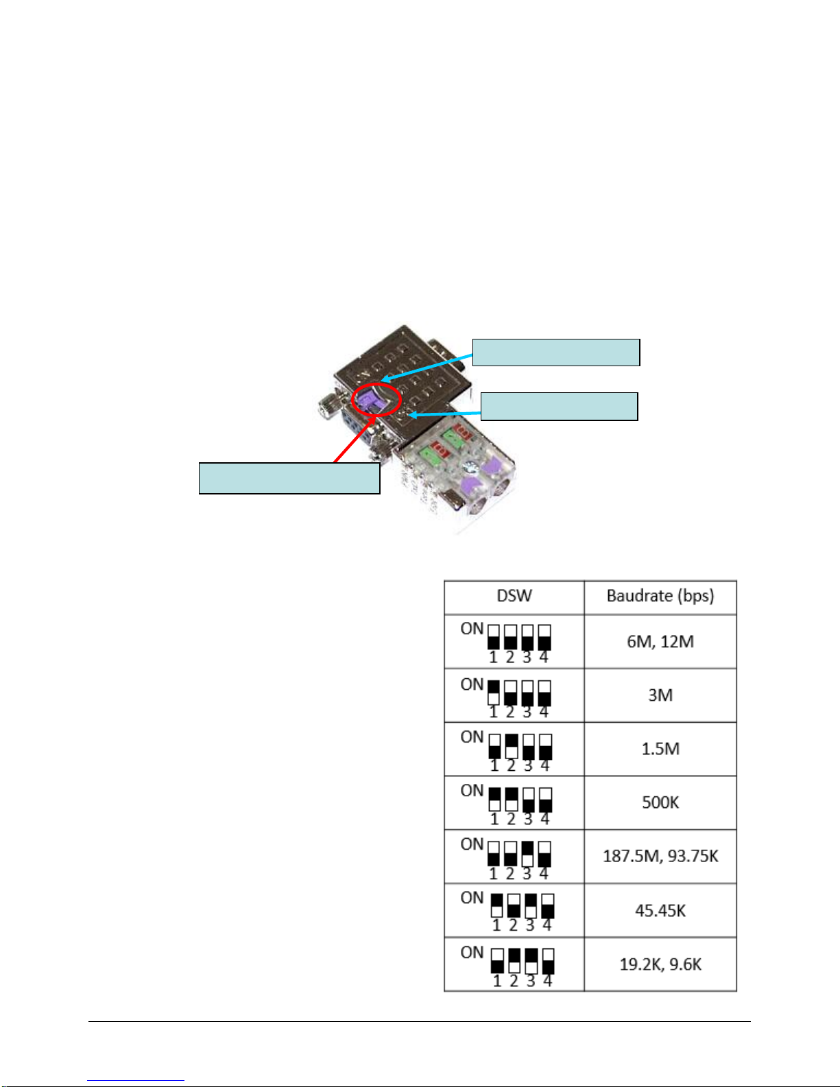
In order to minimize the reflection effect of the signal transmission,
PROFIBUS device has to fit with an active terminal resistor at both first
node and last node. The connection of active terminating resistors is
shown in above circuit diagram. The PROFI-25xx module doesn’t have
any terminating resistors inside. Therefore, users must add the
terminator in external. In general, PROFIBUS connector has terminating
resistors inside, and there is a switch to control the ON/OFF of the
terminating resistors, as shown below.
4
Dip Switch
Users can set dip switch to get a
better PROFIBUS signal quality in
PROFI-2542(SC) module.
Terminator Switch
Terminator OFF
Terminator ON
Page 4
5
Wire Connections
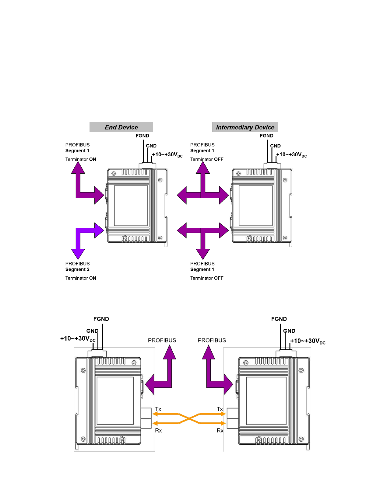
PROFI-2510
If PROFI-2510 is an end device of PROFIBUS segment 1 and
PROFIBUS segment 2. The terminal resistor of segment 1 is ON.
The terminal resistor of segment 2 is ON.
If PROFI-2510 is an intermediary device of PROFIBUS segment 1.
The terminal resistor of segment 1 is OFF.
PROFI-2541(SC) / PROFI-2542(SC)
 Loading...