

Page 1
ICP DAS Co., LTD PM-3133 Quick Start V1.20 Page 1
PM-3133 Quick Start
1. Shipping Package
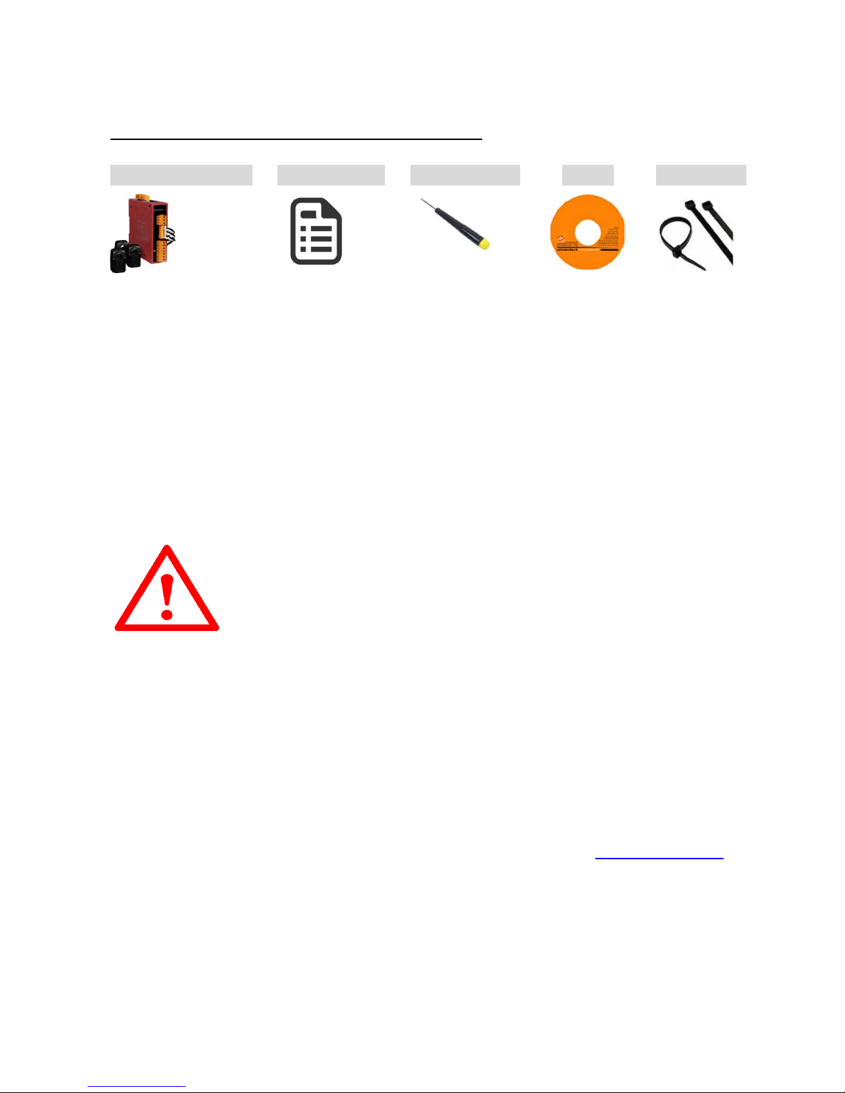
This shipping package contains the following items
1 x PM-3133 module 1 x Quick Start Screw Driver x 1 CD x 1 Cable ties x 3
2. PM-3133 introduction
ICP DAS offers PM-3133 family in a full range of Single-phase and Three-phase smart power meters for power
monitoring. The products offer a rich feature set combined with easy-to-int egra te c ommunications.
With its high accuracy (<0.5%, PF=1), the PM-3133 series products can be applied both on low voltage primary
side and/or medium/high voltage secondary side and enable the users to obtain in real time the reliable and
accurate energy consumption readings from the monitored equipments while in operation. These compact size
and cost effective Power Meters are equipped with revolutionary wired clip-on CT (various types support input
current up to 200A) and standard Modbus communication RS-485 protocol for easy deployment. It works with
input voltages ranging 10V ~ 500V, supporting a wide range of applications.
2.1. Caution & Warning
The meter contains hazardous voltages, and should never be disassembled. Failing to follow
this practice will result in serious injury or death. Any work on or near energized meters,
meter sockets, or other metering equipment could induce a danger of electrical shock. It is
strongly recommended that all work should be performed only by qualified industrial
electricians and metering specialist. ICP DAS assumes no responsibility if your electrical installer does not follow
the appropriate national and local electrical codes.
ICP DAS assumes no liability for any damage resulting from the use of this product. ICP DAS reserves the right to
change this manual at any time without notice. The information furnished by ICP DAS is believed to be accurate
and reliable. However, no responsibility is assumed by ICP DAS for its use, not for any infringements of patents or
other rights of third parties resulting from its use.
2.2. Product Warranty & Customer Support
ICP DAS warrants all products free from defects in material and workmanship for a period of one year from the
date of shipping. During the warranty period, we will, at our position, either repair or replace any product that
proves to be defective. To report any defect, please contact :+886-3- 597-3366 or [email protected]
.
2.2.1. Limitation of Warranty
This warranty does not apply to defects resulting from unauthorized modification, misuse, or use for reason other
than electrical power monitoring. The supplied meter is not a user-serviceable product.
3. Installation
Please use the soft dry clothes to clean the instrument.
Please do not use any chemical or detergent or volatile solvents to clean the instrument, in order to avoid any
possibility of the cover damage.
Page 2

ICP DAS Co., LTD PM-3133 Quick Start V1.20 Page 2
3.1.
Dimension: 127mm(length)× 33mm(wide)× 105mm(high)
Products come with external split type clip-on CT’s. Disconnect the CT’s or use other CT’s is highly
prohibited.
Please read this operation manual carefully before using.
Please re-confirm the measure position.
Reconfirm the RST (ABC) phase sequence of the power system.
PM-3133 series can be installed as rail mounting mode or embedded, no need to drill a hole or screw to fix it
(rail mounting width can up to the length of 35 mm).
Meter auxiliary power for PM-3133 series is DC +12V ~+48V.
3.2. V oltage Input
1. PM-3133 series: Input Voltage up to 500V.
For any higher Input Voltage large than 500V, please add the PT (power transformer), and Change PT RATIO
setup.
2. Confirm the RST (ABC) phase sequence.
3.3. Current Input
1. The external CT’s are fragile, please handle with care.
2. The current input of PM-3133 series is in mA range. Only the ex-factory attached CT’s can be used. The other
CT’s, for example, from panel will damage the instrument due to its large current (around 5A).
3. The current input of PM-3133-xxxP series is in mV range. Only the ex-factory attached CT’s can be used. The
other CT’s, for example, from panel will damage the instrument due to its large current (around 5A or mA).
4. When more than one smart meter (PM-3133 series) are installed, please do not disconnect the CT with its
original meter and mix use with each other. Since each set of smart meter (PM-3133 series) and its attached
split type clip-on CT are calibrated set by set. The mix use may cause wrong measurements.
5. To install CT’s correctly, please ensure the CT lines sequences is right before clip the CT’s onto the power
cable of the monitoring equipment. (Detail will be found in next section)
6. When measuring the current, the secondary circuit of a CT should never be opened
when a load is passing through its primary. Make sure you always open the CT clip to
detach the CT before removing the terminal lines. Otherwise, it will cause severe injury.
7. Please handle with extra care, especially when the operation space of CT’s is limited.
8. The current direction must follo w K -L marked on CT’s.
9. Please select the right size CT’s for different size of monitoring equipment cables:
power cable diameter <Φ10 use 60A CT,Φ10~Φ16 use 100A CT,Φ16~Φ24 use 200A CT
,Φ24~Φ36 use 300A or 400A CT。
10. The maximum current value cannot exceed the CT rating.
Page 3
ICP DAS Co., LTD PM-3133 Quick Start V1.20 Page 3
3.4. Connection
PM-3133
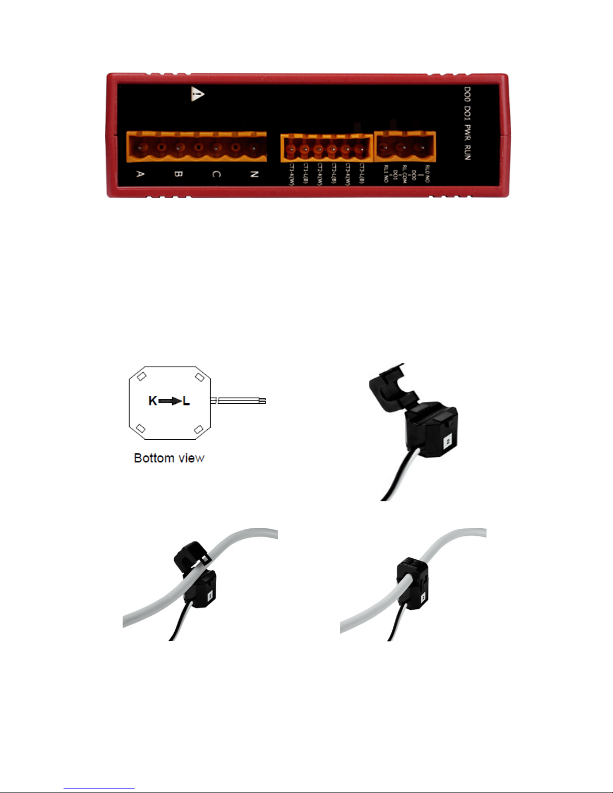
Please firstly check the current input terminal, and then in white black, white black, white black wire
sequences (CT1-K,CT1-L,CT2-K,CT2-L,CT3-K,CT3-L). Then connect the CT’s, and close the CT clip. Make
sure the arrow direction sign on CT’s follows current flow direction(K→L)
Note: it must be in the same direction.
Connect the voltage input terminal N C B A. for PM-3133, in the three phase order as follows on N C B A.
Attention please!! For 3P3W-2CT, connect in N C A phase sequence, do not connect phase B
(Check the diagram).
3.5. CT’s installation steps
At the bottom of the CT, there is a “K→L”
mark.
Open the CT clip.
Make sure the power current direction follow
the “K→L” mark on the CT and then close
the CT clip.
Installation steps finished.
Page 4
ICP DAS Co., LTD PM-3133 Quick Start V1.20 Page 4
3.6. Wiring
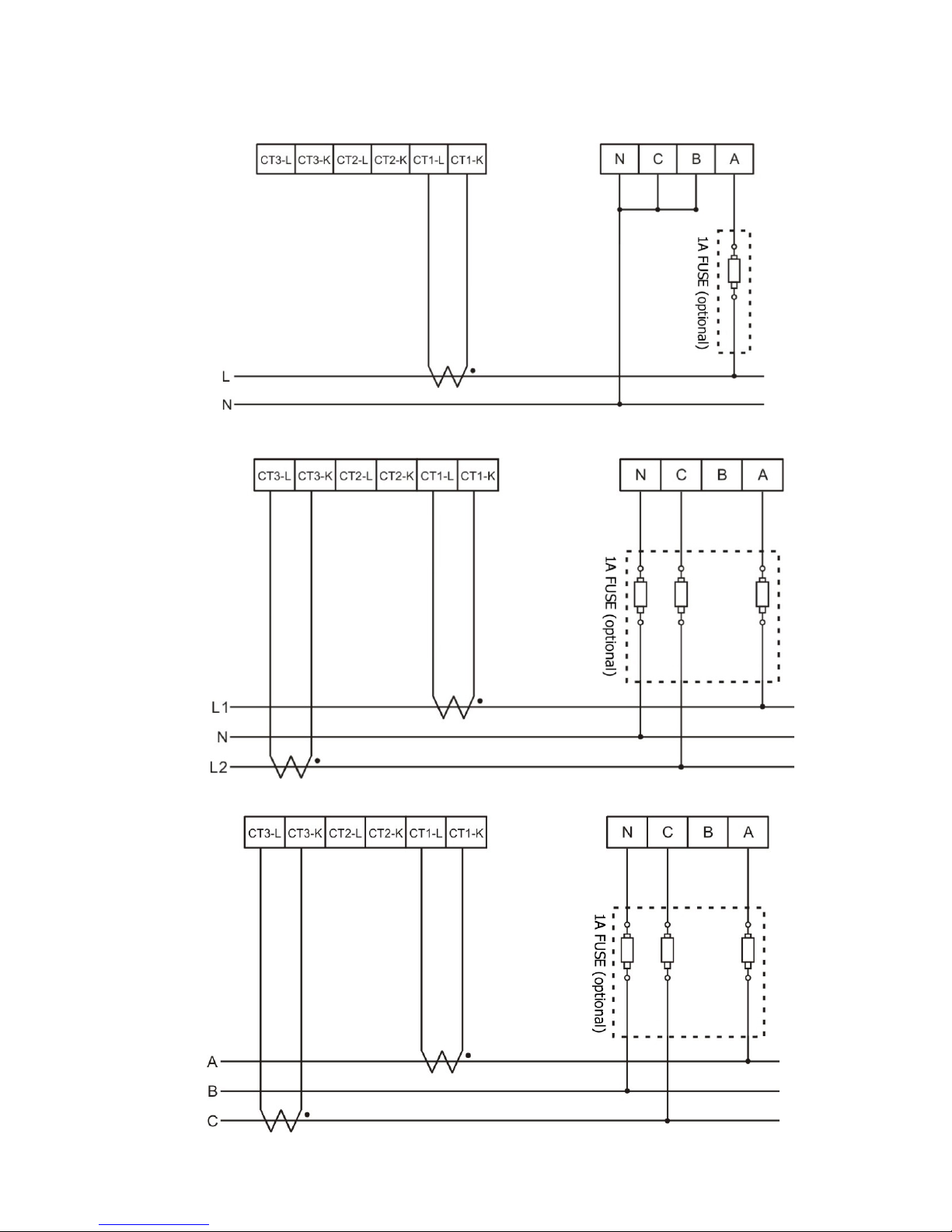
1P2W-1CT(PM-3133)
1P3W-2CT(PM-3133)
3P3W-2CT(PM-3133)
Page 5
ICP DAS Co., LTD PM-3133 Quick Start V1.20 Page 5
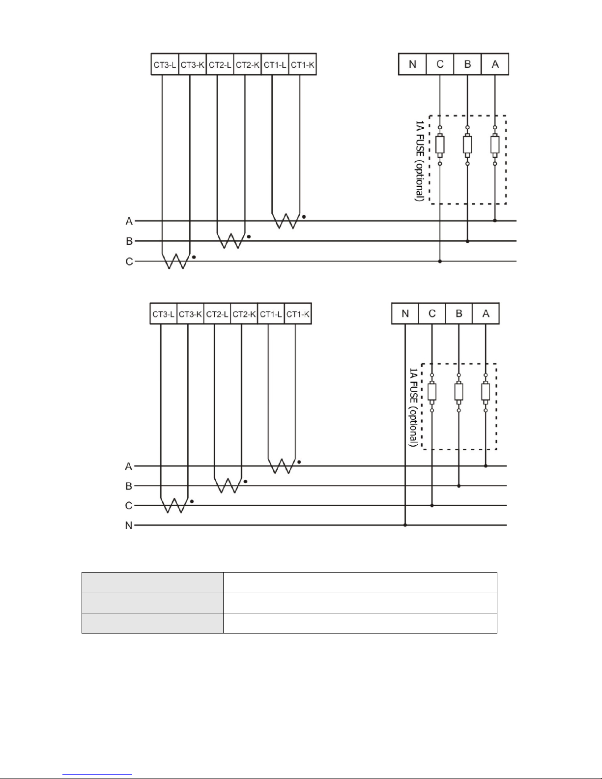
3P3W-3CT(PM-3133)
3P4W-3CT(PM-3133)
4. Relay Output & LED Indicator
Re l ay Output
Relay type Power Relay, Form A (SPST N.O.)
Operating Voltage Range 250 VAC / 30 VD C
Max. Load Current 5 A at 25 °C
LE D I ndi cator
The PM-3133 has 4 LED to indicate the unit power status, communication, and power
data calculation.
RUN: Green, light up after communication ready. LED will flash when the unit is
processing communication.
PWR: Red, Power on LED always on.
DO0: Green. LED DO0 will light up, when DO0 is “ON”.
DO1: Green. LED
DO1 will light up, when DO1 is “ON”.
Page 6
ICP DAS Co., LTD PM-3133 Quick Start V1.20 Page 6
5. Communication
5.1. RS-485 & CAN setting
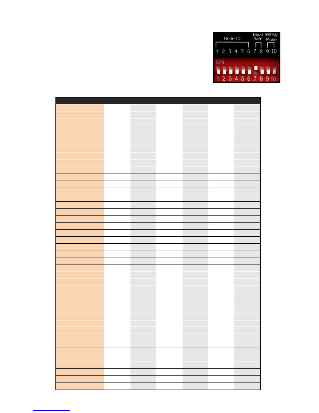
Default setting for RS-485: 19200, n, 8, 1 ,for CAN: 125K bps
DIP switch (SW1-SW6) is used for Modbus address(or CANopen Node
ID) setting, default is 1, i.e. all OFF
For example: Modbus address(or CANopen Node ID) is 10,find the
table of DIP switch 1-6 is ON, OFF, OFF, ON, OFF, OFF
SW1-SW6 setting
Setting Modbus-RTU address for communication (1-64)
Modbus Address
SW 1
SW 2
SW 3
SW 4
SW 5
SW 6
1
OFF
OFF
OFF
OFF
OFF
OFF
2
ON
OFF
OFF
OFF
OFF
OFF
3
OFF
ON
OFF
OFF
OFF
OFF
4
ON
ON
OFF
OFF
OFF
OFF
5
OFF
OFF
ON
OFF
OFF
OFF
6
ON
OFF
ON
OFF
OFF
OFF
7
OFF
ON
ON
OFF
OFF
OFF
8
ON
ON
ON
OFF
OFF
OFF
9
OFF
OFF
OFF
ON
OFF
OFF
10
ON
OFF
OFF
ON
OFF
OFF
11
OFF
ON
OFF
ON
OFF
OFF
12
ON
ON
OFF
ON
OFF
OFF
13
OFF
OFF
ON
ON
OFF
OFF
14
ON
OFF
ON
ON
OFF
OFF
15
OFF
ON
ON
ON
OFF
OFF
16
ON
ON
ON
ON
OFF
OFF
17
OFF
OFF
OFF
OFF
ON
OFF
18
ON
OFF
OFF
OFF
ON
OFF
19
OFF
ON
OFF
OFF
ON
OFF
20
ON
ON
OFF
OFF
ON
OFF
21
OFF
OFF
ON
OFF
ON
OFF
22
ON
OFF
ON
OFF
ON
OFF
23
OFF
ON
ON
OFF
ON
OFF
24
ON
ON
ON
OFF
ON
OFF
25
OFF
OFF
OFF
ON
ON
OFF
26
ON
OFF
OFF
ON
ON
OFF
27
OFF
ON
OFF
ON
ON
OFF
28
ON
ON
OFF
ON
ON
OFF
29
OFF
OFF
ON
ON
ON
OFF
30
ON
OFF
ON
ON
ON
OFF
31
OFF
ON
ON
ON
ON
OFF
32
ON
ON
ON
ON
ON
OFF
33
OFF
OFF
OFF
OFF
OFF
ON
34
ON
OFF
OFF
OFF
OFF
ON
35
OFF
ON
OFF
OFF
OFF
ON
36
ON
ON
OFF
OFF
OFF
ON
37
OFF
OFF
ON
OFF
OFF
ON
38
ON
OFF
ON
OFF
OFF
ON
39
OFF
ON
ON
OFF
OFF
ON
40
ON
ON
ON
OFF
OFF
ON
41
OFF
OFF
OFF
ON
OFF
ON
Page 7
ICP DAS Co., LTD PM-3133 Quick Start V1.20 Page 7
42
ON
OFF
OFF
ON
OFF
ON
43
OFF
ON
OFF
ON
OFF
ON
44
ON
ON
OFF
ON
OFF
ON
45
OFF
OFF
ON
ON
OFF
ON
46
ON
OFF
ON
ON
OFF
ON
47
OFF
ON
ON
ON
OFF
ON
48
ON
ON
ON
ON
OFF
ON
49
OFF
OFF
OFF
OFF
ON
ON
50
ON
OFF
OFF
OFF
ON
ON
51
OFF
ON
OFF
OFF
ON
ON
52
ON
ON
OFF
OFF
ON
ON
53
OFF
OFF
ON
OFF
ON
ON
54
ON
OFF
ON
OFF
ON
ON
55
OFF
ON
ON
OFF
ON
ON
56
ON
ON
ON
OFF
ON
ON
57
OFF
OFF
OFF
ON
ON
ON
58
ON
OFF
OFF
ON
ON
ON
59
OFF
ON
OFF
ON
ON
ON
60
ON
ON
OFF
ON
ON
ON
61
OFF
OFF
ON
ON
ON
ON
62
ON
OFF
ON
ON
ON
ON
63
OFF
ON
ON
ON
ON
ON
64
ON
ON
ON
ON
ON
ON
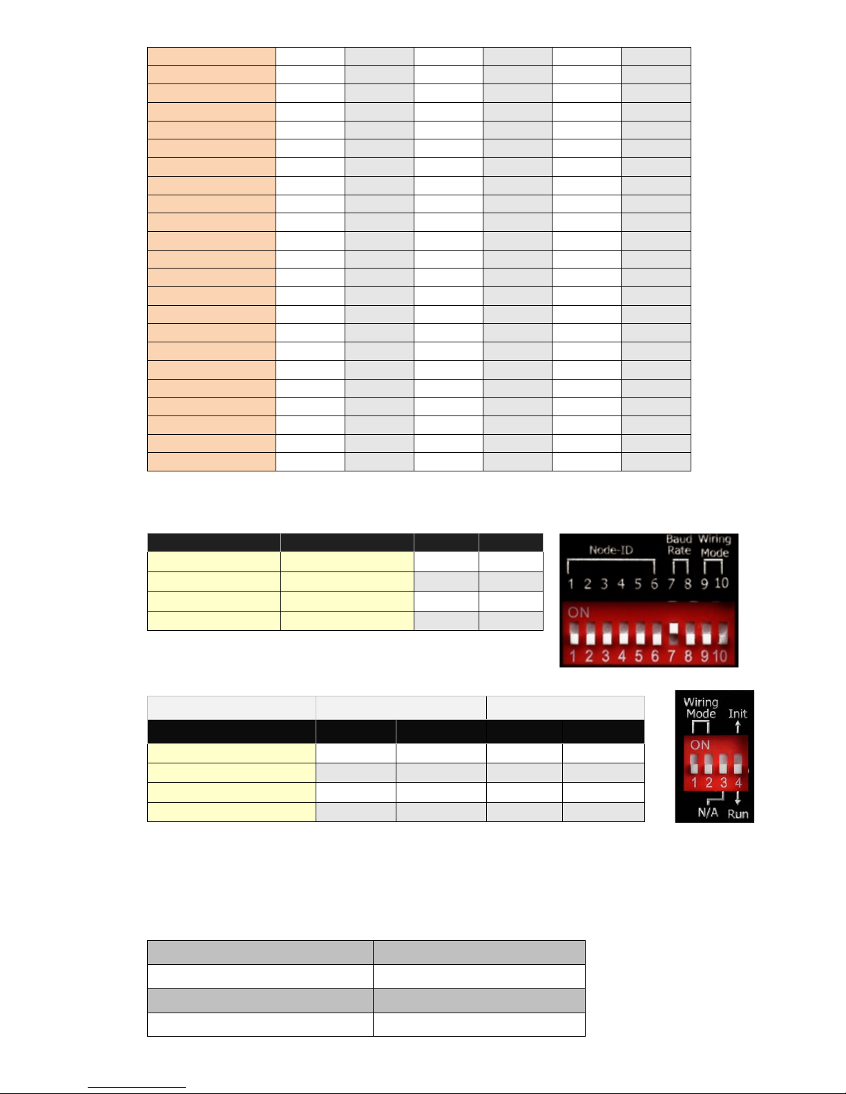
SW7-SW8 For Baud Rate Setting
RS-485
CAN
SW 7
SW8
9600 bps
125k(Default) bps
OFF
OFF
19200 (Default) bps 250k bps
ON
OFF
38400 bps
500k bps
OFF
ON
115200 bps
1M bps
ON
ON
PM-3133:Select the different wiring mode
(Please select the Software setting, if 1P2W-1CT or 1P3W-2CT is used)
Models
PM-3133 PM-3133-MTCP
Wiring
SW 9 SW 10 SW 1 SW 2
Software setting
OFF
OFF
OFF
OFF
3P3W-2CT
ON
OFF
ON
OFF
3P3W-3CT
OFF
ON
OFF
ON
3P4W-3CT
ON
ON
ON
ON
5.2. Add the Bias Resistor on RS-485 Network for stable signal
The RS-485 master is required to provide the bias for PM-31xx series. Otherwise, the tM-SG4 or SG-785
should be added to provide the bias. All ICP DAS controllers and converters provide the bias.
5.3. Ethernet setting
Ethernet default settings:
IP Address 192.168.255.1
Subnet mask 255.255.0.0
Gateway 192.168.0.1
Port 502
Page 8
ICP DAS Co., LTD PM-3133 Quick Start V1.20 Page 8
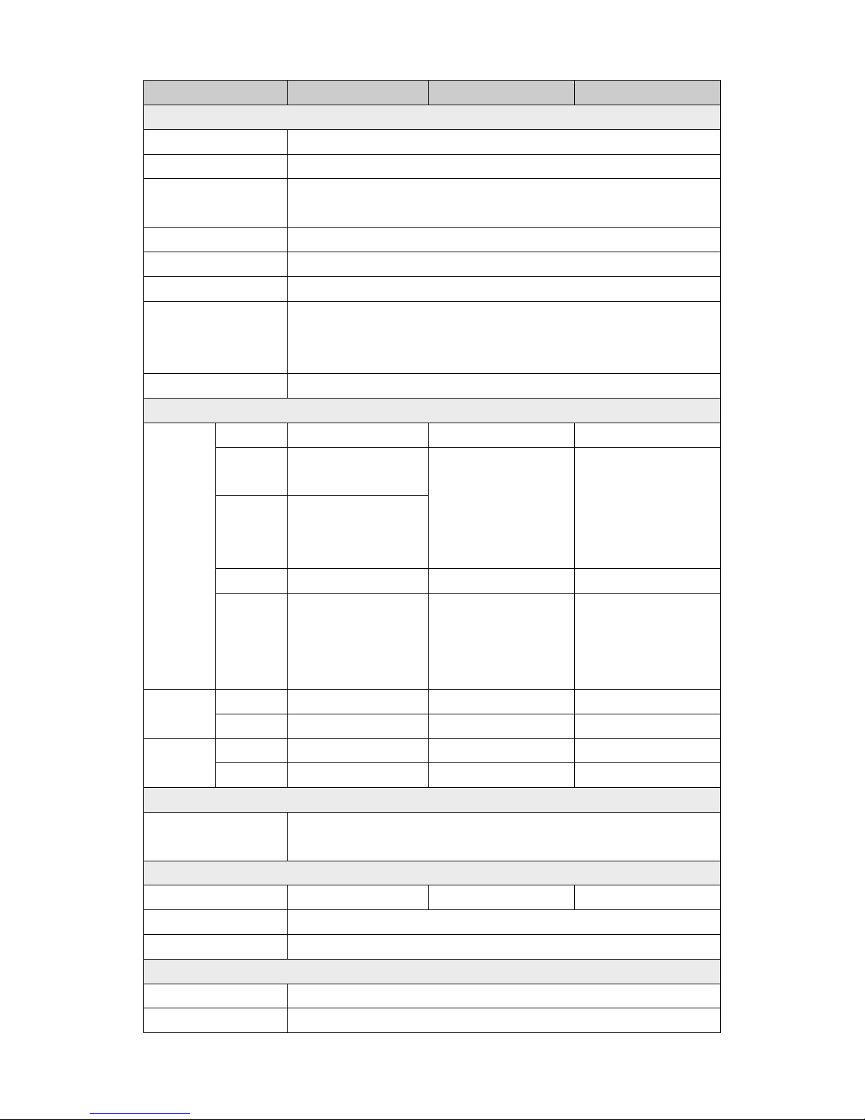
5.4. Specifications
Model PM-3133 PM-3133-MTCP PM-3133-CPS
AC Power Measurement
Wiring 1P2W-1CT, 1P3W-2CT, 3P3W-2CT, 3P3W-3CT and 3P4W-3CT
Input Voltage 10 ~ 500 V (CAT III); Input Frequency: 50/60 Hz
InputCurrent
CT Φ10 mm (60 A); CTΦ16 mm (100 A); CTΦ24 mm (200 A); CTΦ36 mm (300 A); CTΦ36
mm (400 A)
Input Frequency 50/60 Hz
W Accuracy Better than 0.5% (PF = 1 )
Starting Current >0.03A ( 60A ), >0.05A (100A ), >0.09A( 200A )
Power Parameter
Measurement
True RMS voltage (Vrms), True RMS current (Irms), Active Power (kW), Active Energy
(kWh), Apparent Power (kVA), Apparent Energy (kVA h),
Reactive Power (kVAR), Reactive Energy (kVARh), Power Factor (PF)
Data Update Rate 1 Second
Communication
RS-485
Protocol Modbus-RTU - Baud rate
9600,19200 (default), 38400,
115200;
- -
Data format
N,8,1 (default); N,8,2;
E,8,1; E,8,2;
O,8,1; O,8,2
Isolation 3000 VDC - -
Bias Resistor
No (Usually supplied by
the RS-485 Master.
Alternatively, add a tM-
SG4
or SG-785)
- -
Ethernet
Protocol - Modbus TCP PoE - Yes, IEEE 802.3af
CAN Bus
Protocol
- -
CANopen
Baud rate
- -
125 k,250k,500k and 1M
Alarm Output
Power Relay
Form A (Normal Open) x 2; Relay Contact Voltage Range: 5
A @ 250 VA C (47 ~ 63Hz), 5 A
@ 30 VDC
Power
Input Range +12 ~ 48 VDC +12 ~ 48 VDC/PoE +12 ~ 48 VDC
Power Consumption 2 W
Dimensions (W x L x H) 127 mm x 105 mm x 33 mm
Environment
Operating Te mperature -20 ~ +70 °C
Storage Te mperature -25 ~ +80 °C
 Loading...