

PISO-CAN400U-FD series
Resources
Quick Start
v1.0, Feb 2021
Packing List
In addition to this guide, the package includes the following items:
PISO-CAN400U-FD-T or
PISO-CAN400U-FD-D x 1
Technical Support
service@icpdas.com
www.icpdas.com
How to search for drivers, manuals and
spec information on ICP DAS website.
For Mobile Web
Model Name
For Desktop Web
Model Name
P1
1
---------------------------------------------------------------------
Installing the Hardware on PC
2
---------------------------------------------------------------------
Installing Windows Driver
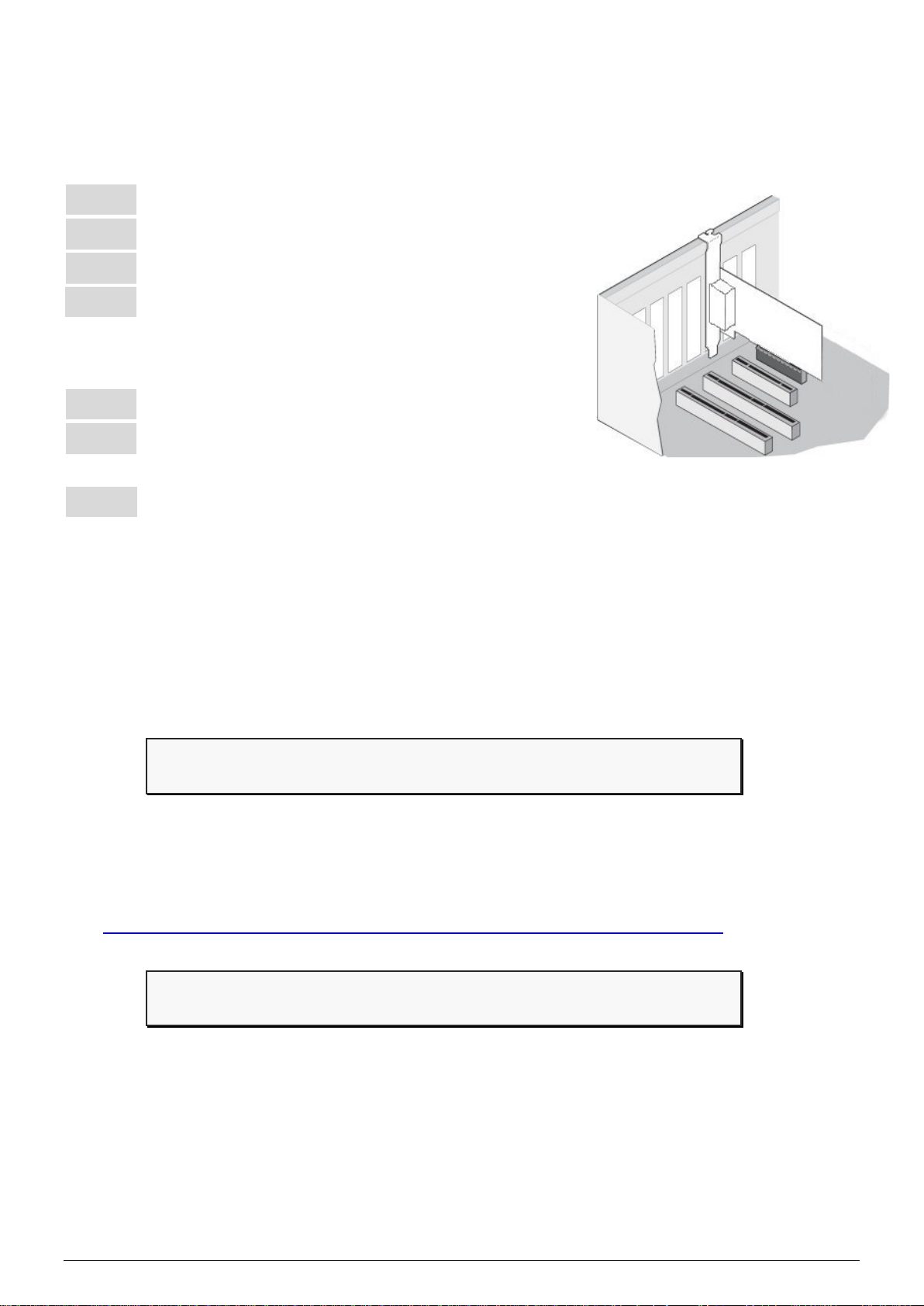
Step 1: Shut down and power off the computer.
Step 2: Remove all the covers from the computer.
Step 3: Select an unused PCI slot.
Step 4: Carefully insert the PISO-CAN400U-FD
series board into the PCI slot and secure the
board in place.
Step 5: Replace the covers on the computer.
Step 6: Reconnect the power supply and power on
the computer.
Step 7: Once the computer reboots, follow section 2 to install the
windows driver of PISO-CAN400U-FD series board.
Step 1: Download or locate the Windows driver.
The KP_CANFD driver supports 32/64-bit Windows 7/8.1/10. It is
recommended that new users install this driver, which can be found in
the following location.
https://www.icpdas.com/en/download/show.php?num=3200
Step 2: Start to install Windows driver.
(1). Right-click the Start button or press the Windows Logo + X key
combination on the keyboard and, from the list, click to select Device
Manager.
P2
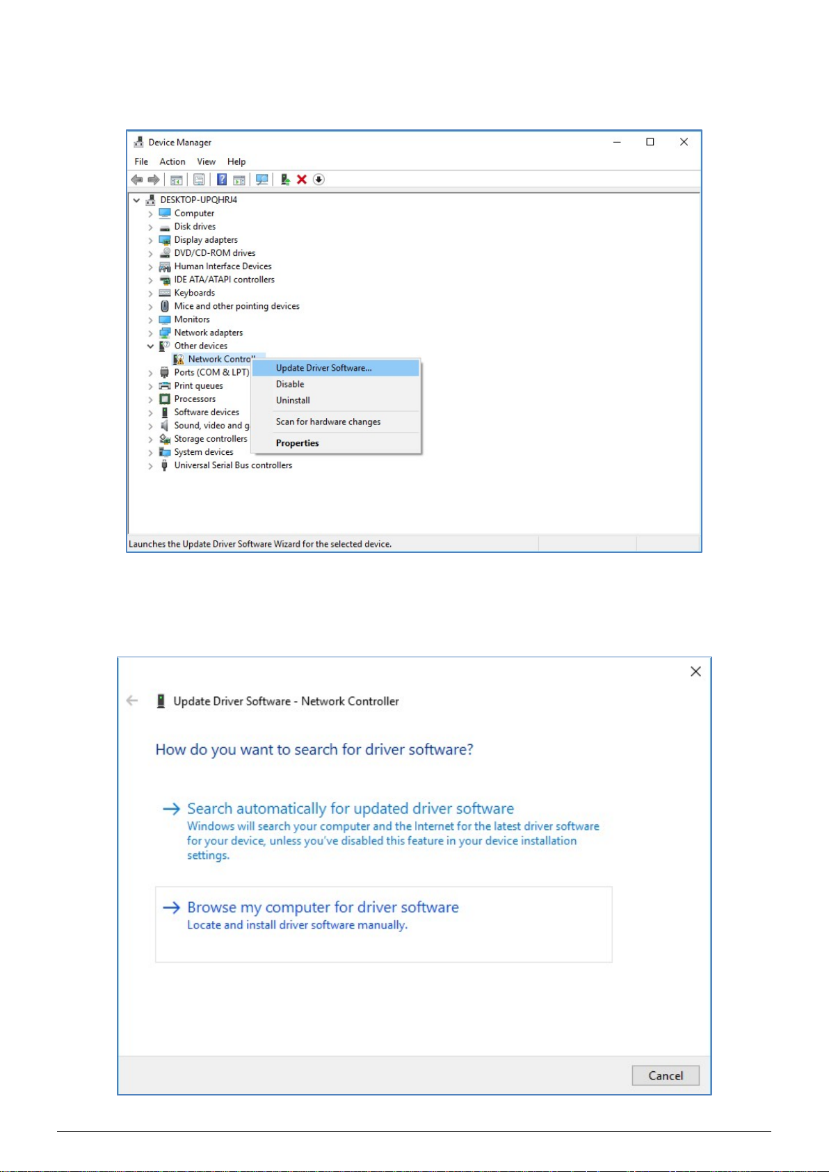
(2). On the Device Manager screen, select the Network Controller device from
Other devices item, then right-click the mouse button. Then select Update
Driver Software… to continue.
(3). On the Update Driver Software – Network Controller screen, click the
Browse my computer for driver software to continue.
P3

(4). Then Click the Browser… button to select the driver directory and click the
Next button to start to install the driver.
(5). Once the installation has been completed, click the Close button to exit.
P4

(6). After successfully to install the driver, you can see the
Pin
CAN_Low, signal line for the CAN
CAN_High, signal line for the CAN
3
----------------------------------------------------------------
PCM_PEX_PISO-CANFD Cards in CANFDCard item.
Pin Assignment
Pin Assignments for the 5-pin screw terminal connector
Name Description
No.
CAN_Gnd, signal line for the CAN
1 CAN_GND
port.
2 CAN_L
port.
3 F.G. Frame Ground.
4 CAN_H
5 N/A Not used
port.
P5

CAN_Low, signal line for the
CAN_Gnd, signal line for the
CAN_High, signal line for
4
----------------------------------------------------------------
Pin Assignments for the 9-pin Male D-Sub connector
Pin
Name Description
No.
1 N/A Not used
2 CAN_L
CAN port.
CAN_Gnd, signal line for the
3 CAN_GND
CAN port.
4 N/A Not used
5 N/A Not used
6 CAN_GND
CAN port.
7 CAN_H
the CAN port.
8 N/A Not used
9 N/A Not used
Testing Board
PISO-CANFD Utility is provided by ICP DAS to transmit / receive
CAN/CAN FD messages for CAN Bus communication testing easily
and quickly.
Step 1: Download the PISO-CANFD Utility
The software is located at:
https://www.icpdas.com/en/download/show.php?num=3199
P6

Step 2: Setting up the board
Connect the CAN_L and CAN_H pin on port1 and port2 of board.
Step 3: Active the board
Launch the PISO-CANFD Utility software.
P7

(1). Click the “Connect to …” item to open the “Connect” frame of Utility.
(2). Select the necessary PISO-CAN400U-FD module.
(3). On the “CAN Setting location, user can set the CAN operation mode, bit
rate and filter prarameters. For detail information, please refer to section
“2.4. Software Utility” of user’s manual.
(4). Press the “Active” buttom to start to use the above setting to send/receice
CAN messages.
Step 4: Send, receive CAN/CAN FD messages
By using the PISO-CANFD Utiltiy tool, user can send and receive
CAN/CAN FD messages via the board.
Send CAN/CAN FD messages and check received CAN/CAN FD
messages.
P8
 Loading...