

Page 1
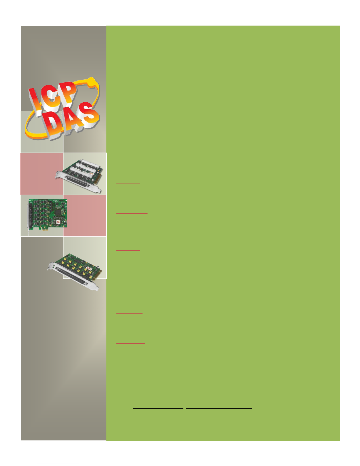
PIO-D96 Series Card
User Manual
96-channel DIO board Version 2.3, Jun. 2018
SUPPORTS
Board includes PIO-D96, PIO-D96U, PIO-D96SU and PEX-D96S.
WARRANTY
All products manufactured by ICP DAS are warranted against defective materials
for a period of one year from the date of delivery to the original purchaser.
WARNING
ICP DAS assumes no liability for damages consequent to the use of this product.
ICP DAS reserves the right to change this manual at any time without notice. The
information furnished by ICP DAS is believed to be accurate and reliable. However,
no responsibility is assumed by ICP DAS for its use, nor for any infringements of
patents or other rights of third parties resulting from its use.
COPYRIGHT
Copyright © 2018 by ICP DAS. All rights are reserved.
TRADEMARK
Names are used for identification only and may be registered trademarks of their
respective companies.
CONTACT US
If you have any question, please feel to contact us. We will give you quick
response within 2 workdays.
Email: [email protected], [email protected]
Page 2
PIO-D96 Series Card
96-channel DIO Board
User Manual, Ve r. 2.3, Jun. 2018, PMH-008-23 Page: 1
TABLE OF CONTENTS
PACKING LIST ....................................................................................................................................................................... 3
1. INTRODUCTION ................................................................................................................................................ 4
1.1 FEAT UR ES ............................................................................................................................................................ 5
1.2 SPECIFICATIONS .................................................................................................................................................... 6
2. HARDWARE CONFIGURATION ......................................................................................................................... 7
2.1 BOARD LAYOU T .................................................................................................................................................... 7
2.2 I/O PORT LOCATION ............................................................................................................................................. 9
2.3 CARD ID SWITCH ................................................................................................................................................ 10
2.4 PIN ASSIGNMENTS .............................................................................................................................................. 11
2.4.1 PIO-D96 and PIO-D96U .............................................................................................................................. 11
2.4.2 PIO-D96SU and PEX-D96S ......................................................................................................................... 12
2.5 ENABLE I/O OPERATION ..................................................................................................................................... 13
2.6 DI/DO ARCHITECTURE ....................................................................................................................................... 14
2.7 INTERRUPT OPER ATIO N ...................................................................................................................................... 15
3. HARDWARE INSTALLATION ............................................................................................................................ 16
4. SOFTWARE INSTALLATION ............................................................................................................................. 20
4.1 OBTAINING/INSTALLING THE DRIVER INSTALLER PACKAGE ................................................................................ 20
4.2 PNP DRIVER INSTALLATION ................................................................................................................................. 23
4.3 VERIFYING THE INSTALLATION ............................................................................................................................. 25
4.3.1 Accessing Windows Device Manager .......................................................................................................... 25
4.3.2 Check that the Installation .......................................................................................................................... 28
5. BOARD TESTING .............................................................................................................................................. 29
5.1 SELF-TEST WIRING ............................................................................................................................................ 29
5.1.1 PIO-D96/D96U ............................................................................................................................................ 29
5.1.2 PIO-D96SU/PEX-D96S .................................................................................................................................. 30
5.2 LAUNCH THE TEST PROGRAM............................................................................................................................... 31
6. I/O CONTROL REGISTER ................................................................................................................................. 34
6.1 HOW TO FIND THE I/O ADDRESS ......................................................................................................................... 34
6.2 THE ASSIGNMENT OF I/O ADDRESS...................................................................................................................... 38
6.3 THE I/O ADDRESS MAP ...................................................................................................................................... 40
6.3.1 RESET\ Control Register............................................................................................................................... 41
Page 3
PIO-D96 Series Card
96-channel DIO Board
User Manual, Ve r. 2.3, Jun. 2018, PMH-008-23 Page: 2
6.3.2 AUX Control Register ................................................................................................................................... 41
6.3.3 AUX Data Register ....................................................................................................................................... 42
6.3.4 INT Mask Control Register ........................................................................................................................... 42
6.3.5 Aux Status Register ..................................................................................................................................... 43
6.3.6 Interrupt Polarity Register ........................................................................................................................... 43
6.3.7 I/O Selection Control Register ..................................................................................................................... 44
6.3.8 Card ID Register ........................................................................................................................................... 45
6.3.9 Read/Write 8-bit Data Register ................................................................................................................... 45
7. DEMO PROGRAMS ........................................................................................................................................... 46
7.1 DEMO PROGRAM FOR WINDOWS .......................................................................................................................... 46
7.2 DEMO PROGRAM FOR DOS .................................................................................................................................. 48
APPENDIX: DAUGHTER BOARD ............................................................................................................................... 49
A1. DB-37, DN-37, DN-50 AND DN-100 ........................................................................................................................ 49
A2. DB-8125 .................................................................................................................................................................. 50
A3. ADP-37/PCI AND ADP-50/PCI ................................................................................................................................ 50
A4. DB-24P AND DB-24PD ISOLATED INPUT BOARD ......................................................................................................... 51
A5. DB-24R AND DB-24RD RE LAY BOA RD ....................................................................................................................... 52
A6. DB-24PR, DB-24POR AND DB-24C .............................................................................................................................. 53
A7. DAUGHTER BOARDS COMPARISON TABLE ........................................................................................................................... 54
Page 4
PIO-D96 Series Card
96-channel DIO Board
User Manual, Ve r. 2.3, Jun. 2018, PMH-008-23 Page: 3
Packing List
The shipping package includes the following items:
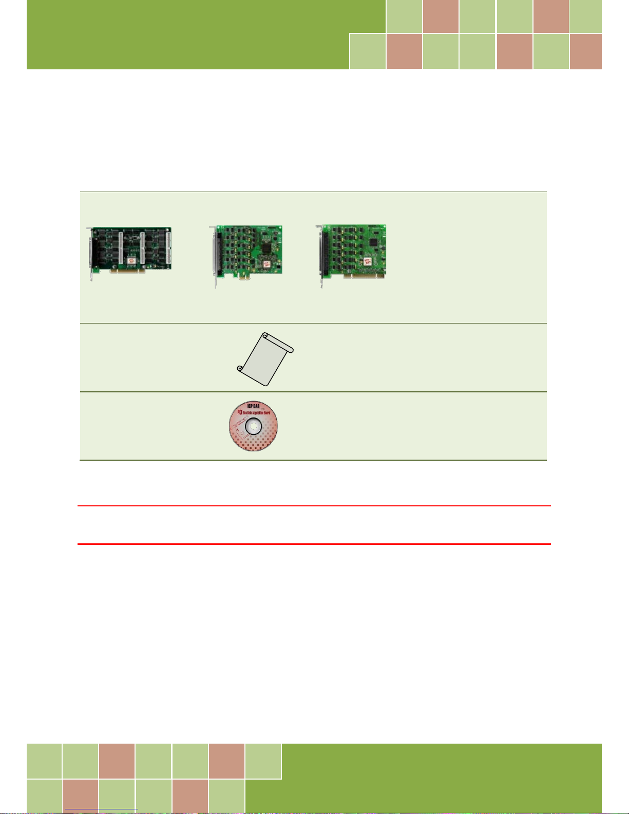
One PIO-D96 Series card as follows:
One printed Quick Start Guide
One Software Utility CD
Note:
If any of these items is missing or damaged, contact the dealer from whom you purchased the product. Save
the shipping materials and carton in case you need to ship or store the product in the future.
PIO-D96/D96U PEX-D96S
PIO-D96SU
Page 5
PIO-D96 Series Card
96-channel DIO Board
User Manual, Ve r. 2.3, Jun. 2018, PMH-008-23 Page: 4
1. Introduction
The PEX-D96S and PIO-D96U/D96SU cards are the new generation product that ICP DAS provides to
meet RoHS compliance requirement, and is designed as an easy replacement for the PIO-D96,
without requiring any modification to the software or the driver.
The PIO-D96U/D96SU universal PCI card supports 3.3 V/5 V PCI bus while the PEX-D96S supports
PCI Express bus. These cards provide 96 TTL Digital I/O lines that consist of twelve 8-bit
bi-directional ports. Each group of three 8-bit ports is arranged on the connector as Port A (PA), Port
B (PB) and Port C (PC), respectively, and all ports are configured as inputs ports on power-up or
after a reset.
The PIO-D96U provides four connectors for I/O wiring, while the PIO-D96SU and PEX-D96S provides
a single high-density connector that reduces the amount of installation space required for the card
in the computer.
The PIO-D96U/D96SU and PEX-D96S cards include an onboard Card ID switch that enables the
board to be recognized via software if two or more boards are installed in the same computer. The
pull-high/low jumpers allow the DI status to be predefined instead of remaining floating if the DI
channels are disconnected or interrupted.
These cards support various OS such as Linux, DOS, Windows 98, Windows NT, Windows 2000,
32-/64-bit Windows XP/2003/2008/Vista/7 and Windows 8. It also provides the DLL and Active X
control, and various language sample programs in Turbo C++, Borland c++, Microsoft C++, Visual
C++, Borland Delphi, Borland C++ Builder, Visual Basic, C#.NET, Visual Basic.NET and LabVIEW to
help users to quickly and easily develop their applications.
Comparison Table
Model
Interface
DI Pull-High/Low
Card ID
Compatibility
Advantage
PEX-D96S PCI Express Yes Yes 5 V/CMOS
Low power consumption
Low temperature
PIO-D96SU Universal PCI Yes Yes 5 V/CMOS
Low power consumption
Low temperature
PIO-D96U Universal PCI Yes Yes 5 V/TTL
High DO Driving
(Output Capability)
PIO-D96
(Phased-out)
PCI Bus No No 5 V/TTL
High DO Driving
(Output Capability)
Page 6
PIO-D96 Series Card
96-channel DIO Board
User Manual, Ve r. 2.3, Jun. 2018, PMH-008-23 Page: 5
1.1 Features
Support the +5V PCI bus for PIO-D96
Support the +3.3/+5 V PCI bus for PIO-D96U/D96SU
Support the PCI Express x 1 for PEX-D96S
96 channels of digital I/O
Bi-direction programmable I/O ports under software control
All I/O lines buffered on the board
Twelve 8-bit bi-direction I/O ports
4 Interrupt source: P2C0, P5C0, P8C0, P11C0
Card ID function for PIO-D96U/D96SU and PEX-D96S
Pull-high/low jumpers for DI channels for PIO-D96U/D96SU and PEX-D96S
PIO-D96/D96U: one DB37 connector and three 50-pin box headers
PIO-D96SU/PEX-D96S: one SCSI II 100-pin connector
Buffer output for higher driving capability
Connects directly to DB-24PR, DB-24PD, DB-24RD, DB-24PRD, DB-16P8R, DB-24POR, DB-24SSR,
DB-24C or any OPTO-22 Compatible daughter boards
PIO-D96/D96U/D96SU: DIO response time is about 1 μs (1MHz)
PEX-D96S: DIO response time is about 500 kHz
SMD, short card, power saving
Page 7
PIO-D96 Series Card
96-channel DIO Board
User Manual, Ve r. 2.3, Jun. 2018, PMH-008-23 Page: 6
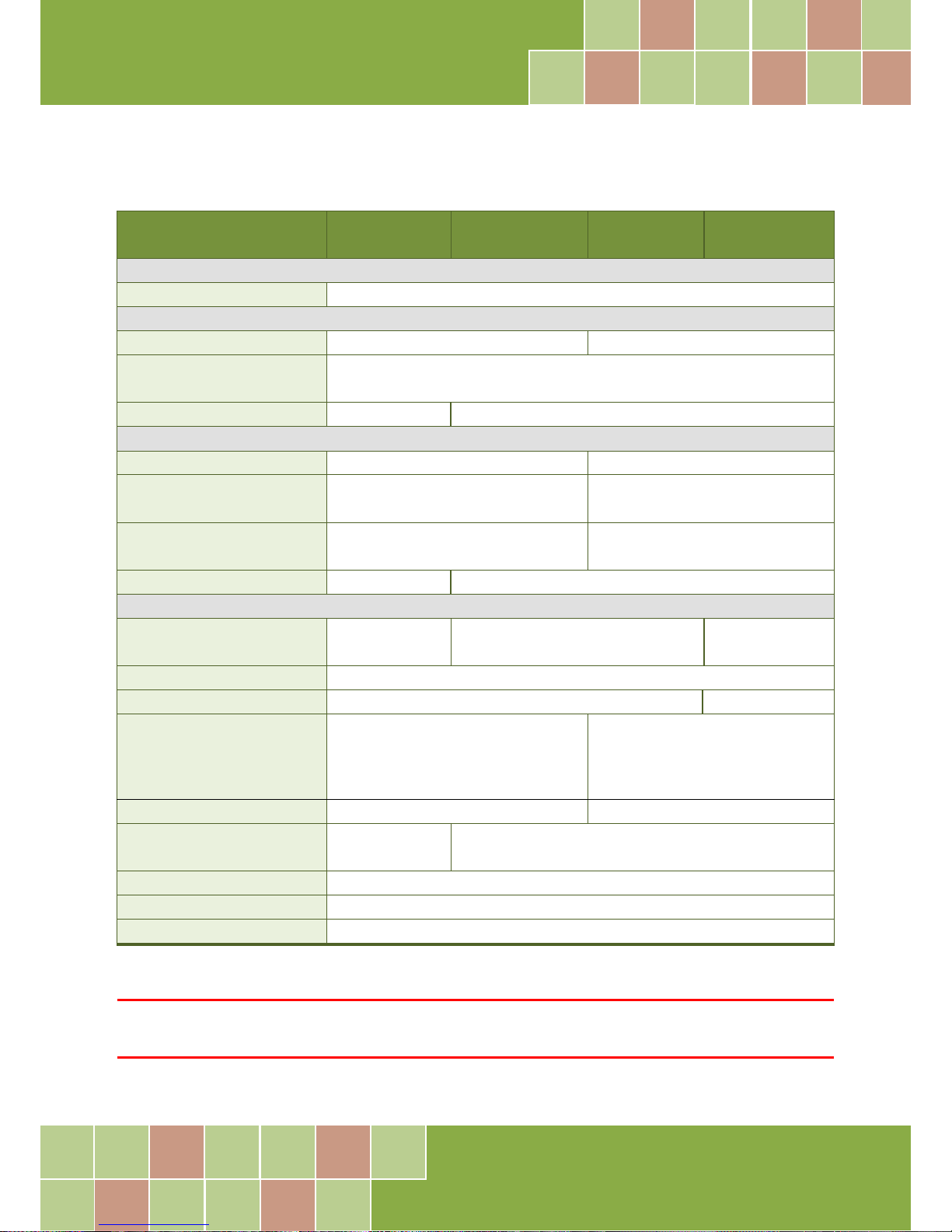
1.2 Specifications
Model Name PEX-D96S PIO-D96SU PIO-D96U PIO-D96
(Phased-out)
Programmable Digital I/O
Channels
96
Digital Input
Compatibility
5 V/COMS
5 V/TTL
Input Voltage
Logic 0: 0.8 V max.
Logic 1: 2.0 V min.
Response Speed
500 kHz
1 MHz
Digital Output
Compatibility
5 V/COMS
5 V/TTL
Output Voltage
Logic 0: 0.1 V max.
Logic 1: 4.4 V min.
Logic 0: 0.4 V max.
Logic 1: 2.4 V min.
Output Capability
Sink: 6 mA @ 0.33 V
Source: 6 mA @ 4.77 V
Sink: 64mA @ 0.8 V
Source: 32 mA @ 2.0 V
Response Speed
500 kHz
1 MHz
General
Bus T ype PCI Express x 1 3.3 V/5 V Unive rsal PCI, 32-bit, 33 MHz
5 V PCI, 32-bit, 33
MHz
Data Bus
8-bit
Card ID
Yes(4-bit)
No
I/O Connector Female SCSI II 100 pin x 1
Female DB37 x 1
50-pin box header x 3
Dimensions (L x W x D)
124 mm x 97 mm x 22 mm
180 mm x 105 mm x 22mm
Power Consumption
650 mA @ +3.3 V
0 mA @ +12 V
600 mA @ +5 V
Operating Temperature
0 ~ 60 °C
Storage Temperature
-20 ~ 70 °C
Humidity
5 ~ 85% RH, non-condensing
Note:
The I/O speed is depending on I/O card, bus speed, CPU speed and system loading. Any condition changes may cause
the I/O speed different.
Page 8
PIO-D96 Series Card
96-channel DIO Board
User Manual, Ve r. 2.3, Jun. 2018, PMH-008-23 Page: 7
2. Hardware Configuration
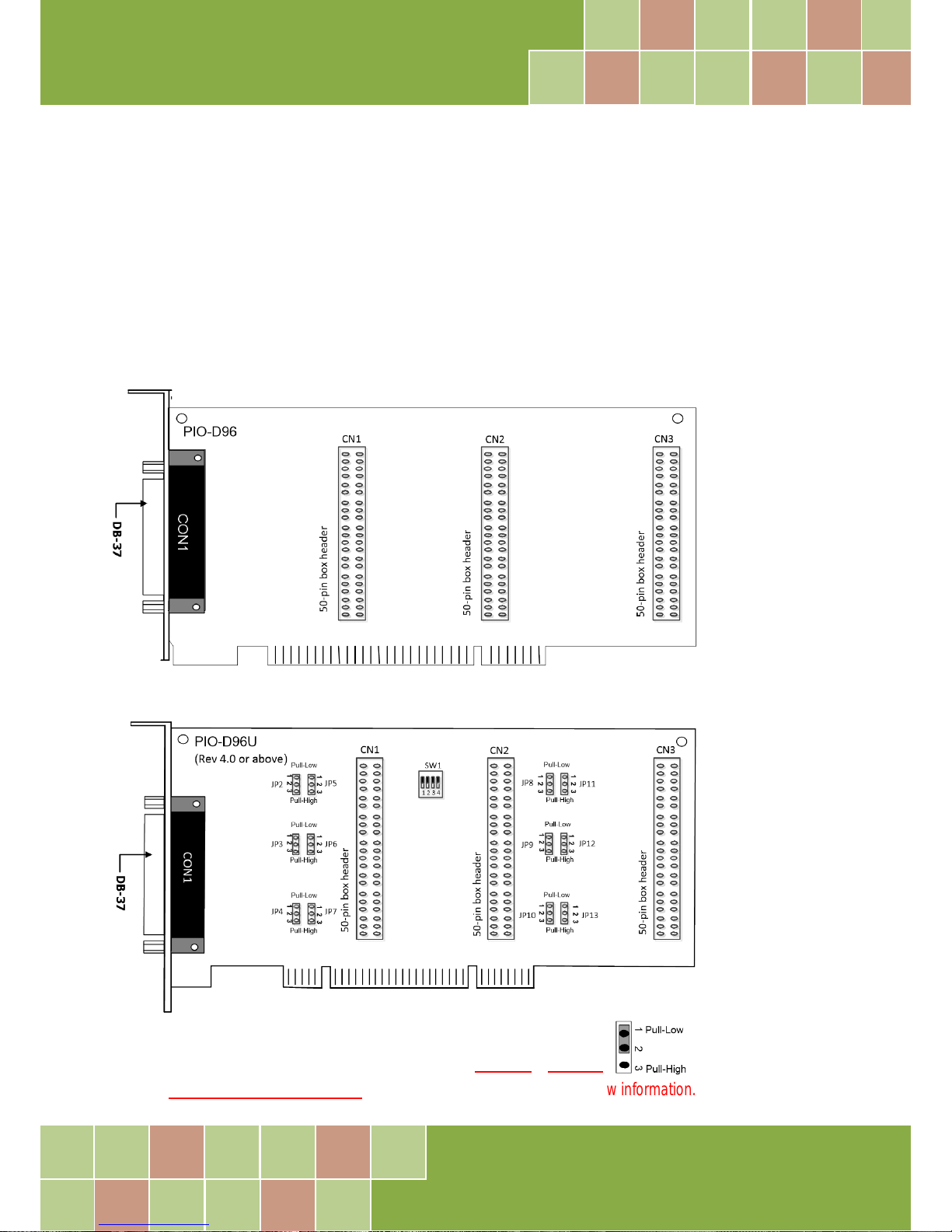
2.1 Board Layout
PIO-D96/PIO-D96U:
Note:
The JPx default settings: JP2/3/4/5/6/7/9/10/11/12/13 = 1-2 short = Pull-Low
refer to Section 2.2 “I/O Port Location” for more detailed about DI pull-high/low information.
Page 9
PIO-D96 Series Card
96-channel DIO Board
User Manual, Ve r. 2.3, Jun. 2018, PMH-008-23 Page: 8
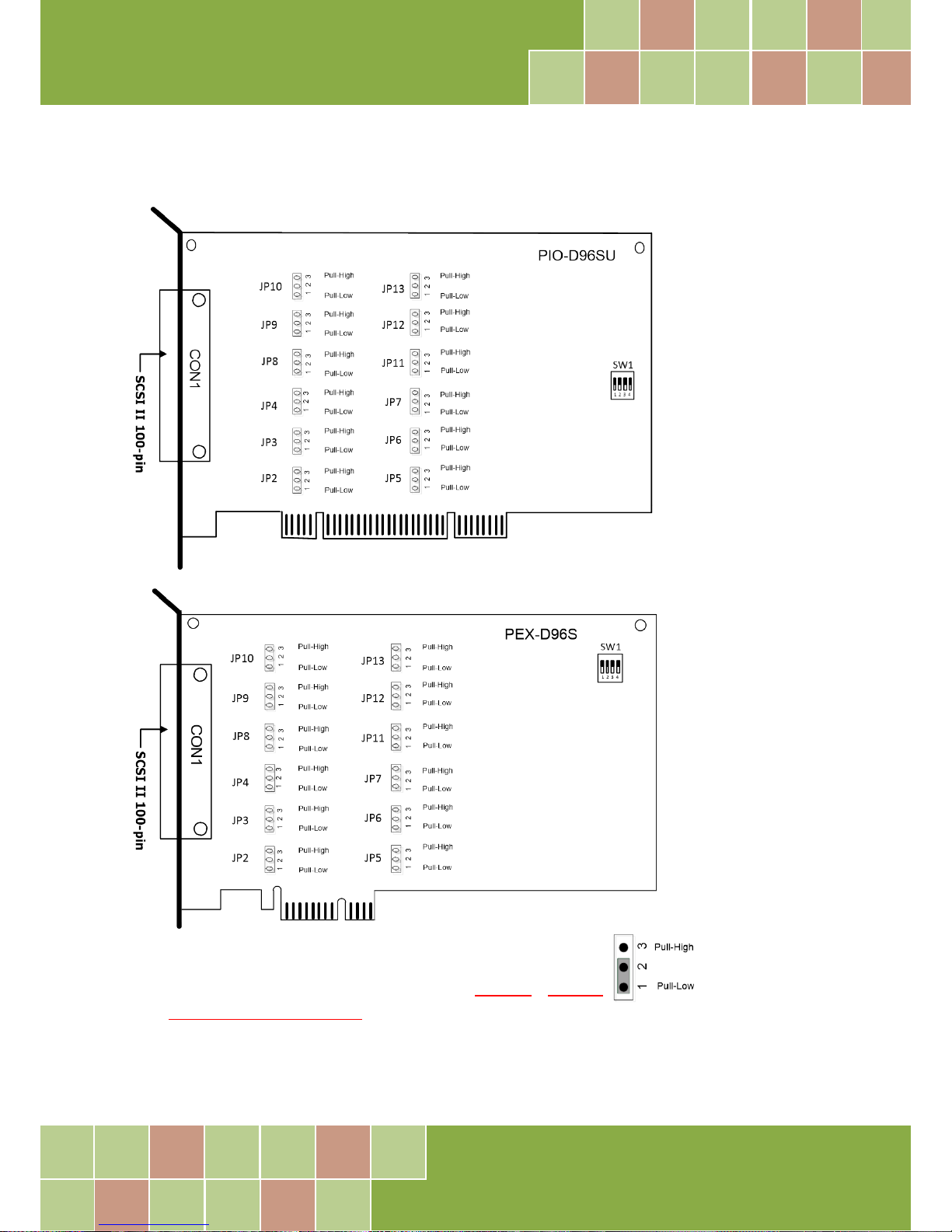
PIO-D96SU/PEX-D96S:
Note:
The JPx default settings: JP2/3/4/5/6/7/9/10/11/12/13 = 1-2 short = Pull-Low
refer to Section 2.2 “I/O Port Location” for more detailed about DI pull-high/low information.
Page 10
PIO-D96 Series Card
96-channel DIO Board
User Manual, Ve r. 2.3, Jun. 2018, PMH-008-23 Page: 9
2.2 I/O Port Location
There are twelve 8-bit I/O ports in the PIO-D96 series card. Each I/O port can be programmed as a
DI or DO port. When the PC is first powered-on or reset all the ports are configured as DI ports.
These DI ports can be selected to either pull-high or pull-low via placement of the JP2 to JP13
jumpers. These I/O port locations are given as follows:
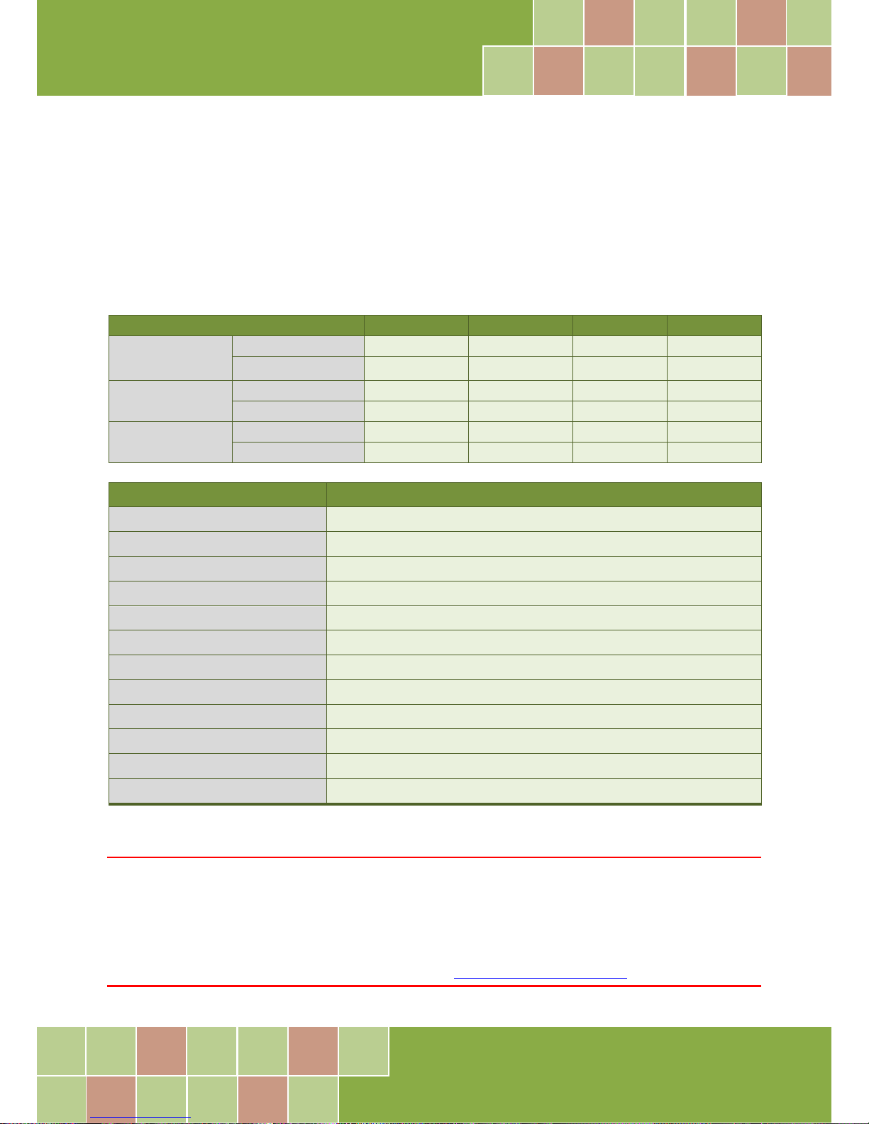
Connector of PIO-D96U (Rev 4.0 or above)
CON1
CN1
CN2
CN3
PA0 ~ PA7
Port
Port0
Port3
Port6
Port9
Pull-high/Low
JP2
JP5
JP8
PJ11
PB0 ~ PB7
Port
Port1
Port4
Port7
Port10
Pull-high/Low
JP3
JP6
JP9
JP12
PC0 ~ PC7
Port
Port2
Port5
Port8
Port11
Pull-high/Low
JP4
JP7
JP10
JP13
Connector of PIO-D96SU/PEX-D96S CON1
PA0 ~ PA7
Port0 (pull-high/low by JP2)
PB0 ~ PB7
Port1 (pull-high/low by JP3)
PC0 ~ PC7
Port2 (pull-high/low by JP4)
PA10 ~ PA17
Port3 (pull-high/low by JP5)
PB10 ~ PB17
Port4 (pull-high/low by JP6)
PC10 ~ PC17
Port5 (pull-high/low by JP7)
PA20 ~ PA27
Port6 (pull-high/low by JP8)
PB20 ~ PB27
Port7 (pull-high/low by JP9)
PC20 ~ PC27
Port8 (pull-high/low by JP10)
PA30 ~ PA37
Port9 (pull-high/low by JP11)
PB30 ~ PB37
Port10 (pull-high/low by JP12)
PC30 ~ PC37
Port11 (pull-high/low by JP13)
Note:
1. This board is a bi-directional I/O design with default DI mode when power on.
Before switching to DO mode, the DI pull-high jumper setting may activate active-high DO devices (e.g.,
DB-24R / 24PR / 24C), or the pull-low setting may activate active-low DO devices.
Please have a appropriate jumper setting depending on the characteristics of your external device.
2. Each PC0 can be used as an interrupt signal source. Refer to Section 2.7 “Interrupt Operation” for more information.
Page 11
PIO-D96 Series Card
96-channel DIO Board
User Manual, Ve r. 2.3, Jun. 2018, PMH-008-23 Page: 10
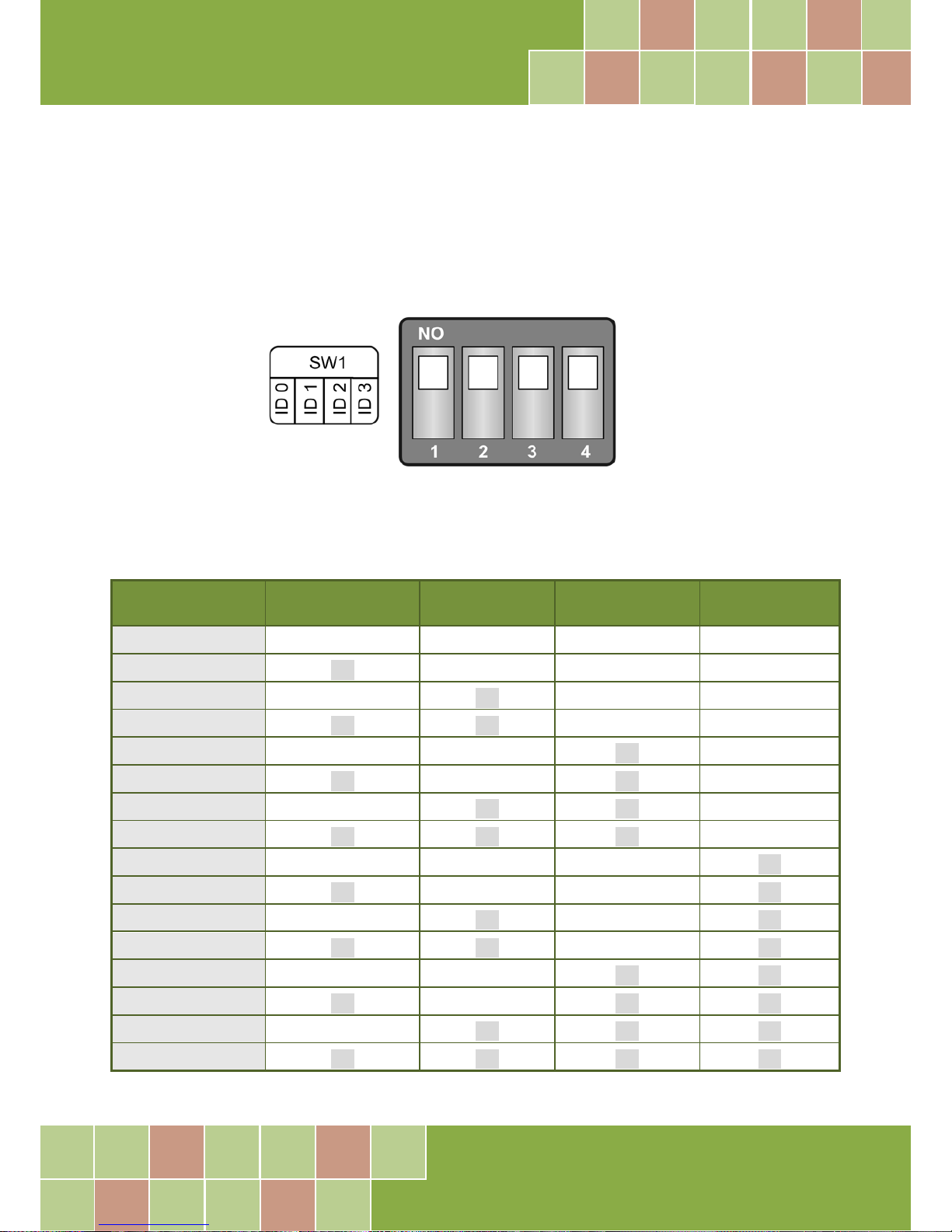
2.3 Card ID Switch
The PIO-D96U/D96SU and PEX-D96S has a Card ID switch (SW1) with which users can recognize the
board by the ID via software when using two or more PIO-D96U/D96SU and PEX-D96S cards in one
computer. The default Card ID is 0x0. For detailed information about the SW1 Card ID settings, refer
to Table 2.4.
(Default Settings)
Table 2.1 (*) Default Settings; OFF 1; ON 0
Card ID (Hex)
1
ID0
2
ID1 3 ID2 4 ID3
(*)
0x0
ON
ON
ON
ON
0x1
OFF
ON
ON
ON
0x2
ON
OFF
ON
ON
0x3
OFF
OFF
ON
ON
0x4
ON
ON
OFF
ON
0x5
OFF
ON
OFF
ON
0x6
ON
OFF
OFF
ON
0x7
OFF
OFF
OFF
ON
0x8
ON
ON
ON
OFF
0x9
OFF
ON
ON
OFF
0xA
ON
OFF
ON
OFF
0xB
OFF
OFF
ON
OFF
0xC
ON
ON
OFF
OFF
0xD
OFF
ON
OFF
OFF
0xE
ON
OFF
OFF
OFF
0xF
OFF
OFF
OFF
OFF
Page 12
PIO-D96 Series Card
96-channel DIO Board
User Manual, Ve r. 2.3, Jun. 2018, PMH-008-23 Page: 11
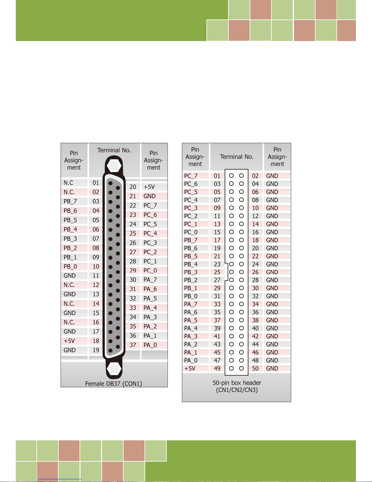
2.4 Pin Assignments
2.4.1 PIO-D96 and PIO-D96U
CON1: 37-pin D-type female connector (for Port0, Port1, Port2).
CN1/CN2/CN3: 50-pin flat-cable connector (for Port3 to Port11).
Figure 2-1
Page 13
PIO-D96 Series Card
96-channel DIO Board
User Manual, Ve r. 2.3, Jun. 2018, PMH-008-23 Page: 12
2.4.2 PIO-D96SU and PEX-D96S
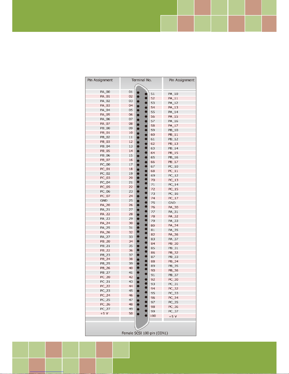
CON1: 100-pin SCSI II connector (for Port0 to Port11).
Figure 2-2
Page 14
PIO-D96 Series Card
96-channel DIO Board
User Manual, Ve r. 2.3, Jun. 2018, PMH-008-23 Page: 13
2.5 Enable I/O Operation
When the PC is first turned on, all operations involved with Digital I/O channels are disabled. Note
that the Digital I/O channel of each port is enabled or disabled by the RESET\ signal, refer to Section
6.3.1 “REST\ Control Register” for more information related to this. The power-on states for all
DI/DO ports are given as follows:
DI/DO operations for each port are disabled.
DI/DO ports are all configured as Digital Input ports.
DO latch register outputs are all high impedance. (Refer to Section 2.6 “DI/DO Architecture”)
The user has to perform some initialization before using these Digital I/O ports. The recommended
steps are given below:
Step 1: Find the address-mapping for PIO/PISO cards. (Refer to Section 6.1 “How to Find the I/O
Address”)
Step 2: Enable all Digital I/O operations. (Refer to Section 6.3.1 “RESET\ Control Register”).
Step 3: Configure the first three ports to their expected DI/DO state and send their initial values to
every DO port (Refer to Section 6.3.7 “I/O Selection Control Register”)
Step 4: Configure the other three ports to their expected DI/DO states and send their initial values
to every DO port (Refer to Section 6.3.7 “I/O Selection Control Register”)
Note:
For more information on the initial procedure for Digital I/O ports, refer to the DIO demo program.
Page 15
PIO-D96 Series Card
96-channel DIO Board
User Manual, Ve r. 2.3, Jun. 2018, PMH-008-23 Page: 14
2.6 DI/DO Architecture
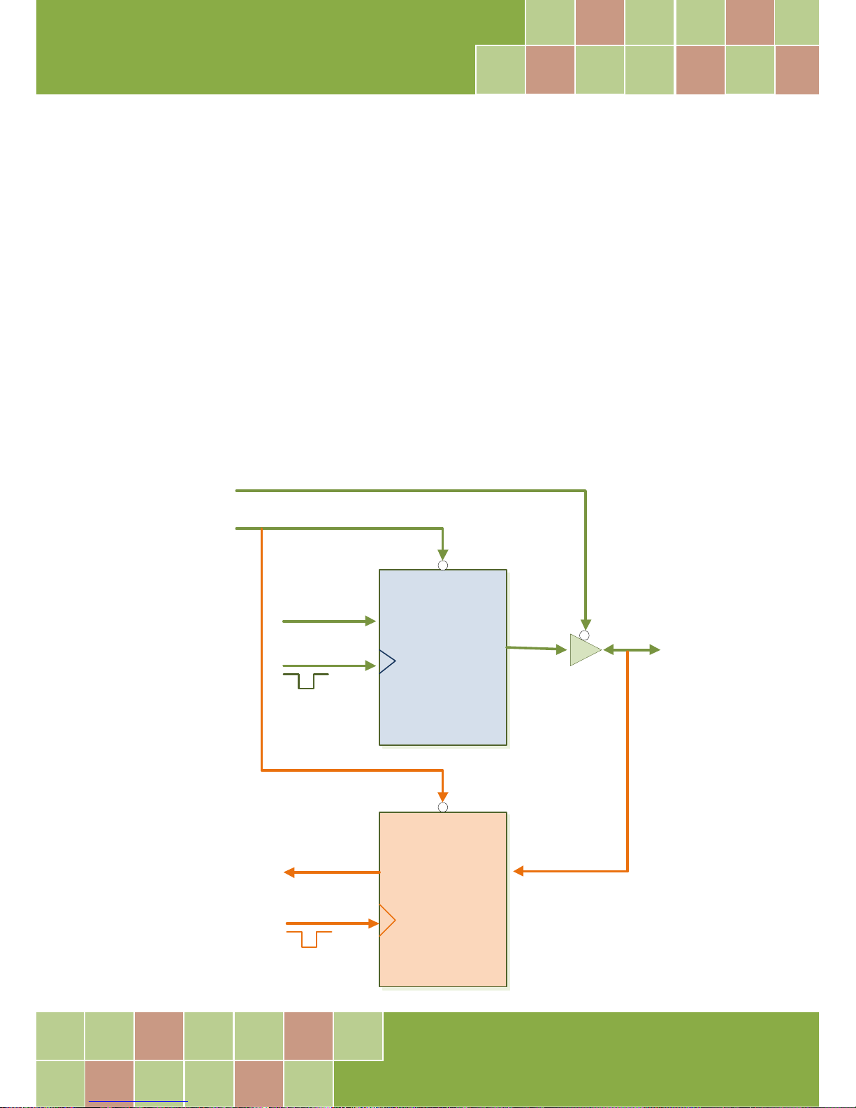
The Digital I/O control architecture for the PIO-D96 series card is demonstrated in the figure below.
The operation method used for the control signal is presented below.
RESET\ is in the Low-state all DI/DO operation is disabled
RESET\ is in the High-state all DI/DO operation is enabled.
If DI/DO is configured as a DI port DI= external input signal
If DI/DO is configured as a DO port DI = read back DO
If the DI/DO is configured as a DI port sending data to a Digital input port will only change the DO
latch register. The latched data will be output when the port is configured as digital output and is
activated right away.
Disable\
Input
Latch
Clock Input
I/O Select (Section 6.3.7)
RESET\ (Section 6.3.1)
DI/DO
Data
Section 6.3.9
Disable
Buffer
Input
Clock Input
Data
Section 6.3.9
Page 16

PIO-D96 Series Card
96-channel DIO Board
User Manual, Ve r. 2.3, Jun. 2018, PMH-008-23 Page: 15
2.7 Interrupt Operation
The P2C0, P5C0, P8C0 and P11C0 can be used as interrupt signal source. Refer to Section 2.1 “Board
Layout” and Section 2.4 “Pin Assignments” for P2C0/P5C0/P8C0/P11C0 location. The interrupt of
PIO-D96 series card is level-trigger and Active_High. The interrupt signal can be programmable as
inverted or non-inverted. The procedures for how to configure the interrupt signal source are given
as follows:
1. Make sure the initial level is high or Low from the signal source.
2. If the initial state is High, please select the inverted setting for interrupt signal source (Section
6.3.6 “Interrupt Polarity Register”). If the initial state is Low, please select the non-inverted
setting for interrupt signal source (Section 6.3.6 “Interrupt Polarity Register”)
3. Enable the interrupt function (Section 6.3.4 “INT Mask Control Register”)
4. If the interrupt signal is active, the interrupt service routine will be started up.
Note that DEMO3.C and DEMO4.C are demo programs for a single interrupt source and DEMO5.C is
the demo program for four interrupt sources in the DOS operating system. If only one interrupt
signal source is used, the interrupt service routine does not need to identify the interrupt source.
(Refer to DEMO3.C and DEMO4.C). However, if there are more than one interrupt source, the
interrupt service routine has to identify the active signals in the following manner: (refer to
DEMO5.C)
1. Read the new status of the interrupt signal sources.
2. Compare the new status with the old status to identify the active signals.
3. If P2C0 is active, service P2C0 and non-inverter/inverted the P2C0 signal.
4. If P5C0 is active, service P5C0 and non-inverted/inverted the P5C0 signal.
5. If P8C0 is active, service P8C0 and non-inverted/inverted the P8C0 signal.
6. If P11C0 is active, service P11C0 and non-inverted/inverted the P11C0 signal.
7. Update the interrupt status.
Note
If the interrupt signal is too short, the new status may be the same as the old status. So the interrupt signal must be held
active until the interrupt service routine has been executed. This hold time is different for differing operating systems. The
hold time can be as short as a micro-second or as long as 1 second. In general, 20 ms is enough for all O.S.
Page 17
PIO-D96 Series Card
96-channel DIO Board
User Manual, Ve r. 2.3, Jun. 2018, PMH-008-23 Page: 16
3. Hardware Installation
Note:
It is recommended that the driver is installed before installing the hardware as the computer may need to be
restarted once the driver is installed in certain operating systems, such as Windows 2000 or Windows XP, etc.
Installing the driver first helps reduce the time required for installation and restarting the computer.
To install your PIO-D96 series card, follow the procedure described below:
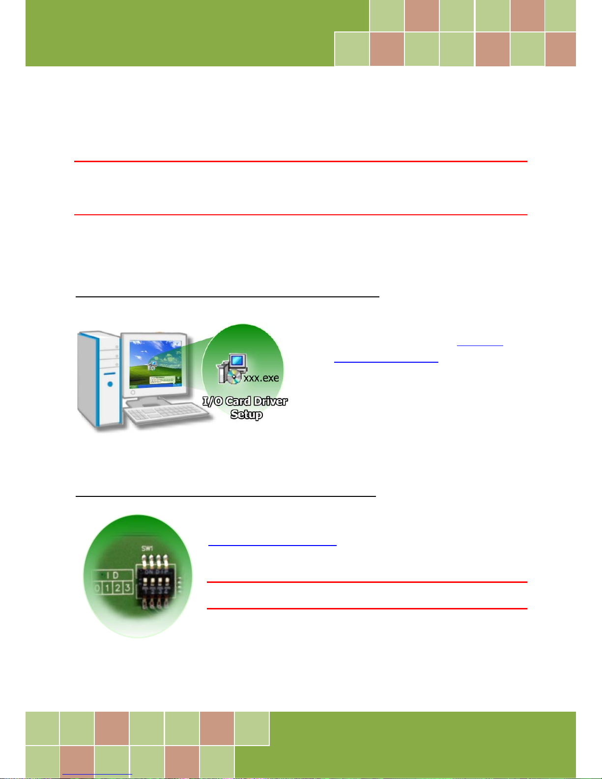
Step 1: Install the driver for your board on Host computer.
For detailed information about the driver
installation, please refer to Chapter 4
“Software Installation”.
Step 2: Configure the Card ID using the DIP Switch (SW1).
For detailed information about the card ID (SW1), please refer to
Section 2.3 “Card ID Switch”.
Note
The Card ID function is only supported by the PIO-D96U/D96SU and PEX-D96S.
Page 18
PIO-D96 Series Card
96-channel DIO Board
User Manual, Ve r. 2.3, Jun. 2018, PMH-008-23 Page: 17
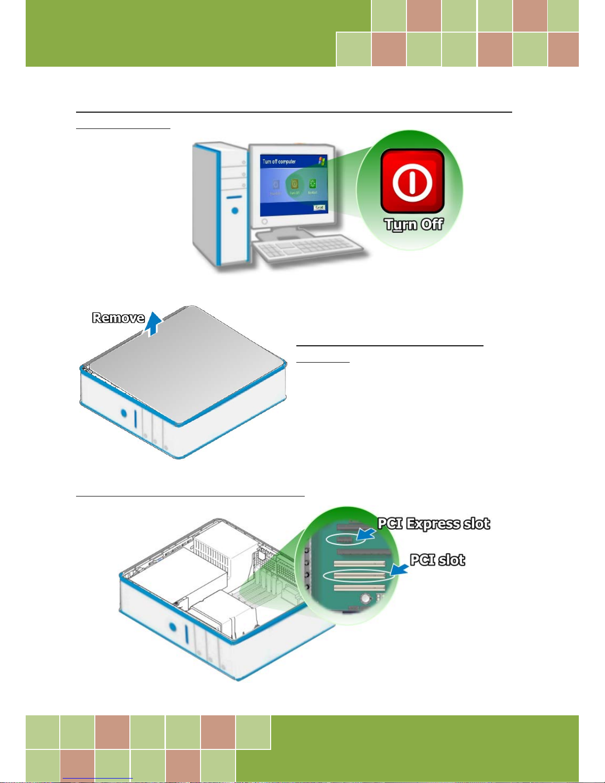
Step 3: Shut down and switch off the power to the computer, and then disconnect
the power supply.
Step 4: Remove the cover from the
computer.
Step 5: Select a vacant PCI/PCI Express slot.
Page 19
PIO-D96 Series Card
96-channel DIO Board
User Manual, Ve r. 2.3, Jun. 2018, PMH-008-23 Page: 18
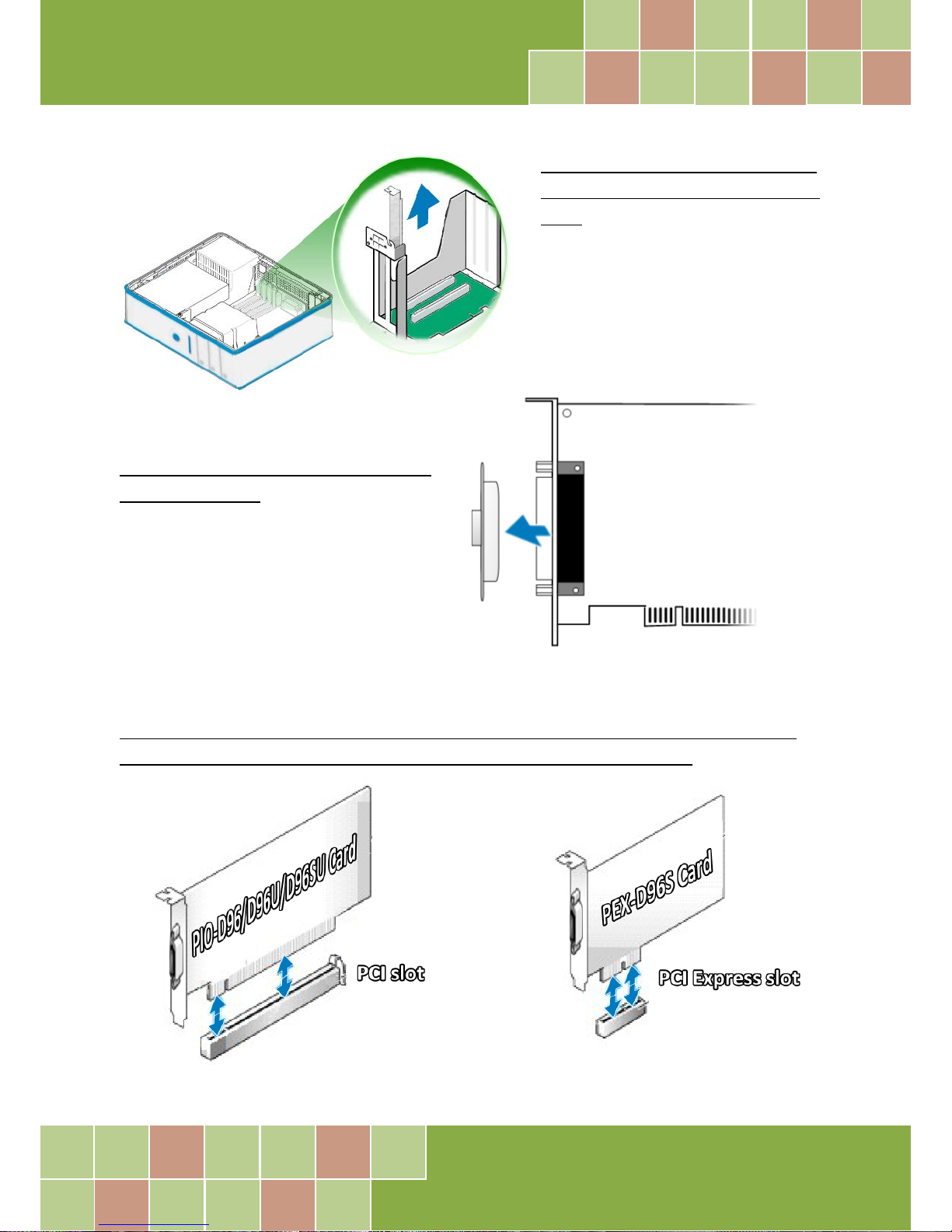
Step 6: Unscrew and remove the
PCI slot cover from the computer
case.
Step 7: Remove the connector cover
from your board.
Step 8: Carefully insert your board into the PCI/PCI Express slot by gently pushing
down on both sides of the board until it slides into the PCI connector.
Page 20
PIO-D96 Series Card
96-channel DIO Board
User Manual, Ve r. 2.3, Jun. 2018, PMH-008-23 Page: 19
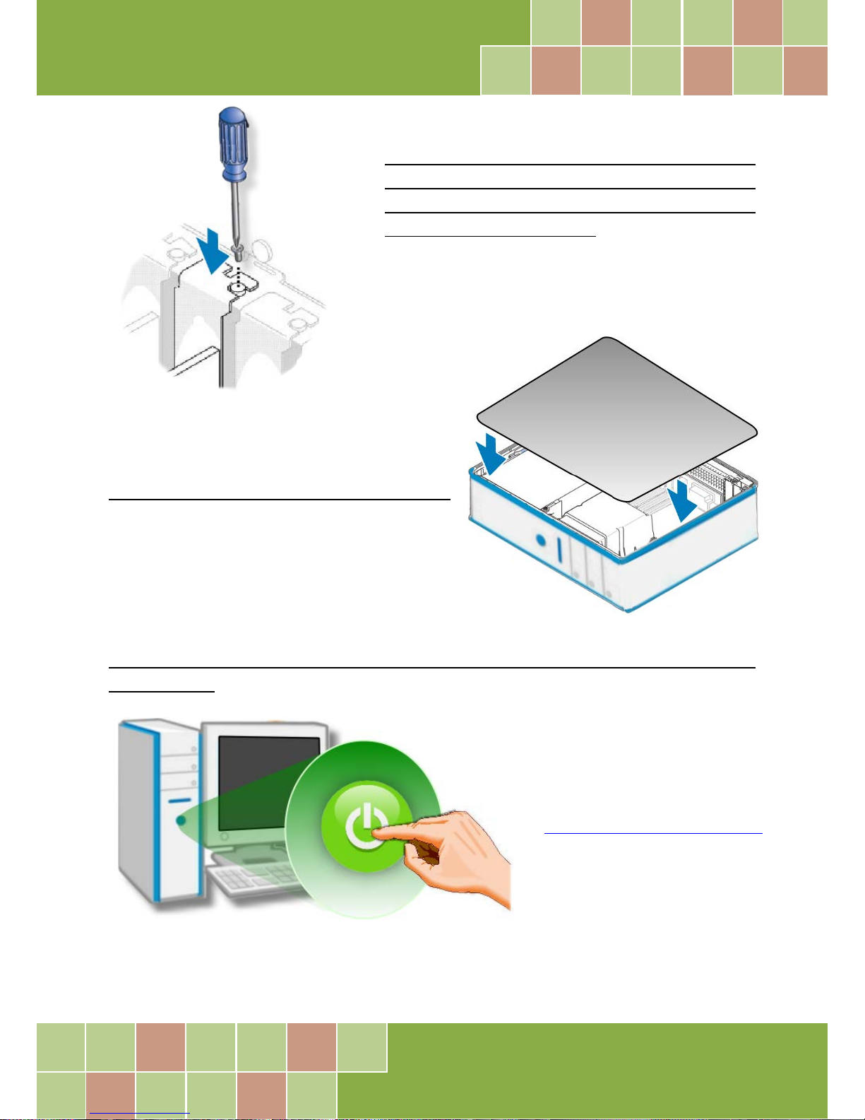
Step 9: Confirm that the board is correctly
inserted in the motherboard, and then secure
your board in place using the retaining screw
that was removed in Step 6.
Step 10: Replace the covers on the computer.
Step 11: Re-attach any cables, insert the power cord and then switch on the power to
the computer.
Once the computer reboots, follow
any message prompts that may be
displayed to complete the Plug and
Play installation procedure. Refer
to Chapter 4 “Software Installation”
for more information.
Page 21
PIO-D96 Series Card
96-channel DIO Board
User Manual, Ve r. 2.3, Jun. 2018, PMH-008-23 Page: 20
4. Software Installation
This chapter provides a detailed description of the process for installing the PIO-D96 series driver
and how to verify whether the PIO-D96 was properly installed. PIO-D96 series card can be used on
DOS, Linux and 32/64-bit XP/2003/2008/7/8/10 based systems, and the drivers are fully Plug and
Play (PnP) compliant for easy installation.
4.1 Obtaining/Installing the Driver Installer
Package
The driver installation package for PIO-D96 series board can be found on the companion CD-ROM,
or can be obtained from the ICP DAS FTP web site. Install the appropriate driver for your operating
system. The location and website addresses for the installation package are indicated below.
UniDAQ Driver/SDK (It is recommended to install this driver for new user.)
OS
Windows 2000, 32/64-bit Windows XP, 32/64-bit Windows 2003,
32/64-bit Windows Vista, 32/64-bit Windows 7, 32/64-bit Windows 2008,
32/64-bit Windows 8, 32/64-bit Windows 10
Driver Name
UniDAQ Driver/SDK (unidaq_win_setup_xxxx.exe)
CD-ROM CD:\\ NAPDOS\PCI\UniDAQ\DLL\Driver\
Web Site http://ftp.icpdas.com/pub/cd/iocard/pci/napdos/pci/unidaq/dll/driver/
Installing
Procedure
To install the UniDAQ driver, follow the procedure described below.
Step 1: Double-click the UniDAQ_Win_Setupxxx.exe icon to begin the installation
process.
Page 22
PIO-D96 Series Card
96-channel DIO Board
User Manual, Ve r. 2.3, Jun. 2018, PMH-008-23 Page: 21
Installation
Procedure
Step 2: When the “Welcome to the ICP DAS UniDAQ Driver Setup Wizard” screen is
displayed, click the “Next>” button to start the installation.
Step 3: On the “Information” screen, verify that the DAQ board is included in the list of
supported devices, then click the “Next>” button.
Step 4: On the “Select Destination Location” screen, click the “Next>” button to install the
software in the default folder, C:\ICPDAS\UniDAQ.
Step 5: On the “Select Components” screen, verify that the DAQ board is in the list of
device, and then click the “Next>” button to continue.
Step 6: On the “Select Additional Tasks” screen, click the “Next>” button to continue.
Step 7: On the “Download Information” screen, click the “Next>” button to continue.
Step 8: Once the installation has completed, click “No, I will restart my computer later”,
and then click the “Finish” button.
For more detailed information about how to install the UniDAQ driver, refer to Section 2.2
“Install UniDAQ Driver DLL” of the UniDAQ Software Manual, which can be found in
the \NAPDOS\PCI\UniDAQ\Manual\ folder on the companion CD, or can be downloaded
from: http://ftp.icpdas.com/pub/cd/iocard/pci/napdos/pci/unidaq/manual/
Page 23
PIO-D96 Series Card
96-channel DIO Board
User Manual, Ve r. 2.3, Jun. 2018, PMH-008-23 Page: 22
PIO-DIO Series Classic Driver (Recommended to install this driver for have been used
PIO-DIO series boards of regular user)
OS
Windows 95/98/ME, Windows NT, Windows 2000, 32-bit Windows XP,
32-bit Windows 2003, 32-bit Windows Vista, 32-bit Windows 7, 32-bit Windows 8, ,
32-bit Windows 10
Driver Name
PIO-DIO Series Classic Driver(PIO_DIO_Win__vxxx.exe)
CD-ROM CD:\\ NAPDOS\PCI\PIO-DIO\DLL_OCX\Driver\
Web Site
http://ftp.icpdas.com/pub/cd/iocard/pci/napdos/pci/pio-dio/dll_ocx/driver/
Installing
Procedure
Please follow the following steps to setup software:
Step 1: Double click the PIO-DIO Series Classic Driver to setup it.
Step 2: When the Setup Wizard screen is displayed, click the Next> button.
Step 3: Select the folder where the drivers are to install. The default path is
C:\DAQPro\PIO-DIO. But if you wish to install the drivers to a different location , click the
“Browse…” button and select the relevant folder and then click the Next> button.
Step 4: Click the Install button to continue.
Step 5: Select the item “No, I will restart my computer later”, press the Finish button.
For detailed information about how to install the PIO-DIO Classic Driver, refer to the
PIO-DIO Series Classic Driver DLL Software, which can be found in the
\NAPDOS\PCI\PIO-DIO\Manual\ folder on the companion CD, or can be downloaded
from: http://ftp.icpdas.com/pub/cd/iocard/pci/napdos/pci/pio-dio/manual/
Page 24
PIO-D96 Series Card
96-channel DIO Board
User Manual, Ve r. 2.3, Jun. 2018, PMH-008-23 Page: 23
4.2 PnP Driver Installation
Step 1: Correctly shut down and power off your computer and disconnect the power supply, and
then install your board into the computer. For detailed information about the hardware installation
of PIO-D96 series board, refer to Chapter 3 “Hardware Installation”.
Step 2: Power on the computer and complete the Plug and Play installation.
Note:
recent operating systems , such as Windows 7/8/10 will automatically detect the new hardware and install the
necessary drivers etc., so Steps 3 to 5 can be skipped.
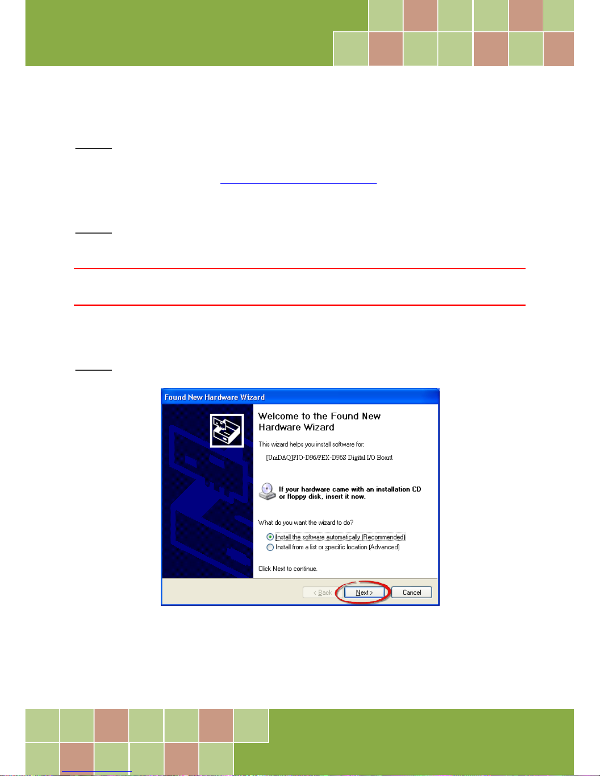
Step 3: Select “Install the software automatically [Recommended]” and click the “Next>” button.
Page 25
PIO-D96 Series Card
96-channel DIO Board
User Manual, Ve r. 2.3, Jun. 2018, PMH-008-23 Page: 24
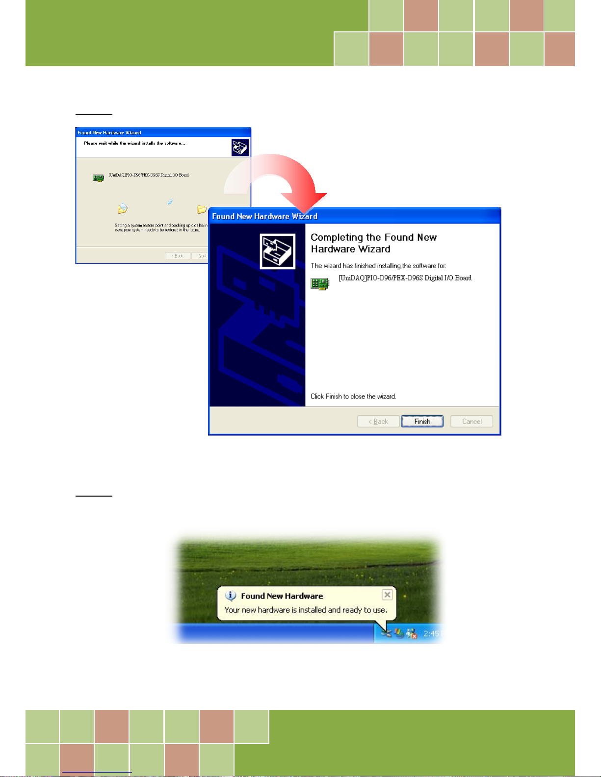
Step 4: Click the “Finish” button.
Step 5: Windows pops up “Found New Hardware” dialog box again.
Page 26
PIO-D96 Series Card
96-channel DIO Board
User Manual, Ve r. 2.3, Jun. 2018, PMH-008-23 Page: 25
4.3 Verifying the Installation
To verify that the driver was correctly installed, use the Windows Device Manager to view and
update the device drivers installed on the computer, and to ensure that the hardware is operating
correctly. The following is a description of how access the Device Manager in each of the major
versions of Windows. Refer to the appropriate description for the specific operating system to verify
the installation.
4.3.1 Accessing Windows Device Manager
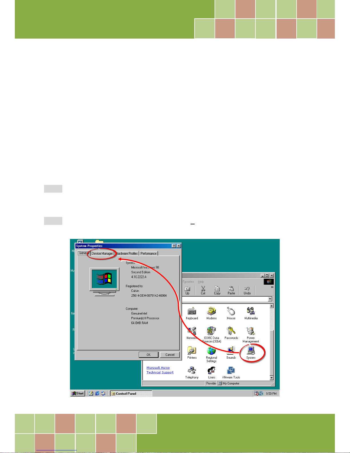
Windows 95/98/ME
Step 1: Either right-click the “My Computer” icon on the desktop and then click “Properties”, or
open the “Control Panel” and double-click the “System” icon to open the System Properties dialog
box.
Step 2: In the System Properties dialog box, click the “Device Manager” tab.
Page 27
PIO-D96 Series Card
96-channel DIO Board
User Manual, Ve r. 2.3, Jun. 2018, PMH-008-23 Page: 26
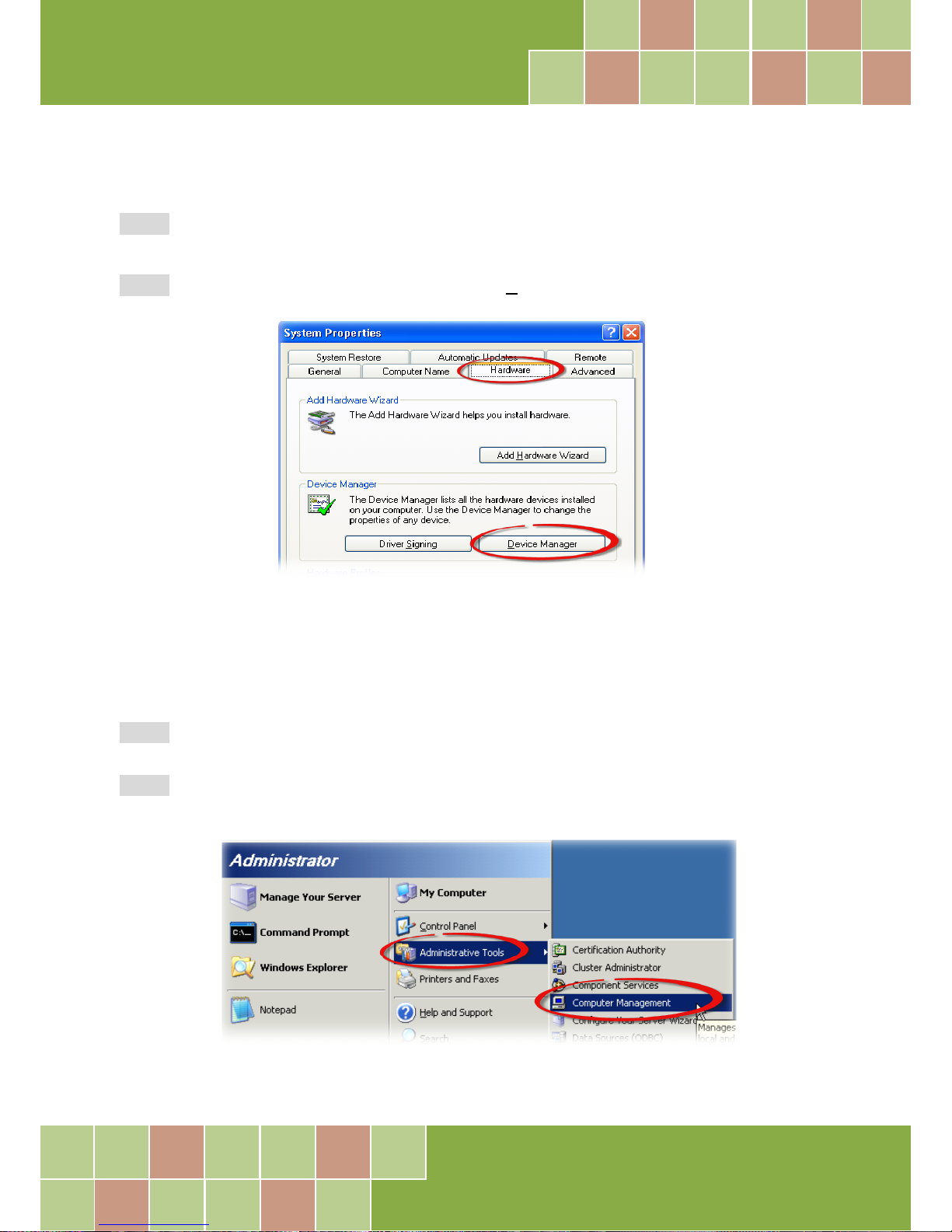
Windows 2000/XP
Step 1: Click the “Start” button and then point to “Settings” and click “Control Panel”.
Double-click the “System” icon to open the “System Properties” dialog box.
Step 2: Click the “Hardware” tab and then click the “Device Manager” button.
Windows Server 2003
Step 1: Click the “Start” button and point to “Administrative Tools”, and then click the “Computer
Management” option.
Step 2: Expand the “System Tools” item in the console tree, and then click “Device Manager”.
Page 28
PIO-D96 Series Card
96-channel DIO Board
User Manual, Ve r. 2.3, Jun. 2018, PMH-008-23 Page: 27
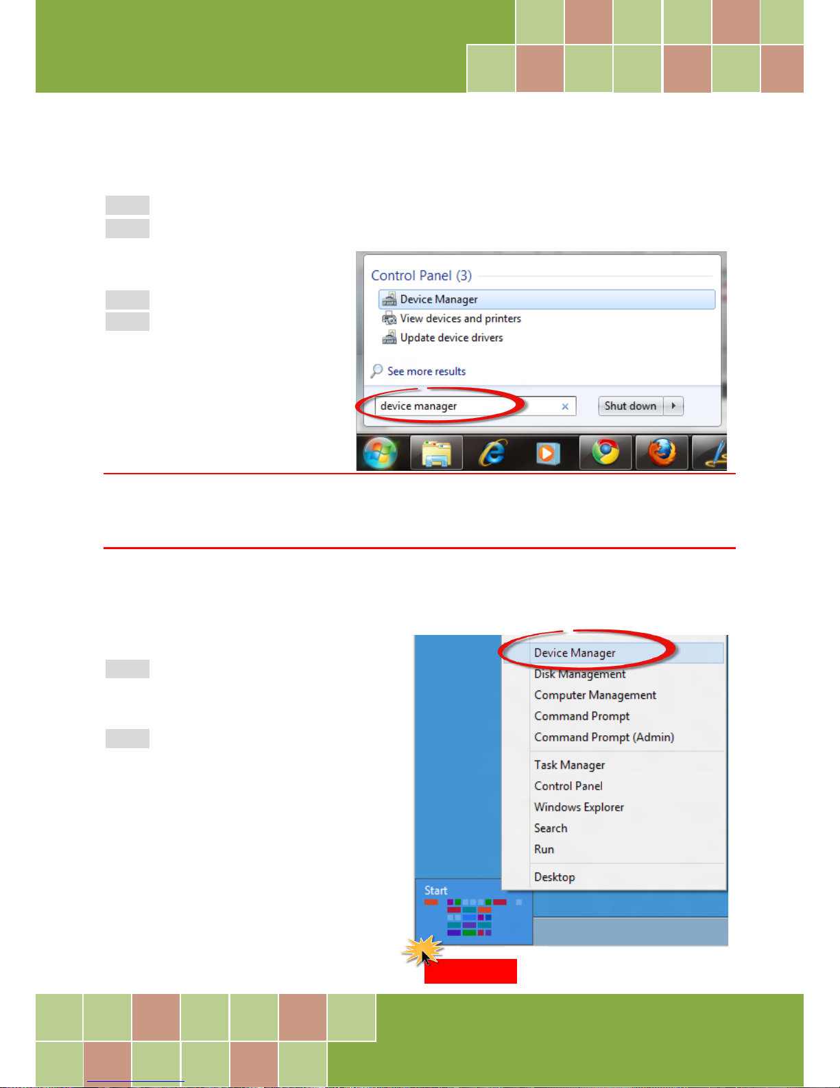
Windows 7/10
Step 1: Click the “Start” button, and then click “Control Panel”.
Step 2: Click “System and Maintenance”, and then click “Device Manager”.
Alternatively,
Step 1: Click the “Start” button.
Step 2: In the Search field, type
Device Manager and then press
Enter.
Note:
Administrator privileges are required for this operation. If you are prompted for an administrator password or
confirmation, enter the password or provide confirmation by clicking the “Yes” button in the User Account
Control message.
Windows 8
Step 1: To display the Start screen icon from
the desktop view, hover the mouse cursor
over the bottom-left corner of screen.
Step 2: Right-click the Start screen icon and
then click “Device Manager”.
Alternatively, press [Windows Key] +[X] to
open the Start Menu, and then select Device
Manager from the options list.
Right-click
Page 29
PIO-D96 Series Card
96-channel DIO Board
User Manual, Ve r. 2.3, Jun. 2018, PMH-008-23 Page: 28
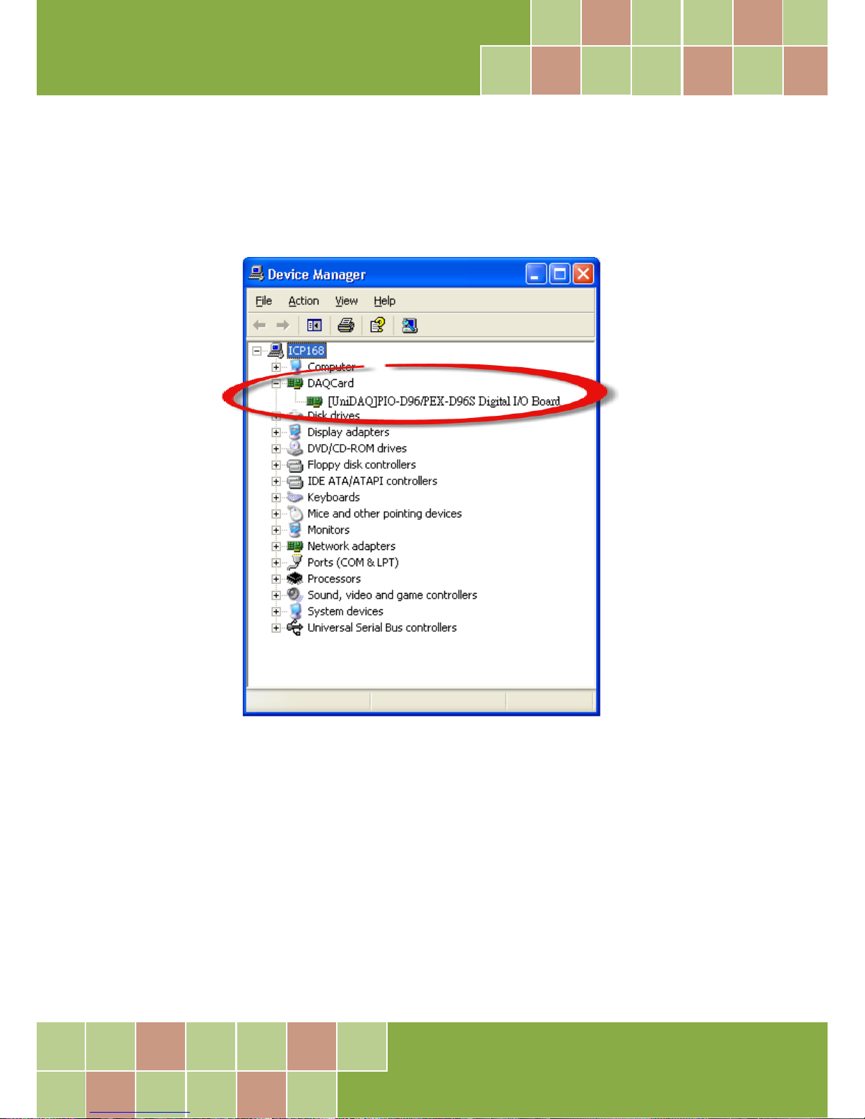
4.3.2 Check that the Installation
Check that the PIO-D96 series board is correctly listed in the Device Manager window, as illustrated
below.
Page 30
PIO-D96 Series Card
96-channel DIO Board
User Manual, Ve r. 2.3, Jun. 2018, PMH-008-23 Page: 29
5. Board Testing
This chapter provides detailed information about the “Self-Test” process, which is used to confirm
that the PIO-D96 series board is operating correctly. Before beginning the “Self-Test” process,
ensure that both the hardware and driver installation procedures are fully completed. For detailed
information about the hardware and driver installation, refer to Chapter 3 “Hardware Installation”
and Chapter 4 “Software Installation”.
5.1 Self-Test Wiring
5.1.1 PIO-D96/D96U
Before beginning the “Self-Test ” procedure, ensure that the following items are available:
A CA-3710 Cable
(Optional, Website: http://www.icpdas.com/products/Accessories/cable/cable_selection.htm)
A DN-37 Terminal Board
(Optional, Website:
http://www.icpdas.com/root/product/solutions/pc_based_io_board/daughter_boards/dn-37.html)
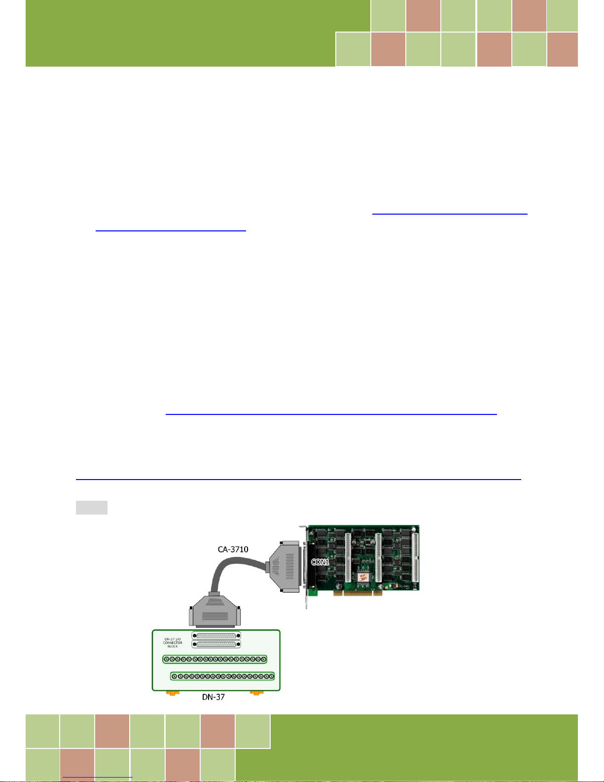
Step 1: Connect the DN-37 to the CN1 connector on your board using the CA-3710 cable.
PIO-D96/D96U
Page 31
PIO-D96 Series Card
96-channel DIO Board
User Manual, Ve r. 2.3, Jun. 2018, PMH-008-23 Page: 30
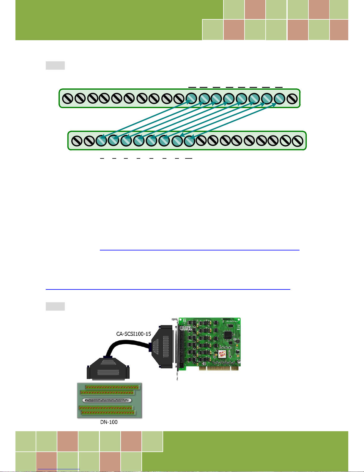
Step 2: Connect the Port0 (PA0 ~ PA7) with Port1 (PB0 ~ PB7).
5.1.2 PIO-D96SU/PEX-D96S
Before beginning the “Self-Test ” procedure, ensure that the following items are available:
A CA-SCSI100-15 Cable
(Optional, Website: http://www.icpdas.com/products/Accessories/cable/cable_selection.htm)
A DN-100 Terminal Board
(Optional, Website:
http://www.icpdas.com/root/product/solutions/pc_based_io_board/daughter_boards/dn-100.html
)
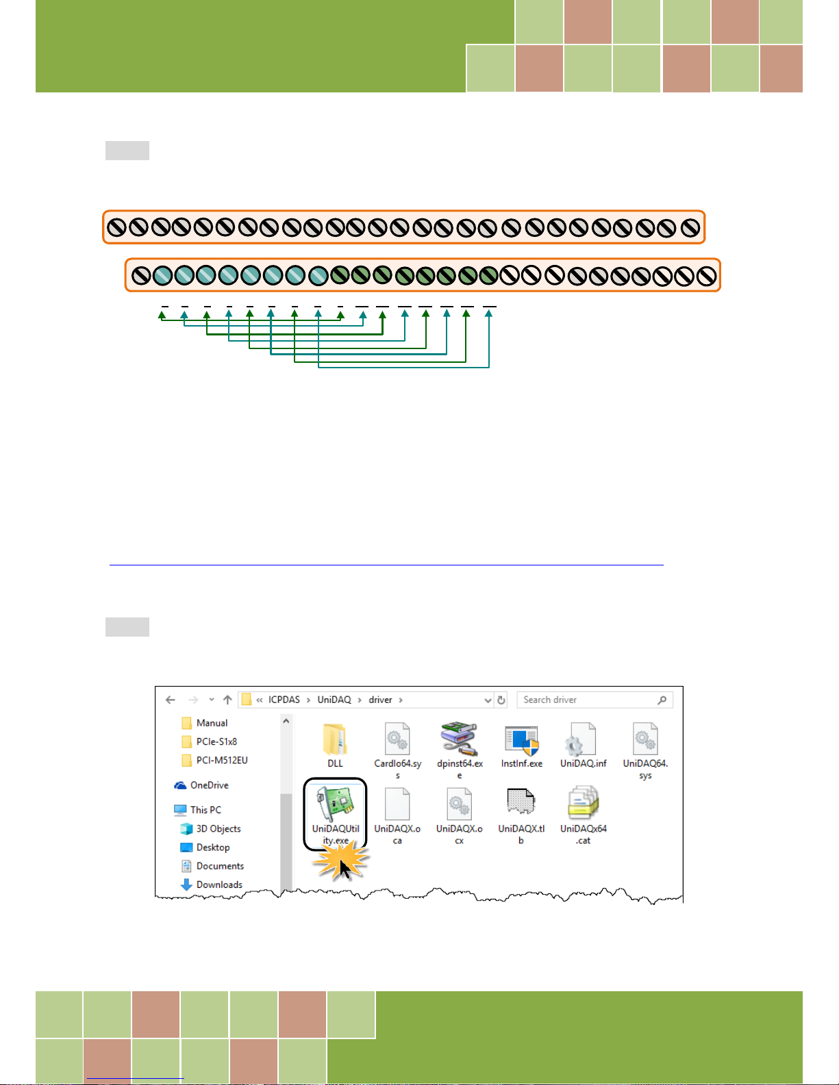
Step 1: Connect the DN-100 to the CON1 connector on your board using the CA-SCSI100-15 cable.
1 3 4
5 6
7
8 9
10
11 13 14 15 16 17 18 19
20 21 22 23 24 25 26 27 28
29
30
31
32 33
34 35
36 37
122
PIO-D96S
PEX-D96S
Page 32
PIO-D96 Series Card
96-channel DIO Board
User Manual, Ve r. 2.3, Jun. 2018, PMH-008-23 Page: 31
Step 2: Connect the Port0 (PA00 ~ PA07) with Port1 (PB00 ~ PB07).
5.2 Launch the Test Program
The following example use UniDAQ driver to perform self-test. If you install the PIO-DIO series
classic driver, refer to Quick Start Guide of the PIO-D96 series
(http://ftp.icpdas.com/pub/cd/iocard/pci/napdos/pci/pio-dio/manual/quickstart/classic/)
to execute the self-test.
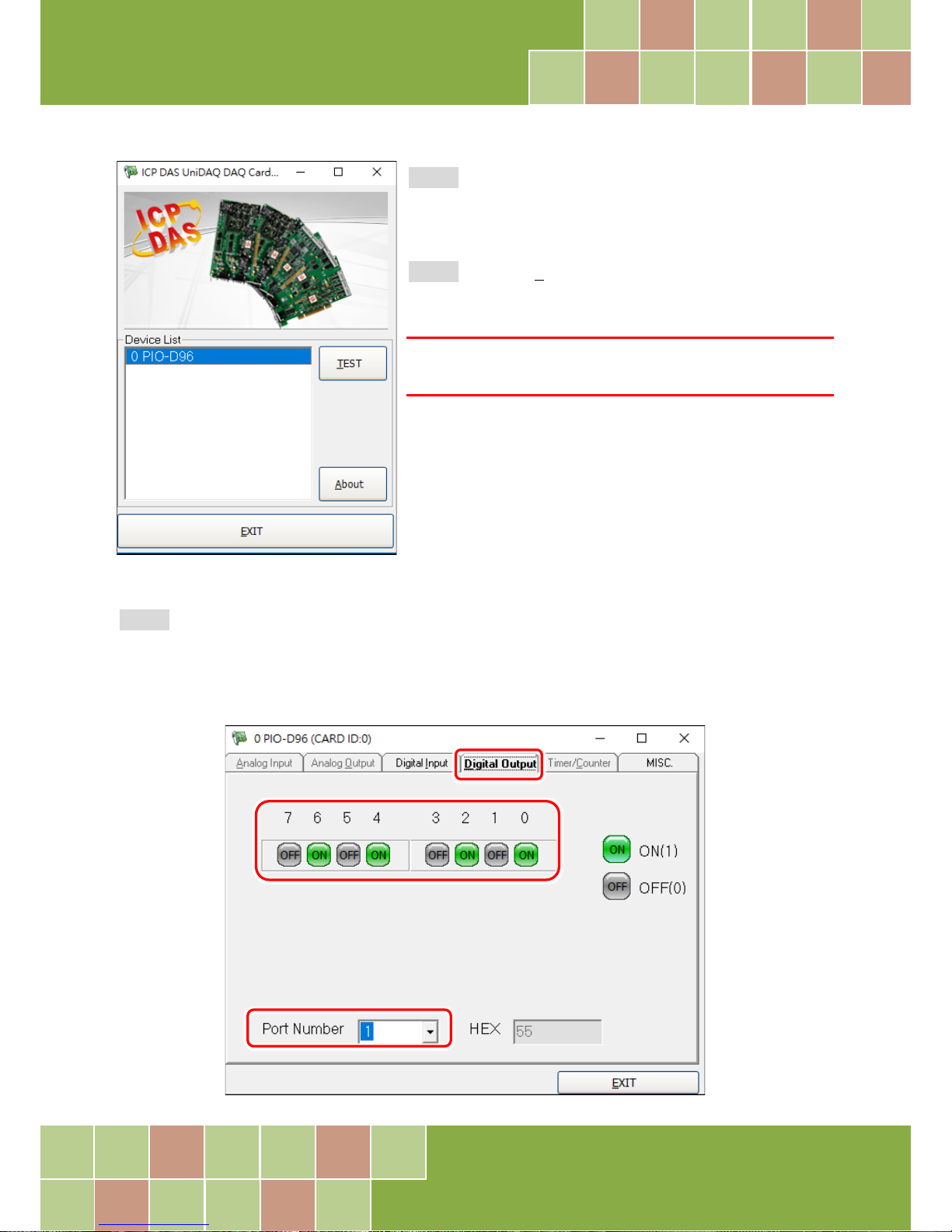
Step 1: Double-click the UniDAQ Utility software. The UniDAQ Utility will be placed in the default
path “C:\ICPDAS\UniDAQ\Driver” after completing installation.
1 3 4 5
6
7 8
9
10
11 13 14 15 16 17 18 19
FG 51
52 53 54 55 56 57 58 59
60
61
62 63
64 65
66 67
122
FG 20 21 22 23 24 25 NG
68 69 70 71 72 73 74 75 NG
Page 33
PIO-D96 Series Card
96-channel DIO Board
User Manual, Ve r. 2.3, Jun. 2018, PMH-008-23 Page: 32
Step 2: Confirm that your board has been successfully
installed in the Host system. Note that the device number
starts from 0.
Step 3: Click the “TEST” button to start the test.
Note:
The PEX-D96S, PIO-D96SU and PIO-D96U software is fully
compatible with the PIO-D96 series software.
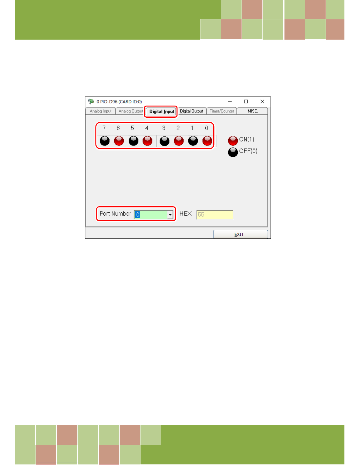
Step 4: Check the results of the Digital Input and Digital Output functions test.
1. Click the “Digital Output” tab.
2. Select “Port 1” from the “Port Number” drop-down menu.
3. Check the checkboxes for channels 0, 2, 4 and 6.
Page 34
PIO-D96 Series Card
96-channel DIO Board
User Manual, Ve r. 2.3, Jun. 2018, PMH-008-23 Page: 33
4. Click the “Digital Input” tab.
5. Select “Port 0” from the “Port Number” drop-down menu.
6. The DI indicators will turn red when the corresponding DO channels 0, 2, 4 and 6 are ON.
Page 35
PIO-D96 Series Card
96-channel DIO Board
User Manual, Ve r. 2.3, Jun. 2018, PMH-008-23 Page: 34
6. I/O Control Register
6.1 How to Find the I/O Address
During the power-on stage, the Plug and Play BIOS will assign an appropriate I/O address to each
PIO-D96 series card installed in the system. Each board includes four fixed ID numbers that are used
to identify the board, and are indicated below:
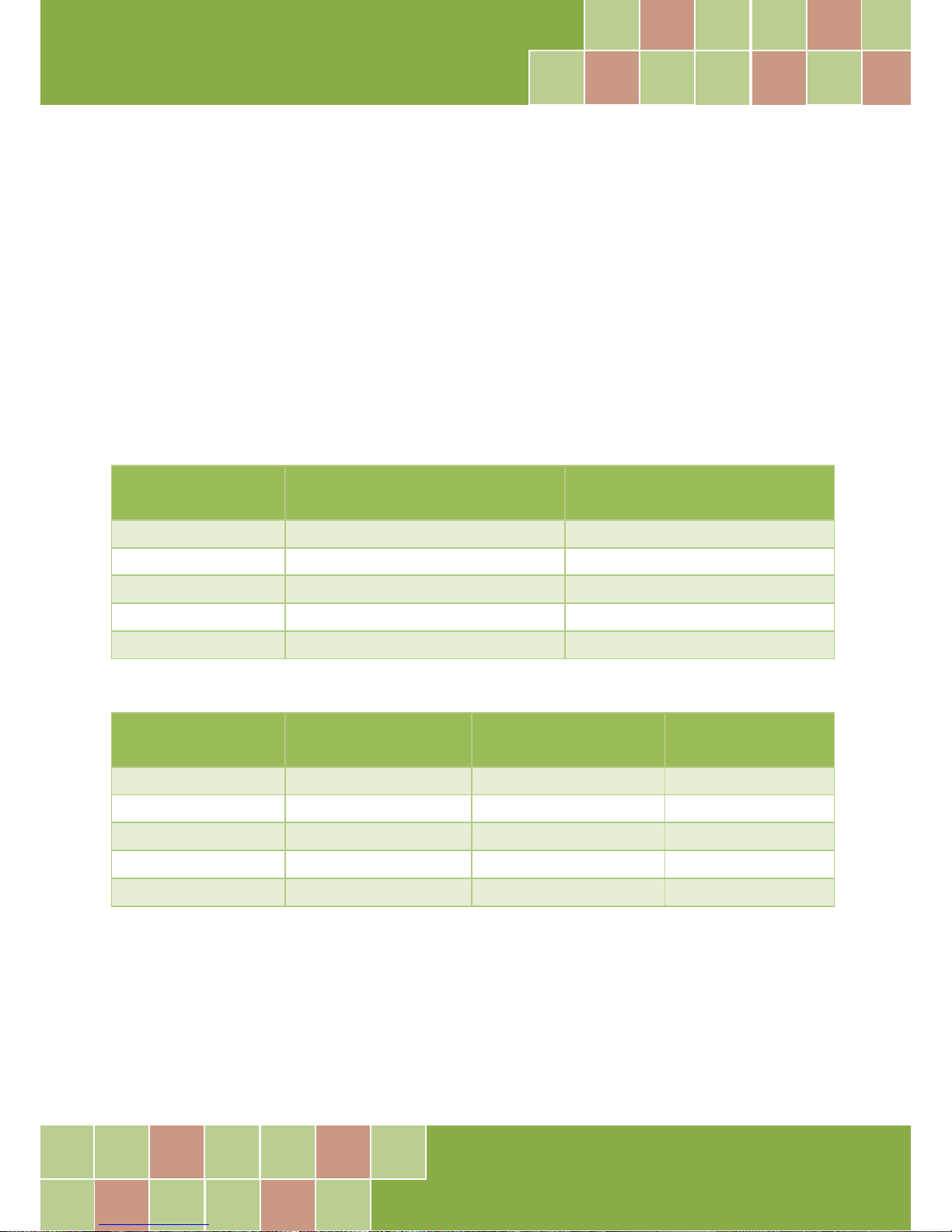
Table 6-1:
PIO-D96
(Rev 1.0 ~ 3.0)
PIO-D96
(Rev 4.0 or above)
Vendor ID
0xE159
0xE159
Device ID
0x0002
0x0001
Sub-Vendor ID
0x80
0x5880
Sub-Device ID
0x01
0x01
Sub-Aux ID
0x10
0x10
Table 6-2:
PIO-D96U
(Rev 1.0 or above)
PIO-D96SU
(Rev 1.0 or above)
PEX-D96S
(Rev 1.0 or above)
Vendor ID
0xE159
0xE159
0xE159
Device ID
0x0001
0x0001
0x0001
Sub-Vendor ID
0x5880
0x1880
0x1880
Sub-Device ID
0x01
0x01
0x01
Sub-Aux ID
0x10
0x10
0x10
Page 36
PIO-D96 Series Card
96-channel DIO Board
User Manual, Ve r. 2.3, Jun. 2018, PMH-008-23 Page: 35
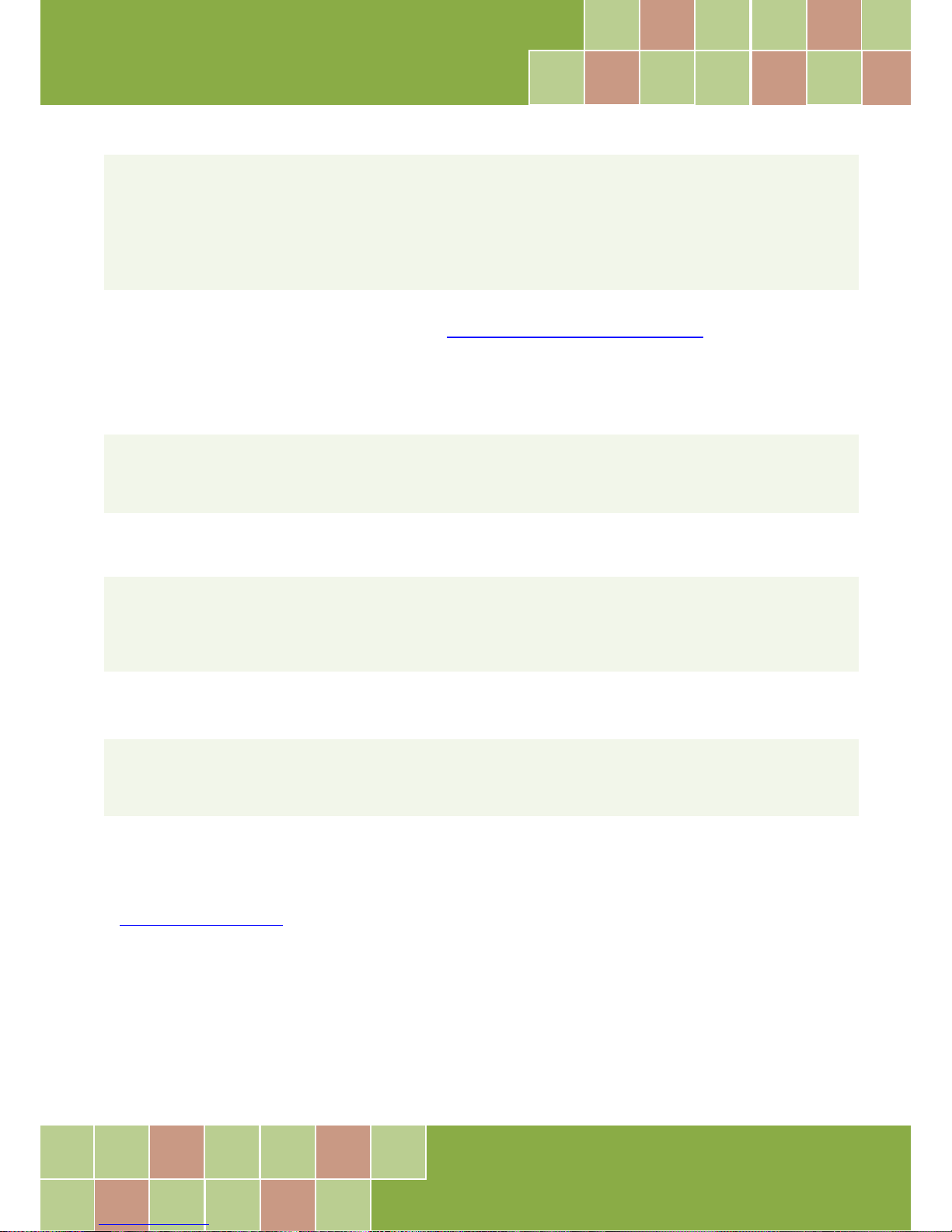
We provide all necessary functions as follows:
1. PIO_DriverInit(&wBoard, wSubVendor, wSubDevice, wSubAux)
2. PIO_GetConfigAddressSpace(wBoardNo,*wBase,*wIrq, *wSubVendor,*wSubDevice, *wSubAux,
*wSlotBus, *wSlotDevice)
3. Show_PIO_PISO(wSubVendor, wSubDevice, wSubAux)
All functions are defined in PIODIO.H. Refer to Section 6.3 “The I/O Address Map” for more
information. The important driver information is given as follows:
Allocated resource information:
• wBase : BASE address mapping in this PC
• wIrq: Allocated IRQ channel number of this board in this PC
PIO/PISO identification information:
• wSubVendor: subVendor ID of this board
• wSubDevice: subDevice ID of this board
• wSubAux: subAux ID of this board
PC’s physical slot information:
• wSlotBus: The bus number of the slot used by this board.
• wSlotDevice: The device number of the slot used by this board.
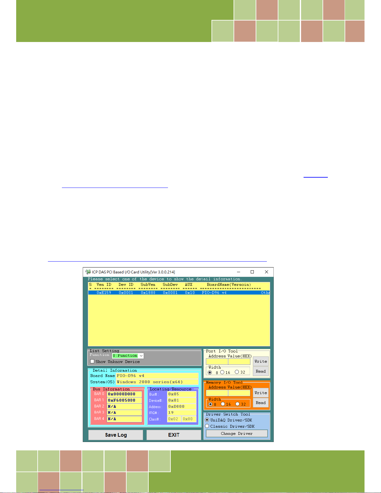
The PIO_PISO.EXE utility will detect and show all PIO/PISO cards installed in this PC. Refer to
“PIO_PISO.EXE Utility” for more information.
Page 37
PIO-D96 Series Card
96-channel DIO Board
User Manual, Ve r. 2.3, Jun. 2018, PMH-008-23 Page: 36
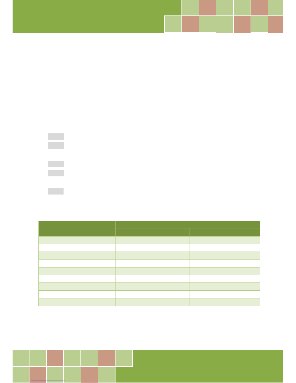
PIO_PISO.EXE Utility
The PIO_PISO.EXE utility is valid for all PIO/PISO cards. This program shows all PCI hardware ID
regarding the PIO and PISO series DAQ cards. It is useful to test if the card Plug & Play successfully
when the computer bootup. If the PIO or PISO series card does not shown in the screen correctly,
please try to use another PCI slot and try again.
The user can execute the PIO_PISO.EXE to get the following information:
List all PIO/PISO cards installed in this PC
List all resources allocated to every PIO/PISO cards
List the wSlotBus and wSlotDevice for specified PIO/PISO card identification. (refer to Section
6.2 “The Assignment of I/O Address” for more information about the assignment of I/O
Address)
For Windows OS
The PIO_PISO.EXE utility is located on the CD as below and is useful for all PIO-DIO series boards.
(CD:\NAPDOS\PCI\Utility\Win32\PIO_PISO\)
http://ftp.icpdas.com/pub/cd/iocard/pci/napdos/pci/utility/win32/pio_piso/
Page 38
PIO-D96 Series Card
96-channel DIO Board
User Manual, Ve r. 2.3, Jun. 2018, PMH-008-23 Page: 37
For DOS
The PIO_PISO.EXE for DOS is contained in:
CD:\NAPDOS\PCI\Utility\DOS\
http://ftp.icpdas.com/pub/cd/iocard/pci/napdos/pci/utility/dos/
The PIO_PISO program source is given as follows:
/* -------------------------------------------------------------- */
/* Find all PIO_PISO series cards in this PC system */
/* step 1 : plug all PIO_PISO cards into PC */
/* step 2 : run PIO_PISO.EXE */
/* ------------------------------------------------------------- */
#include "PIO.H"
WORD wBase,wIrq;
WORD wBase2,wIrq2;
int main()
{
int i,j,j1,j2,j3,j4,k,jj,dd,j11,j22,j33,j44;
WORD wBoards,wRetVal;
WORD wSubVendor,wSubDevice,wSubAux,wSlotBus,wSlotDevice;
char c;
float ok,err;
clrscr();
wRetVal=PIO_DriverInit(&wBoards,0xff,0xff,0xff); /*for PIO-PISO */
printf("\nThrer are %d PIO_PISO Cards in this PC",wBoards);
if (wBoards==0 ) exit(0);
printf("\n-----------------------------------------------------");
for(i=0; i<wBoards; i++)
{
PIO_GetConfigAddressSpace(i,&wBase,&wIrq,&wSubVendor,
&wSubDevice,&wSubAux,&wSlotBus,&wSlotDevice);
printf("\nCard_%d:wBase=%x,wIrq=%x,subID=[%x,%x,%x],
SlotID=[%x,%x]",i,wBase,wIrq,wSubVendor,wSubDevice,
wSubAux,wSlotBus,wSlotDevice);
printf(" --> ");
ShowPioPiso(wSubVendor,wSubDevice,wSubAux);
}
PIO_DriverClose();
}
Page 39
PIO-D96 Series Card
96-channel DIO Board
User Manual, Ve r. 2.3, Jun. 2018, PMH-008-23 Page: 38
6.2 The Assignment of I/O Address
The Plug and Play BIOS will assign the proper I/O address to a PIO/PISO series card. If there is only
one PIO/PISO card, the user can identify the card as card_0. If there are two PIO/PISO card s in the
system, it is very difficult to identify which board is card_0. The software driver can support a
maximum of 16 cards. Therefore, the user can install 16 PIO/PSIO series cards onto one PC system.
The methods used to find and identify card_0 and card_1 is demonstrated below.
The simplest way to identify which card is card_0 is to use wSlotBus and wSlotDevice in the
following manner:
Step 1: Remove all PIO-D96 series boards from the PC.
Step 2: Install one PIO-D96 series onto the PC’s PCI_slot1, run PIO_PISO.EXE.
Then record the “wSlotBus1” and “wSlotDevice1” information.
Step 3: Remove all PIO-D96 series boards from the PC.
Step 4: Install one PIO-D96 series into the PC’s PCI_slot2 and run PIO_PISO.EXE.
Then record the “wSlotBus2” and “wSlotDevice2” information.
Step 5: Repeat Steps(3) and (4) for every PCI_slot and record all information from “wSlotBus”
and “wSlotDevice”.
The records may look similar to the table follows:
PC’s PCI Slot
Locating/Resource
wSlotBus (Bus#)
wSlotBus (Device#)
Slot_1
0
0x07
Slot_2
0
0x08
Slot_3
0
0x09
Slot_4
0
0x0A
PCI-BRIDGE
Slot_5
1
0x0A
Slot_6
1
0x08
Slot_7
1
0x09
Slot_8
1
0x07
Table 6-3
Page 40
PIO-D96 Series Card
96-channel DIO Board
User Manual, Ve r. 2.3, Jun. 2018, PMH-008-23 Page: 39
The above procedure will record all the “wSlotBus” and “wSlotBus” information on a PC. These
values will be mapped to this PC’s physical slot and this mapping will not be changed for any
PIO/PISO cards. Therefore, this information can be used to identify the specified PIO/PISO card by
following steps:
Step1: Using the “wSlotBus” and “wSlotDevice” information from Table 6-4.
Step2: Enter the board number into PIO_GetConfigAddressSpace(…) function to get the
information for a specific card, especially the “wSlotBus” and “wSlotDevice” details.
Step3: Identify the specific PIO/PISO card by comparing the data of the “wSlotBus” and
“wSlotDevice” from Step1 and Step2.
Note:
Normally the card installed in slot 0 is card0 and the card installed in slot1 is card1 for PIO/PISO series cards.
Page 41
PIO-D96 Series Card
96-channel DIO Board
User Manual, Ve r. 2.3, Jun. 2018, PMH-008-23 Page: 40
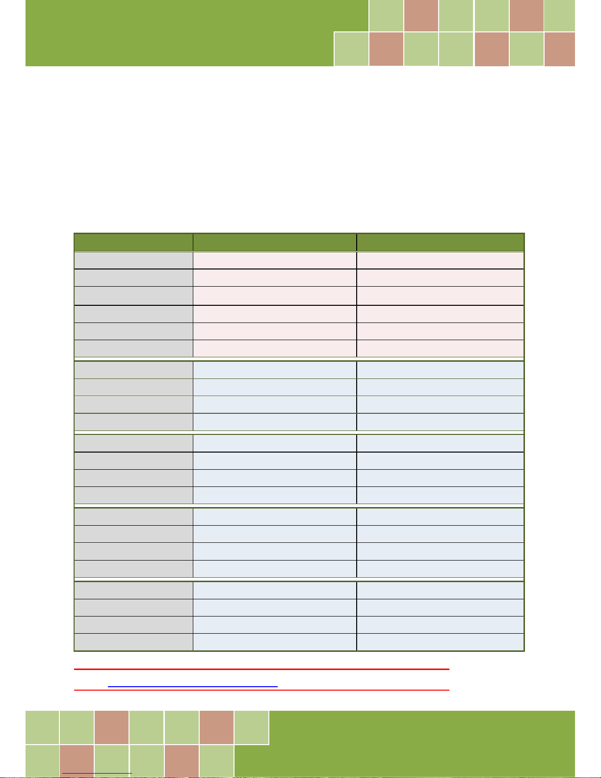
6.3 The I/O Address Map
The I/O address of the PIO/PISO series card is automatically assigned by the main board ROM BIOS.
The I/O address can also be re-assigned by the user, but it is strongly recommended that the I/O
address is not changed by user. The Plug and Play BIOS will assign an appropriate I/O address to
each PIO/PISO series card. The I/O addresses of the PIO-D96 series card are as follows, and are
based on the base address of each card.
Table 6-4:
Address Read Write
wBase+0 - RESET\ Control Register
wBase+2 Aux control register Same
wBase+3 Aux data register Same
wBase+5 INT mask control register Same
wBase+7 Aux pin status register Same
wBase+0x2a INT polarity control register Same
wBase+0xc0 Read Port0 Write Port0
wBase+0xc4 Read Port1 Write Port1
wBase+0xc8 Read Port2 Write Port2
wBase+0xcc - Port0 ~ Port2 Configuration
wBase+0xd0 Read Port3 Write Port3
wBase+0xd4 Read Port4 Write Port4
wBase+0xd8 Read Port5 Write Port5
wBase+0xdc - Port3 ~ Port5 Configuration
wBase+0xe0 Read Port6 Write Port6
wBase+0xe4 Read Port7 Write Port7
wbase+0xe8 Read Port8 Write Port8
wBase+0xec - Port6 ~ Port8 Configuration
wBase+0xf0 Read Port9 Write Port9
wBase+0xf4 Read Port10 Write Port10
wBase+0xf8 Read Port11 Write Port11
wBase+0xfc Read Card ID Port9 ~ Port11 Configuration
Note:
Refer to Section 6.1 “How to Find the I/O Address” for more information about wBase.
Page 42
PIO-D96 Series Card
96-channel DIO Board
User Manual, Ve r. 2.3, Jun. 2018, PMH-008-23 Page: 41
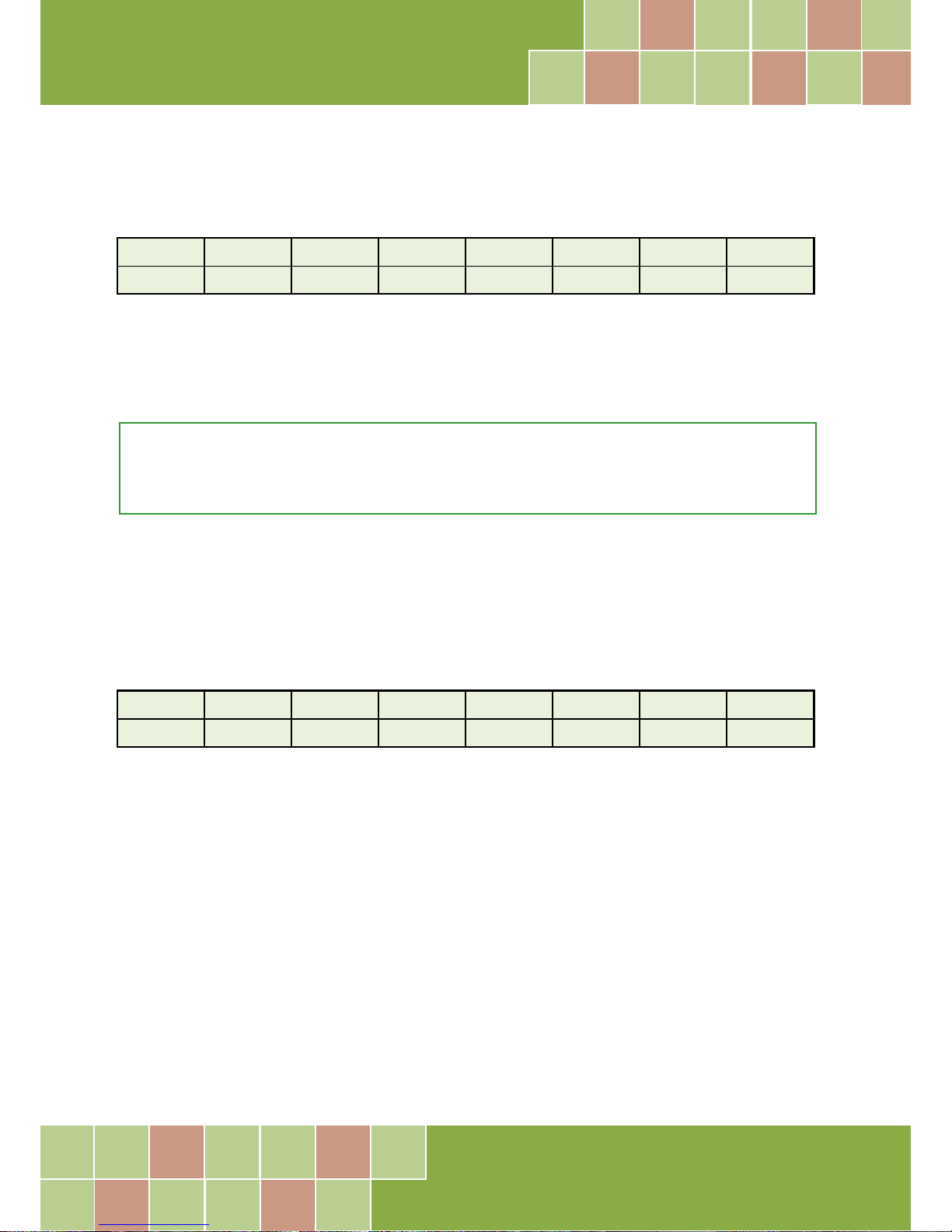
6.3.1 RESET\ Control Register
(Write): wBase+0
Bit 7 Bit 6 Bit 5 Bit 4 Bit 3 Bit 2 Bit 1 Bit 0
Reserved Reserved Reserved Reserved Reserved Reserved Reserved RESET\
When the PC’s power is first turned on, RESET\ signal is in a Low-state. This will disable all DI/O
operations. The user has to set the RESET\ signal to a High-state before any DI/O command
applications are initiated.
For example:
outportb (wBase,1); /* RESET\=High all DI/O are enable now */
outportb (wBase,0); /* RESET\=Low all DI/O are disable now */
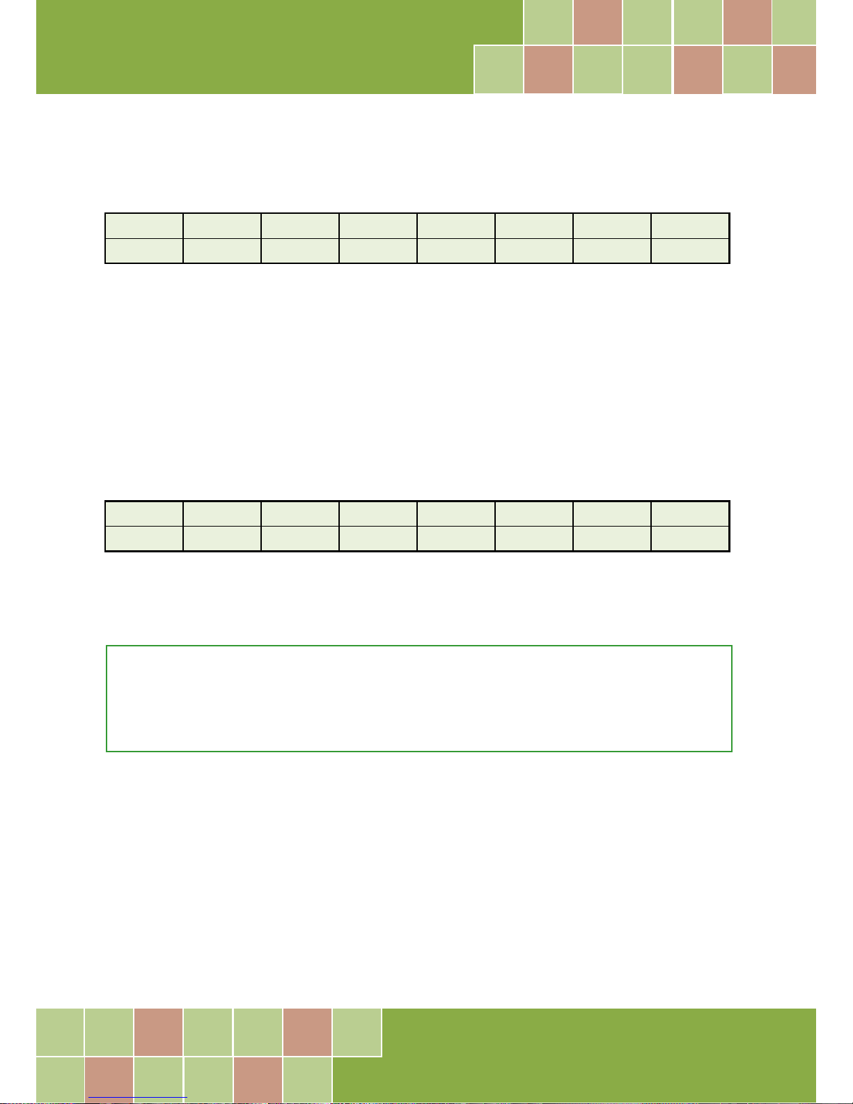
6.3.2 AUX Control Register
(Read/Write): wBase+2
Bit 7 Bit 6 Bit 5 Bit 4 Bit 3 Bit 2 Bit 1 Bit 0
Aux7 Aux6 Aux5 Aux4 Aux3 Aux2 Aux1 Aux0
Aux?=0 this Aux is used as a DI
Aux?=1 this Aux is used as a DO
When the PC is first turned on, all Aux signals are in a Low-state. All Aux are designed as DI for all
PIO/PISO series.
Page 43
PIO-D96 Series Card
96-channel DIO Board
User Manual, Ve r. 2.3, Jun. 2018, PMH-008-23 Page: 42
6.3.3 AUX Data Register
(Read/Write): wBase+3
Bit 7 Bit 6 Bit 5 Bit 4 Bit 3 Bit 2 Bit 1 Bit 0
Aux7 Aux6 Aux5 Aux4 Aux3 Aux2 Aux1 Aux0
When the Aux is used for DO, the output state is controlled by this register. This register is designed
for feature extension. Therefore, do not use this register.
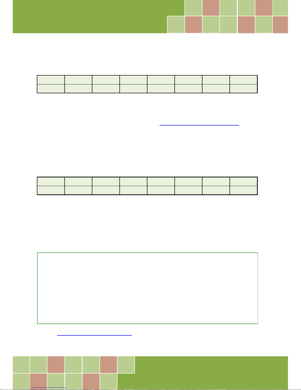
6.3.4 INT Mask Control Register
(Read/Write): wBase+5
Bit 7 Bit 6 Bit 5 Bit 4 Bit 3 Bit 2 Bit 1 Bit 0
0 0 0 0 EN3 EN2 EN1 EN0
EN0=0 Disable P2C0 of CN1 as an interrupt signal (Default).
EN0=1 Enable P2C0 of CN1 as an interrupt signal
For example:
outportb(wBase+5,0); /*Disable interrupt */
outportb(wBase+5,1); /* Enable interrupt P2C0 */
outportb(wBase+5,0x0f); /* Enable interrupt P2C0, P5C0,P8C0,P11C0 */
Page 44
PIO-D96 Series Card
96-channel DIO Board
User Manual, Ve r. 2.3, Jun. 2018, PMH-008-23 Page: 43
6.3.5 Aux Status Register
(Read/Write): wBase+7
Bit 7 Bit 6 Bit 5 Bit 4 Bit 3 Bit 2 Bit 1 Bit 0
Aux7 Aux6 Aux5 Aux4 Aux3 Aux2 Aux1 Aux0
Aux0=P2C0, Aux1=P5C0, Aux2=P8C0, Aux3=P11C0, Aux7~4=Aux-ID. Refer to DEMO5.C for more
information. The Aux 0~3 are used as interrupt source. The interrupt service routine has to read this
register to identify the interrupt source. Refer to Section 2.7 “Interrupt Operation” for more
information.
6.3.6 Interrupt Polarity Register
(Read/Write): wBase+0x2A
Bit 7 Bit 6 Bit 5 Bit 4 Bit 3 Bit 2 Bit 1 Bit 0
0 0 0 0 INV3 INV2 INV1 INV0
This register provides a function to control invert or non-invert for the interrupt signal source. A
detailed application example is given below.
INV0=1 select the non-inverted signal from P2C0
INV0=0 select the inverted signal from P2C0
For example:
outportb(wBase+0x2a,0x0f); /* select the non-inverted input P2/5/8/11C0 */
outportb(wBase+0x2a,0x00); /* select the inverted input of P2/5/8/11C0 */
outportb(wBase+0x2a,0x0e); /* select the inverted input of P2C0 */
/* select the non-inverted input P5/8/11C0 */
outportb(wBase+0x2a,0x0c); /* select the inverted input of P2/5C0 */
/* select the non-inverted input P8/11C0 */
Refer to Section 2.7 “Interrupt Operation” and DEMO5.C (DOS) for more information.
Page 45
PIO-D96 Series Card
96-channel DIO Board
User Manual, Ve r. 2.3, Jun. 2018, PMH-008-23 Page: 44
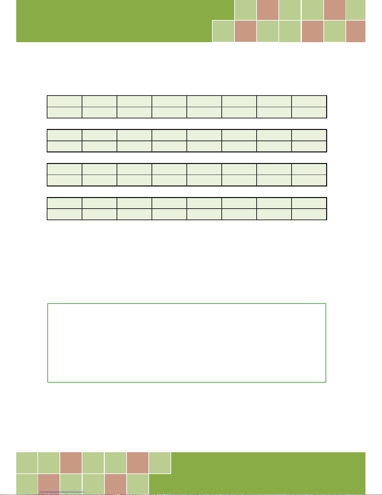
6.3.7 I/O Selection Control Register
(Write): wBase+0xcc
Bit 7 Bit 6 Bit 5 Bit 4 Bit 3 Bit 2 Bit 1 Bit 0
0 0 0 0 0 Port2 Port1 Port0
(Write): wBase+0xdc
Bit 7 Bit 6 Bit 5 Bit 4 Bit 3 Bit 2 Bit 1 Bit 0
0 0 0 0 0 Port5 Port4 Port3
(Write): wBase+0xec
Bit 7 Bit 6 Bit 5 Bit 4 Bit 3 Bit 2 Bit 1 Bit 0
0 0 0 0 0 Port8 Port7 Port6
(Write): wBase+0xfc
Bit 7 Bit 6 Bit 5 Bit 4 Bit 3 Bit 2 Bit 1 Bit 0
0 0 0 0 0 Port11 Port10 Port9
These registers provide the function for configuration digital input/output port of the PIO-D96
series Card. Every I/O port can be programmed to be a DI or a DO port. Note that all ports are used
as D/I ports when the PC is first turned on.
port?=1 this port is used as a DO port
port?=0 this port is used as a DI port
For example:
outportb(wBase+0xcc,0x03); /* set port0 ~ port1 as DO ports */
/* set port2 as DI ports */
outportb(wBase+0xdc,0x07); /* set port3 ~ port5 as D/O ports */
outportb(wBase+0xec,0x00); /* set port6 ~ port8 as DI ports */
Page 46
PIO-D96 Series Card
96-channel DIO Board
User Manual, Ve r. 2.3, Jun. 2018, PMH-008-23 Page: 45
6.3.8 Card ID Register
(Read): wBase+0xfc
Bit 7 Bit 6 Bit 5 Bit 4 Bit 3 Bit 2 Bit 1 Bit 0
0 ID3 ID2 ID1 ID0 0 0 0
For example:
wCardID = inportb(wBase+0xfc); /* read Card ID */
Note: The Card ID function is only supported by the PIO-D96U/D96SU and PEX-D96S (Ver. 1.0 or above)
6.3.9 Read/Write 8-bit Data Register
(Read/Write): wBase+0xc0/0xc40xc8/0xd0/0xd4/0xd8
0xe0/0xe4/0xe8/0xf0/0xf4/0xf8
Bit 7 Bit 6 Bit 5 Bit 4 Bit 3 Bit 2 Bit 1 Bit 0
D7 D6 D5 D4 D3 D2 D1 D0
There are 12 8-bit I/O ports in the PIO-D96 series card. Every I/O port can be configured as DI or DO
port. User can send/receive digital data to/from this register for digital input or output. Note that all
ports are used as D/I port when the PC is first turned on.
For example:
outportb(wBase+0xc0,Val); /* write to Port0 */
Val=inportb(wBase+0xc0); /* read from Port0 */
Note: Make sure the I/O port configuration (DI or DO) before read/write the data register, refer to Section 6.3.7
“I/O Selection Control Register” for more details.
Page 47
PIO-D96 Series Card
96-channel DIO Board
User Manual, Ve r. 2.3, Jun. 2018, PMH-008-23 Page: 46
BCB4 for Borland C
++
Builder 4
PIODIO.H Header files
PIODIO.LIB Linkage library for BCB only
Delphi4 for Delphi 4
PIODIO.PAS Declaration files
VC6 for Visual C
++
6
PIODIO.H Header files
PIODIO.LIB Linkage library for VC only
VB6 for Visual Basic 6
PIODIO.BAS Declaration files
VB.NET2005 for VB.NET2005
PIODIO.vb Visual Basic Source files
CSharp2005 for C#.NET2005
PIODIO.cs Visual C# Source files
7. Demo Programs
7.1 Demo Program for Windows
All demo programs will not work properly if the DLL driver has not been installed correctly. During
the DLL driver installation process , the install-shields will register the correct kernel driver to the
operation system and copy the DLL driver and demo programs to the correct position based on the
driver software package you have selected (Win 98/Me/NT/2K and 32-/64-bit win
XP/2003/2008/7/8/10). Once driver installation is complete, the related demo programs and
development library and declaration header files for different development environments will be
presented as follows.
Demo Program for PIO-DIO Series Class ic D riv er
The demo program is contained in:
CD:\NAPDOS\PCI\PIO-DIO\DLL_OCX\Demo\
http://ftp.icpdas.com/pub/cd/iocard/pci/napdos/pci/pio-dio/dll_ocx/demo/
For detailed information about the DLL function of the PIO-D96 series, refer to PIO-DIO DLL
Software Manual (CD:\NAPDOS\PCI\PIO-DIO\Manual\)
Page 48
PIO-D96 Series Card
96-channel DIO Board
User Manual, Ve r. 2.3, Jun. 2018, PMH-008-23 Page: 47
BCB6 for Borland C
++
Builder 6
UniDAQ.H Header files
UniDAQ.LIB Linkage library for BCB only
Delphi6 for Delphi 6
UniDAQ.PAS Declaration files
CSharp2005 for C#.NET2005
UniDAQ.cs Visual C# Source files
VB.NET2005 for VB.NET2005
UniDAQ.vb Visual Basic Source files
VC6 for Visual C
++
6
UniDAQ.H Header files
UniDAQ.LIB Linkage library for VC only
VB6 for Visual Basic 6
UniDAQ.BAS Declaration files
VC.NET2005 for VC.NET2005 (32-bit)
UniDAQ.H Header files
UniDAQ.LIB Linkage library for VC only
VC.NET2005 for VC.NET2005 (64-bit)
UniDAQ.H Header files
UniDAQ.LIB Linkage library for VC only
Demo Program for UniDAQ SDK Driver
The demo program is contained in:
CD:\NAPDOS\PCI\UniDAQ\DLL\Demo\
http://ftp.icpdas.com/pub/cd/iocard/pci/napdos/pci/unidaq/dll/demo/
For detailed information about the DLL function and demo program of the UniDAQ, refer to
UniDAQ DLL Software Manual (CD:\NAPDOS\PCI\UniDAQ\Manual\)
Page 49
PIO-D96 Series Card
96-channel DIO Board
User Manual, Ve r. 2.3, Jun. 2018, PMH-008-23 Page: 48
\TC\*.* for Turbo C 2.xx or above
\MSC\*.* for MSC 5.xx or above
\BC\*.* for BC 3.xx or above
\TC\LIB\*.* for TC Library
\TC\DEMO\*.* for TC demo program
\TC\DIAG\*.* for TC diagnostic program
\TC\LIB\PIO.H TC Declaration File
\TC\LIB\TCPIO_L.LIB TC Large Model Library File
\TC\LIB\TCPIO_H.LIB TC Huge Model Library File
\MSC\LIB\PIO.H MSC Declaration File
\MSC\LIB\MSCPIO_L.LIB MSC Large Model Library File
\MSC\LIB\MSCPIO_H.LIB MSC Huge Model Library File
\BC\LIB\PIO.H BC Declaration File
\BC\LIB\BCPIO_L.LIB BC Large Model Library File
\BC\LIB\BCPIO_H.LIB BC Huge Model Library File
7.2 Demo Program for DOS
The demo program is contained in:
CD:\NAPDOS\PCI\PIO-DIO\DOS\d96\
http://ftp.icpdas.com/pub/cd/iocard/pci/napdos/pci/pio-dio/dos/d96/
For detailed information about the DLL function of the DOS, please refer to PIO-DIO DL L
Software Manual (CD:\NAPDOS\PCI\PIO-DIO\Manual\)
Page 50
PIO-D96 Series Card
96-channel DIO Board
User Manual, Ve r. 2.3, Jun. 2018, PMH-008-23 Page: 49
Appendix: Daughter Board
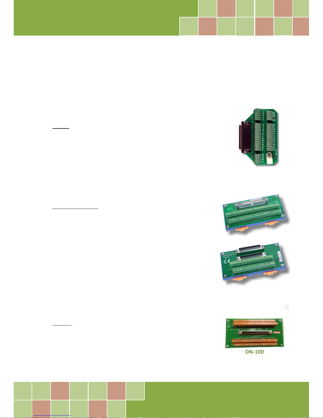
A1. DB-37, DN-37, DN-50 and DN-100
DB-37: The DB-37 is a general purpose daughter board for D-sub 37 pins. It
is designed for easy wire connection via pin-to-pin. Use a 37-pin cable (e.g.
CA-3710, etc.) to connect DB-37 to CON1 of the PIO-D96/D96U.
DN-37 and DN-50: The DN-37 is a general purpose daughter board
for DB-37 pins with DIN-Rail Mountings. The DN-50 is designed for
50-pin flat-cable headers win DIN-Rail mountings. They are also
designed for easy wire connection via pin-to-pin.
Use a 37-pin cable (e.g. CA-3710, etc.) to connect to CON1 of the
PIO-D96/D96U by DN-37, and then use a 50-pin cable (e.g. CA-5002,
etc.) to connect to CN2/CN2/CN3 by DN-50.
DN-100: The DN-100 is a general purpose daughter board for SCSI II
100 pins. It is designed for easy wire connection via pin-to-pin. Use
a 100-pin SCSI II cable (e.g. CA-SCSI100-15 ,etc.) to connect DN-100
to CON1 of the PIO-D96SU/PEX-D96S.
DN-37
DN-50
DB-37
DN-100
Page 51
PIO-D96 Series Card
96-channel DIO Board
User Manual, Ve r. 2.3, Jun. 2018, PMH-008-23 Page: 50
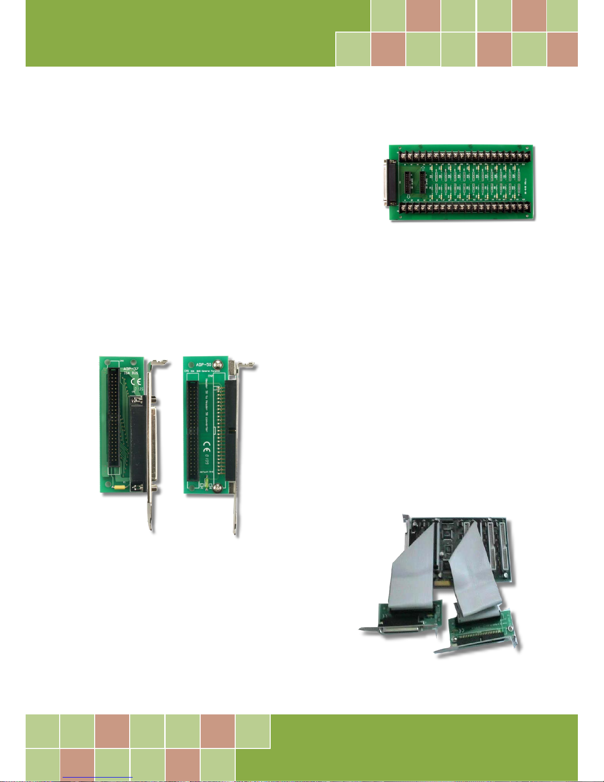
A2. DB-8125
The DB-8125 is a general purpose screw terminal board. It is
designed for easy wire connection. The DB-8125 consists of one
DB-37 and two 20-pin flat-cable headers. Use a 37-pin cable (e.g.
CA-3710, etc.) to connect DB-8125 to CON1 of the PIO-D96(U).
A3. ADP-37/PCI and ADP-50/PCI
The ADP-37/PCI and ADP-50/PCI are extender for the
50-pin header. The one side of the ADP-37/PCI or the
ADP-50/PCI can be connected to a 50-pin header. Note:
that ADP-37/PCI is 50-pin header to DB-37 extender and
ADP-50/PCI is 50-pin header to 50-pin header extender.
The other side can be mounted onto the PC chassis as is
depicted by the following:
DB-8125
ADP-37/PCI
ADP-50/PCI
Page 52
PIO-D96 Series Card
96-channel DIO Board
User Manual, Ve r. 2.3, Jun. 2018, PMH-008-23 Page: 51
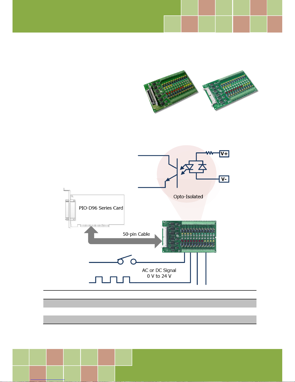
A4. DB-24P and DB-24PD Isolated Input Board
The DB-24P is a 24-channel isolated digital
input daughter board. The optically isolated
inputs of the DB-24P consist of a bi-directional
optocoupler with a resistor for current sensing.
You can use the DB-24P to sense DC signals
from TTL levels up to 24 V or use the DB-24P
to sense a wide range of AC signals. You can also use this board to isolate the computer from large
common-mode voltage, ground loops and transient voltage spikes that often occur in industrial
environments, as illustrated below. Table A4-1 is the comparison of DB-24P and DB-24PD.
Table A4-1:
DB-24P
DB-24PD
50-pin Flat-Cable Header
Yes Yes
D-sub 37-pin Header
No
Yes
Other Specifications
Same
DB-24PD
DB-24P
PIO-D96 Series Card
Page 53
PIO-D96 Series Card
96-channel DIO Board
User Manual, Ve r. 2.3, Jun. 2018, PMH-008-23 Page: 52
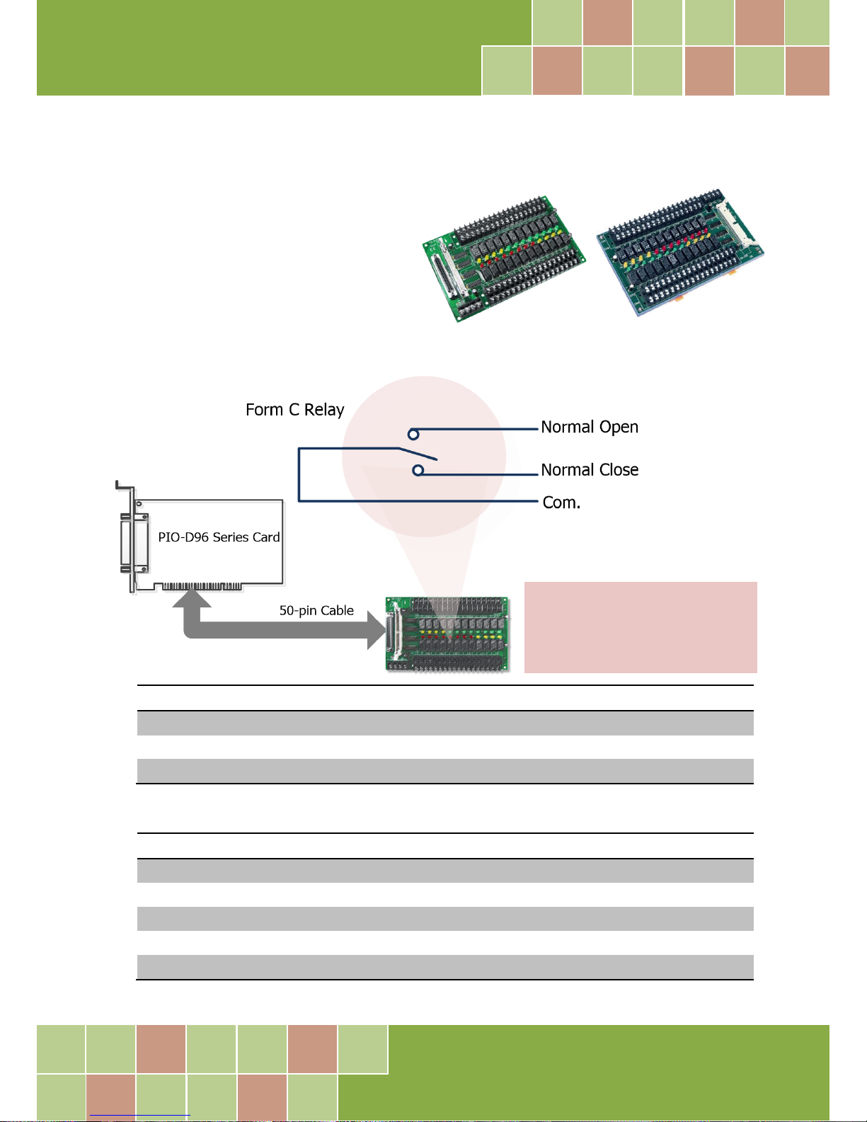
A5. DB-24R and DB-24RD Relay Board
The DB-24R, 24-channel relay output board,
consists of 24 form-C relays for efficiently
controlling the switch with the use of an
appropriately loaded program. The relays are
energized by applying a 12 V/24 V voltage
signal to the appropriate relay channel on the
50-pin flat-cable connector. There are 24 enunciator LEDs for each relay channel and the LED light
will go on when their associated relay has been activated. The control scheme is illustrated below.
Table A5-1:
DB-24R
DB24RD
50-pin Flat-Cable Header
Yes Yes
D-sub 37-pin Header
No
Yes
Other Specifications
Same
Table A5-2:
DB-24R, DB-24RD
24 * Relay (120 V, 0.5 A)
DB-24PR, DB-24PRD
24 * Power Relay (250 V, 5 A)
DB-24POR
24 * PhotoMOS Relay (350 V, 0.1 A)
DB-24SSR
24 * SSR (250 VAC, 4 A)
DB-24C
24 * Open Collector (30 V, 100 mA)
DB-16P8R
16 * Relay (120 V, 0.5 A) + 8 * Isolated Input
DB-24R DB-24RD
Note:
Channel: 24 Form C Relay
Relay: Switching up to 0.5 A at 110 V
AC
or 1 A at 24 V
DC
Page 54
PIO-D96 Series Card
96-channel DIO Board
User Manual, Ve r. 2.3, Jun. 2018, PMH-008-23 Page: 53
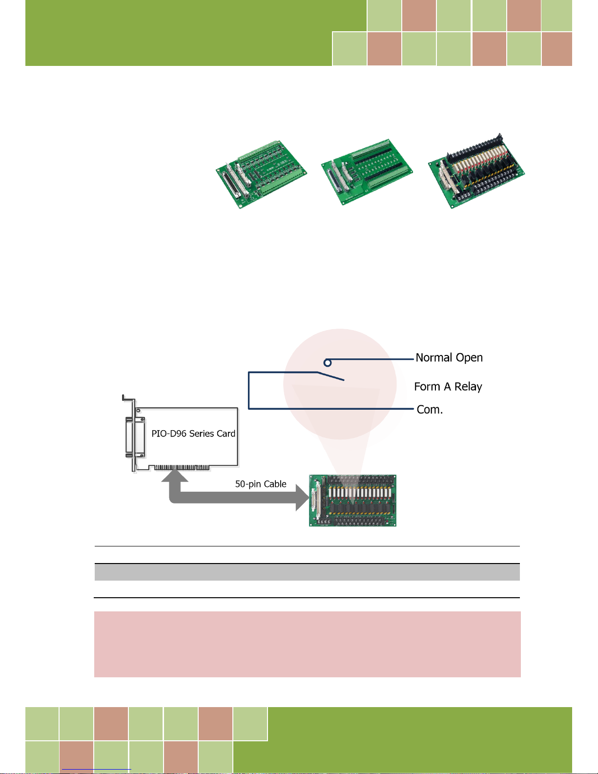
A6. DB-24PR, DB-24POR and DB-24C
The DB-24PR, 24-channel
power relay output board,
consists of 8 Form-C and 16
form-A electromechanical
relays for efficiently
controlling the switch with the use of an appropriately loaded program. The contact of each relay
can allow 5 A current load at 250 VAC/30 VDC. The relay is energized by applying a 5 voltage signal to
the associate relay channel on the 20-pin flat-cable connector (just used 16 relays) or 50-pin
flat-cable connector (OPTO-22 compatible, for DIO-24 series). 24 enunciator LEDs for indicating the
status of for each relay and the corresponding LED light will go on when their associated relay has
been activated. To avoid overloading your PC’s power supply, this board needs a +12 VDC or +24V
DC
external power supply, as illustrated below.
Table A6-1:
DB-24PR
24 * Power Relay, 5A/250 V
DB-24POR
24 * PhotoMOS Relay, 0.1 A/350 VAC
DB-24C
24 * Open Collector, 100 mA per channel, 30 V max.
DB-24PR
DB-24POR
DB-24C
Notes:
1. 50-Pin connector (OPTO-22 compatible) for DIO-24/48/144, PIO-D144/D96/D56/D48/D24/D168.
2. 20-Pin connector for 16 channel digital output (A-82X, A-62X, DIO-64, ISO-DA16/DA8).
3. Channel: 16 Form A Relay, 8 Form C Relay.
4. Relay: switching up to 5 A at 110 VAC/5 A at 30 VDC.
Page 55
PIO-D96 Series Card
96-channel DIO Board
User Manual, Ve r. 2.3, Jun. 2018, PMH-008-23 Page: 54
A7. Daughter Boards Comparison Table
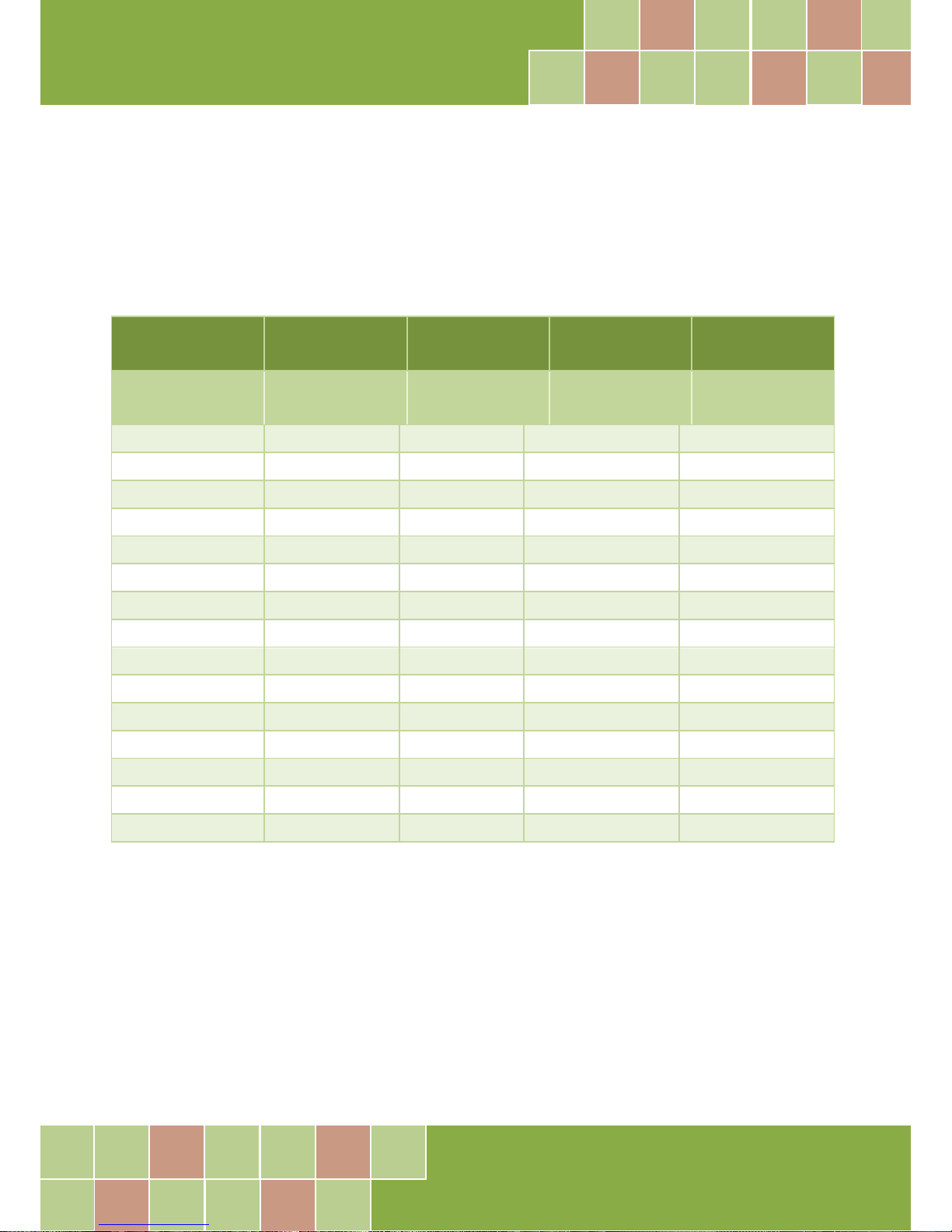
Table A7-1 is the comparison table for the daughter application of PIO/PISO series cards.
Table A7-1:
I/O Card -
PIO-D96
PIO-D96U
PIO-D96
PIO-D96U
PIO-D96SU
PEX-D96S
Cable/
Daughter Boards
20-Pin
Flat-Cable
50-Pin
Flat-Cable
37-Pin
D-sub
100-Pin
SCSI II
DB-37 NO NO Yes NO
DN-37 NO NO Yes NO
ADP-37/PCI NO Yes Yes NO
ADP-50/PCI NO Yes NO NO
DB-24P NO Yes NO NO
DB-24PD NO Yes Yes NO
DB-16P8R NO Yes Yes NO
DB-24R NO Yes NO NO
DB-24RD NO Yes Yes NO
DB-24C Yes Yes Yes NO
DB-24PR Yes Yes NO NO
DB-24PRD NO Yes Yes NO
DB-24POR Yes Yes Yes NO
DB-24SSR NO Yes Yes NO
DN-100 NO NO NO Yes
 Loading...