

Page 1
For PETL-7060
English/ November 2010/ Version 1.1
What’s in the shipping package?
The package includes the following items:
PETL-7060
Software CD
Quick Start Guide
(
This Document)
Preparations for devices
1. Power Supply:+12 ~ +48 VDC
2. Ethernet Hub or PoE Ethernet Switch.
3. Make sure your PC has workable network settings.
4. Disable or well configure your Windows firewall and Anti-Virus
firewall first, else the “Search Servers” on page 5 may not
work. (Please contact with your system Administrator)
PETL-7060 Quick Start Guide
Page 2
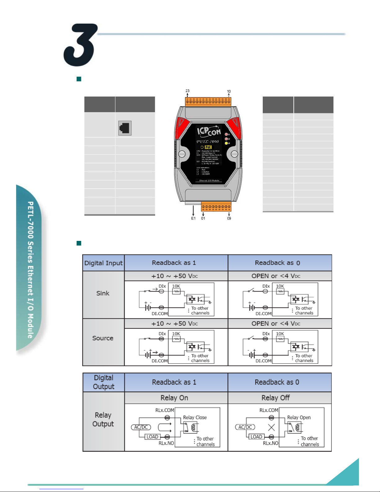
Pin Assignments and Wiring Note
Pin Assignments
Terminal
No.
Pin
Assignment
23 RL5 COM
22 RL5 NO
21 RL4 COM
20 RL4 NO
19 RL3 COM
18 RL3 NO
17 RL2 COM
16 RL2 NO
15 RL1 COM
14 RL1 NO
13 RL0 COM
12 RL0 NO
11 N/A
10 N/A
Terminal
No.
Pin
Assignment
E1
RJ-45
01 DI5
02 DI4
03 DI3
04 DI2
05 DI1
06 DI0
07 DI.COM
08 (R)+Vs
09 (B)GND
Digital Input/Output Wiring
PETL-7060 Quick Start Guide
Page 3
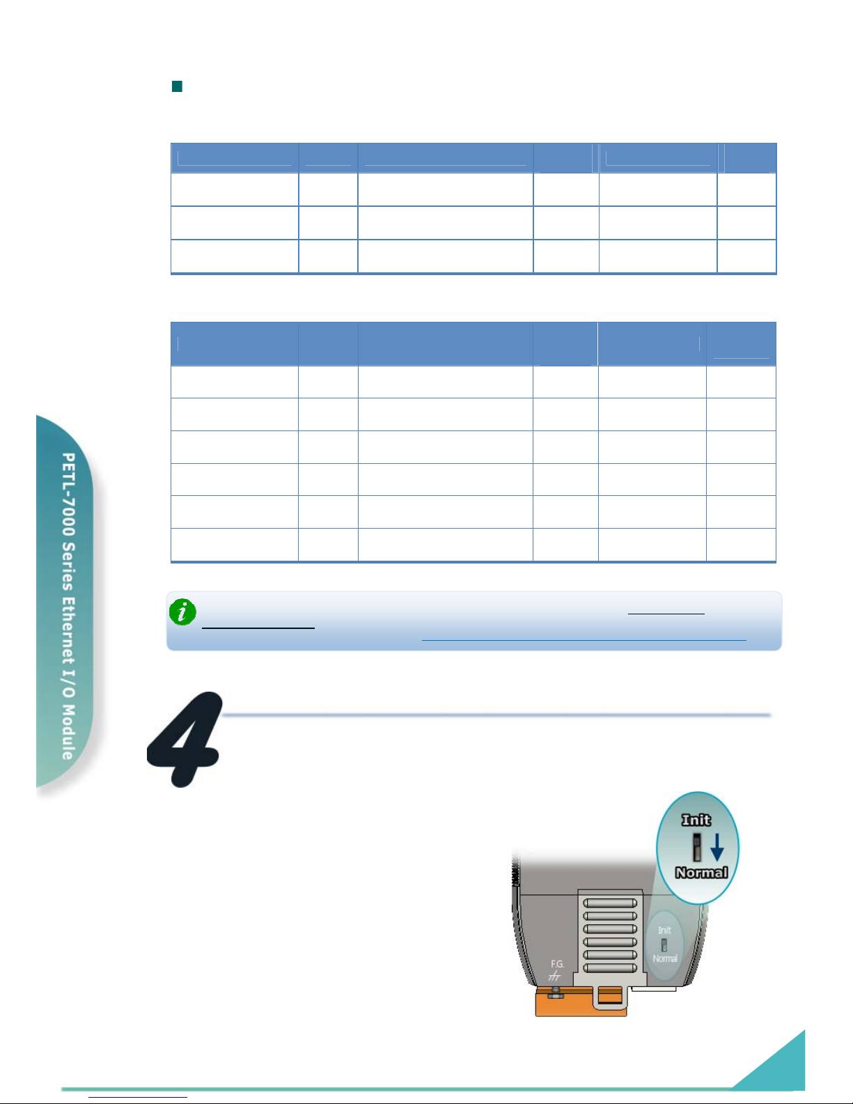
DI/DO Modbus Address
(1xxxx) DI address:
Begin address Points Description
Bits per
Point
Range
Access
Type
0
(0x0)
1~6 Digital Input 1
0:Off
1:On
R
32
(0x20)
1~6
Digital latched status
(high)
1
0:no
1:latched
R
64
(0x40)
1~6
Digital latched status
(low)
1
0:no
1:latched
R
(0xxxx) DO address:
Begin address Points Description
Bits
per
Point
Range
Access
Type
0
(0x0)
1~6 Digital Output 1
0: Off
1:On
R/W
32
(0x20)
1
Clear all DI latched
status (high)
1 1: Clear W
33
(0x21)
1
Clear all DI latched
status (low)
1 1: Clear W
.
.
.
.
.
.
.
.
.
.
.
.
235
(0xEB)
1~6 Power-on value for DO 1
0=Off
1=On
R/W/F
267
(0x10B)
1~6 safe value for DO 1
0=Off
1=On
R/W/F
For detail “DI/DO Modbus Address” information, please refer to section 5.3 Modbus
Register Address
of user’s manual. CD:\NAPDOS\PETL7000\Document\
Connecting the Power and Host PC
ftp://ftp.icpdas.com/pub/cd/6000cd/napdos/petl7000/document/
1. Check Init/Normal switch is
on Normal position.
PETL-7060 Quick Start Guide
Page 4
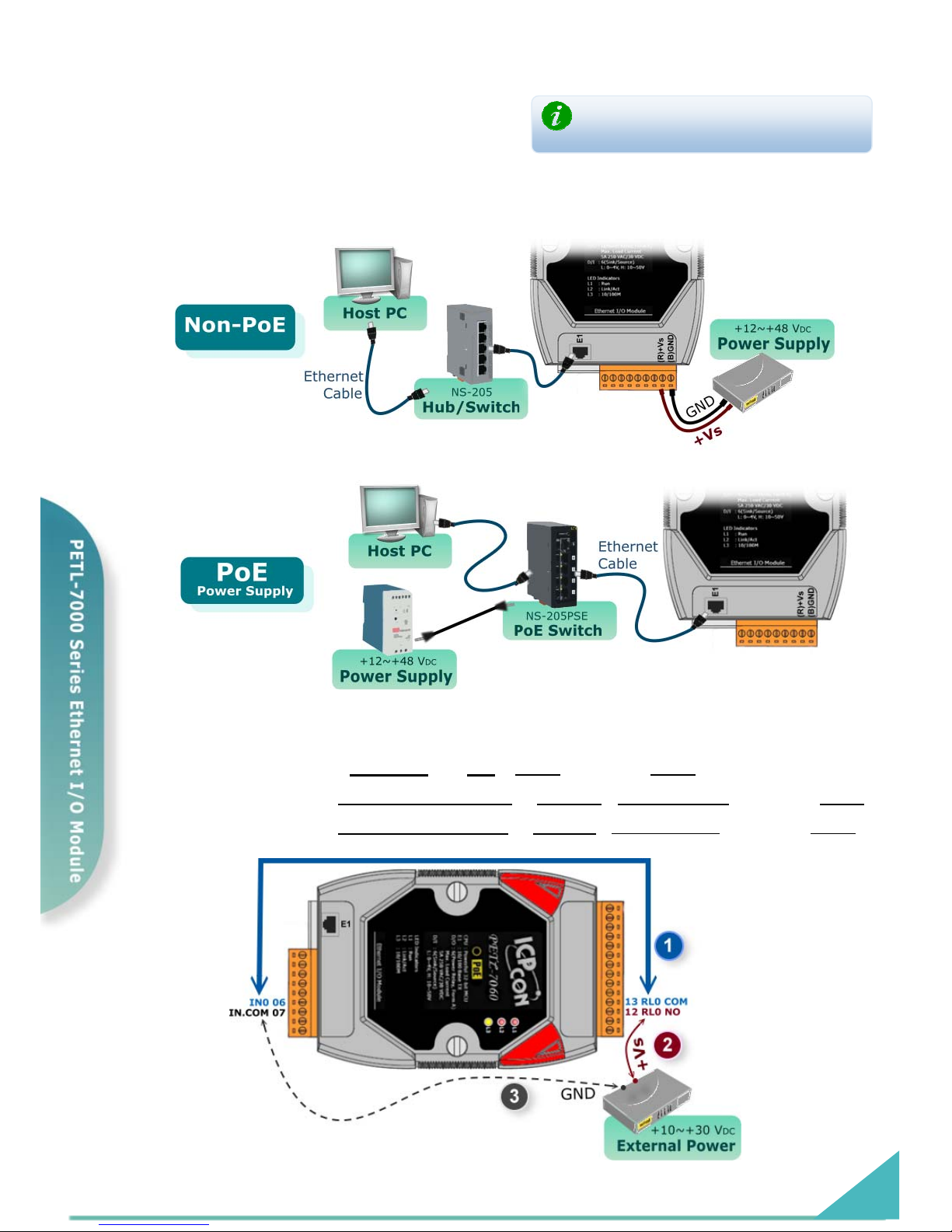
2. Connect both the PETL-7060 and PC to the same sub network
or the same Ethernet Switch.
The function of the Ethernet LED on PETL-
7000 RJ-45 is reserved (Function: N/A).
3. Apply power to the PETL-7060. The valid power voltage range
is from +12 to +48 V
DC.
4. Wire the DI and DO for self test. The wiring as follows:
1. Connect the RL0 COM and IN0. ( Pin13 connect to Pin06)
2. Supply the External Power +10V
to RL0 NO. (External +10V connect to Pin12 )
3. Supply the External Power GND
to IN.COM. (External GND connect to Pin07)
PETL-7060 Quick Start Guide
Page 5
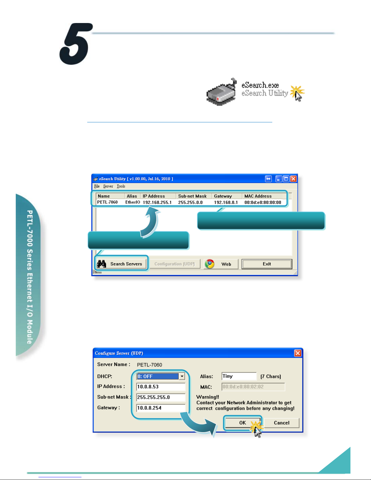
Configuring Ethernet Settings
1. Run the eSearch Utility.
The eSearch Utility is located at:
CD:\Napdos\Software\eSearch\
ftp://ftp.icpdas.com/pub/cd/6000cd/napdos/software/eSearch/
2. Click “Search Servers” button to search your PETL-7060.
3. Double-Click your PETL-7060 to configure the settings.
4. Contact your Network Administrator to get correct network
configuration. Modify the network settings and then click “OK”
button. The PETL-7060 will restart it-self immediately.
1. Click “Search Servers
”
2. Double-Click your PETL-7000
PETL-7060 Quick Start Guide
Page 6
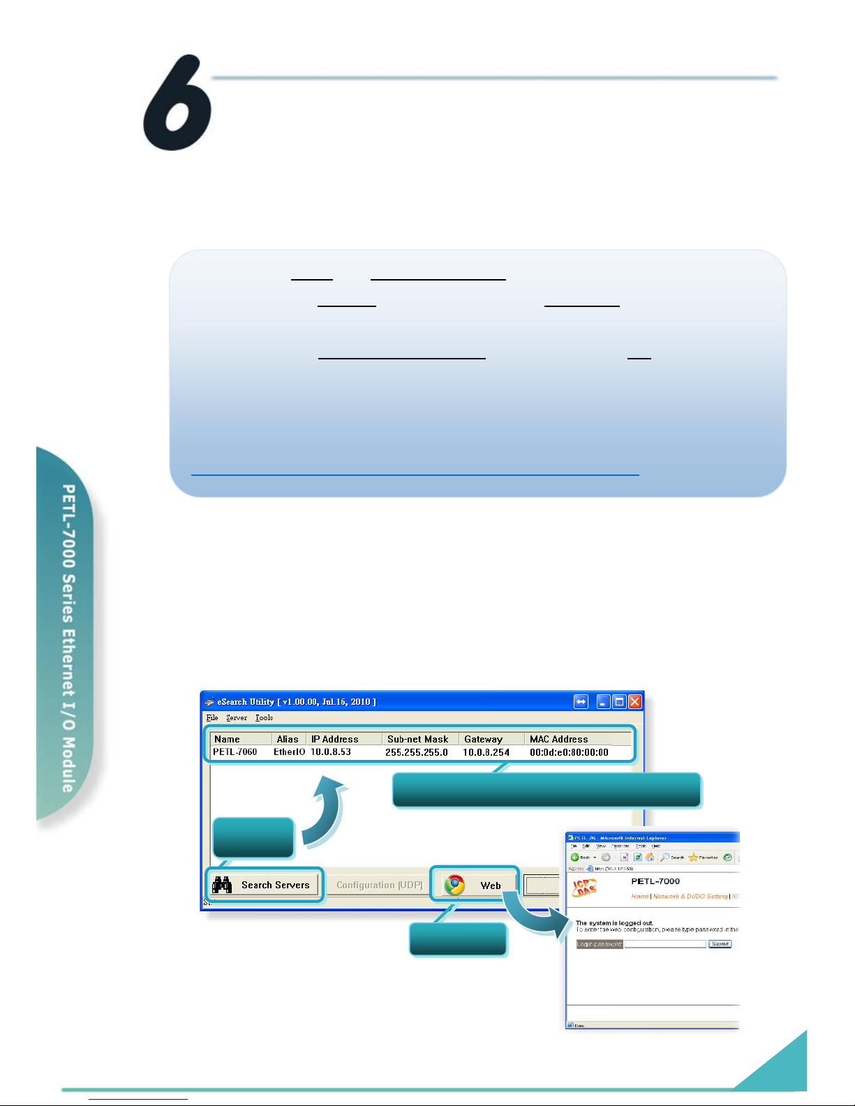
Testing your PETL-7000
Notes: In order to avoid accessing error in “IE” browser, please
disable your IE cache as following:
Notes: In order to avoid accessing error in “IE” browser, please
disable your IE cache as following:
Step 1: Click “ToolsStep 1: Click “Tools” >> “Internet Options...” in the menu items.
Step 2: Click the “General” tab and then click the “Settings...” button in Temporary
Internet files frame.
Step 3: Click the “Every visit to the page
” and then click the “OK” button in
Settings box and Internet Options box.
For more detail, please refer to the user manual (Page 77)
C:\ Napdos\PETL7000\Document\
http://ftp.icpdas.com/pub/cd/6000cd/napdos/petl7000/document/
1. Wait 2 seconds and then click the “Search Servers” button
again to ensure the PETL-7060 is working well with new
configuration.
2. Click the “Web” button to link the PETL-7060 web server.
1. Clickyour PETL-7000 on the list
Click
2. Click
PETL-7060 Quick Start Guide
Page 7
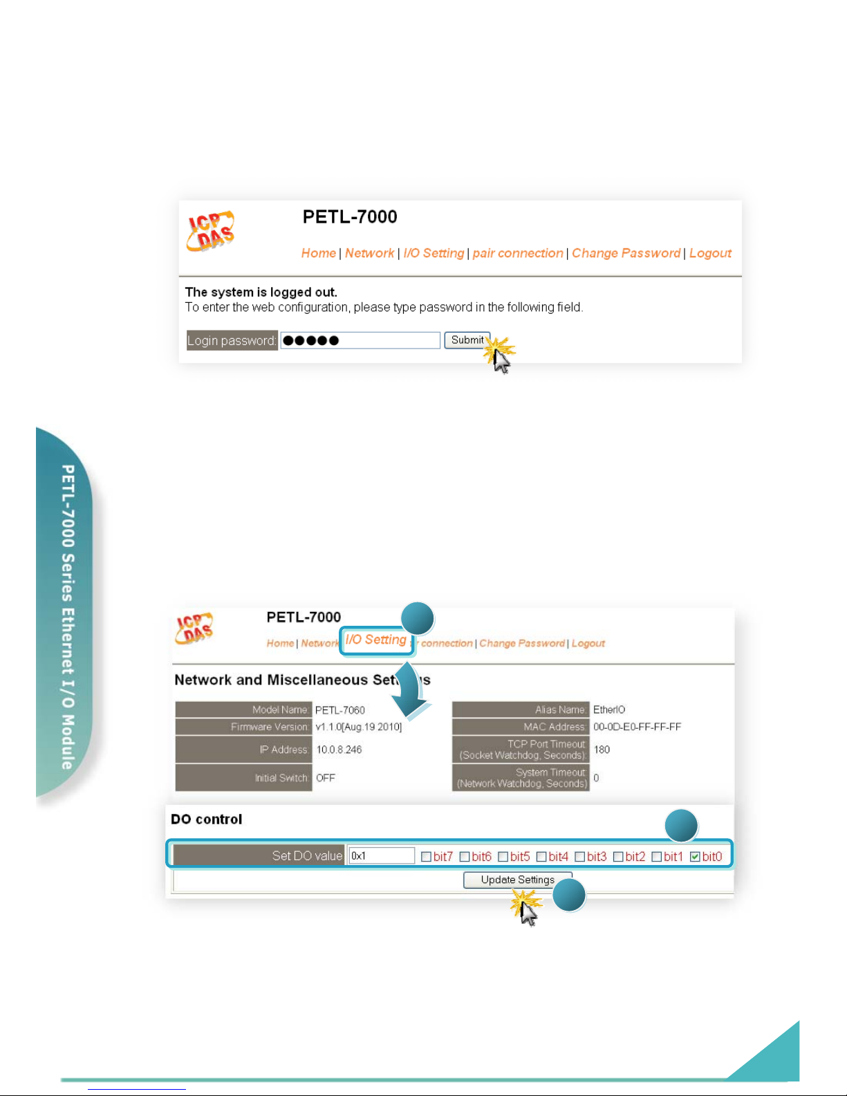
3. Enter the password and click the “Submit” button to enter
the configuration web page. (The factory default password:
Admin)
4. Control the I/O for simple test.
In the I/O Setting page, check the “bit0” checkbox for setting ON to DO0 and
click “Update Settings” button.
PETL-7060 Quick Start Guide
Page 8
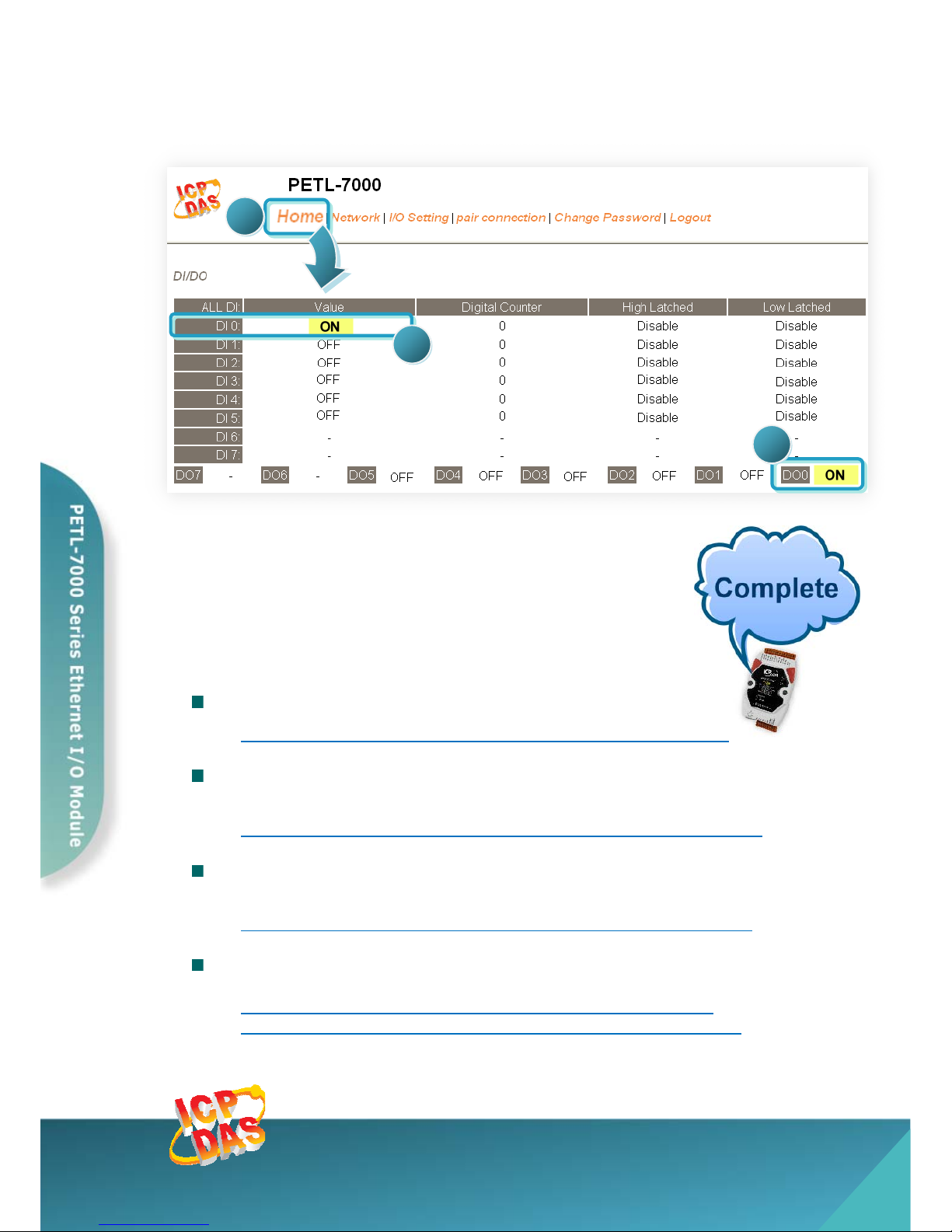
In the Home page, check that the DO0 and DI0 status should show current status
are “ON”.
Related Information
PETL-7060 Series Product Page:
http://www.icpdas.com/products/Industrial/petl7k/petl-7060.htm
PETL-7000 Series Documentations:
CD:\Napdos\PETL7000\document\
http://ftp.icpdas.com.tw/pub/cd/6000cd/napdos/ptel7000/document/
PETL-7000 Series Firmware:
CD:\ Napdos\PETL7000\firmware\
http://ftp.icpdas.com.tw/pub/cd/6000cd/napdos/petl7000/firmware/
NS-205, NS-205PES Product Page (optional):
http://www.icpdas.com/products/Switch/industrial/ns-205.htm
http://www.icpdas.com/products/Switch/industrial/ns-205pse.htm
ICP DAS Web Site: http://www.icpdas.com
Contact Us (E-Mail): [email protected] , [email protected]
Copyright @ 2010 by ICP DAS Co., Ltd. All Rights Reserved.
 Loading...