

Page 1
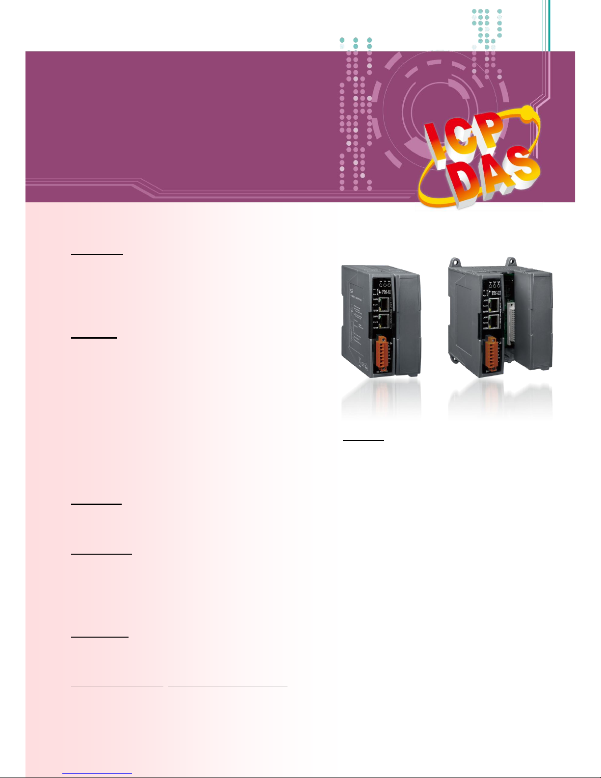
PDS-8x1 Series
User Manual Ver. 1.1.2
Programmable Device Server with I/O Expansion Slot(s)
WARRANTY
All products manufactured by ICP DAS are warranted
against defective materials for a period of one year
from the date of delivery to the original purchaser.
WARNING
ICP DAS assumes no liability for damages consequent
to the use of this product. ICP DAS reserves the right
to change this manual at any time without notice. The
information furnished by ICP DAS is believed to be
accurate and reliable. However, no responsibility is
assumed by ICP DAS for its use, nor for any
infringements of patents or other rights of third
parties resulting from its use.
COPYRIGHT
Copyright © 2014 by ICP DAS. All rights are reserved.
TRADEMARKS
Names are used for identification purposes only and
may be registered trademarks of their respective
companies.
CONTACT US
If you have any questions, please feel free to contact
us via email at:
SUPPORT
This manual relates to the following modules:
PDS-811 and PDS-821
Page 2

Programmable Device Server with I/O Expansion Slot(s)
PDS-8x1 Series User Manual, Version 1.1.2, Apr. 2015 - 2 -
TABLE OF CONTENTS
PACKING LIST ................................................................................................................................................................ 5
MORE INFORMATION ................................................................................................................................................... 5
1. INTRODUCTION ................................................................................................................................................... 6
1.1 SELECTION GUIDE ................................................................................................................................................... 7
1.2 ETHERNET SOLUTIONS ............................................................................................................................................. 8
1.3 VXCOMM TECHNOLOGY .......................................................................................................................................... 9
1.4 WEB SERVER TECHNOLOGY .................................................................................................................................... 11
2. HARDWARE INFORMATION ............................................................................................................................... 12
2.1 SPECIFICATIONS .................................................................................................................................................... 12
2.2 FEATURES ........................................................................................................................................................... 13
2.3 APPLICATIONS ...................................................................................................................................................... 13
2.4 APPEARANCE ....................................................................................................................................................... 14
2.5 DIMENSIONS ........................................................................................................................................................ 16
2.6 PIN ASSIGNMENTS ................................................................................................................................................ 18
2.6.1 PDS-811 and PDS-821 ....................................................................................................................................... 18
2.6.2 I-8112iW ............................................................................................................................................................ 19
2.6.3 I-8114W ............................................................................................................................................................. 20
2.6.4 I-8114iW ............................................................................................................................................................ 21
2.6.5 I-8142iW ............................................................................................................................................................ 22
2.6.6 I-8144iW ............................................................................................................................................................ 23
2.7 WIRING NOTES FOR RS-232/485/422 INTERFACES .................................................................................................. 24
2.7.1 RS-232 Wiring ................................................................................................................................................... 24
2.7.2 RS-422 Wiring ................................................................................................................................................... 25
2.7.3 RS-485 Wiring ................................................................................................................................................... 25
3. SETTING UP THE PDS-8X1 CONTROLLER............................................................................................................. 27
4. WEB CONFIGURATION ....................................................................................................................................... 36
4.1 LOGGING IN TO THE PDS-8X1 WEB SERVER .............................................................................................................. 36
4.2 NETWORK SETTING ............................................................................................................................................... 38
4.2.1 IP Filter Setting .................................................................................................................................................. 42
4.3 COM PORT SETTINGS ........................................................................................................................................... 45
4.3.1 Operation Mode: M0, M1 and M2 .................................................................................................................... 49
Page 3

Programmable Device Server with I/O Expansion Slot(s)
PDS-8x1 Series User Manual, Version 1.1.2, Apr. 2015 - 3 -
4.3.2 Set Remote VCOM3 Connection ........................................................................................................................ 51
4.4 MISC. SETTINGS ................................................................................................................................................... 53
4.4.1 Disable the “Web Read Only” Function ............................................................................................................. 54
4.4.2 Change Password .............................................................................................................................................. 56
4.4.3 Restore to Factory Default Settings .................................................................................................................. 57
5. TYPICAL APPLICATIONS ..................................................................................................................................... 59
5.1 VIRTUAL COM APPLICATION .................................................................................................................................. 59
5.2 ETHERNET I/O APPLICATIONS ................................................................................................................................. 60
5.3 PAIR-CONNECTION APPLICATIONS ............................................................................................................................ 62
6. CONSOLE/TELNET COMMANDS LIST .................................................................................................................. 71
6.1 OPERATION FLOWCHART........................................................................................................................................ 71
6.2 COMPARISON SHEET (INIT, RUN AND CONSOLE MODES) .............................................................................................. 72
6.3 COMMAND LIST ................................................................................................................................................... 73
6.3.1 IPFILTER ............................................................................................................................................................. 74
6.3.2 IPCONF .............................................................................................................................................................. 76
6.3.3 SOCKET .............................................................................................................................................................. 77
6.3.4 COM .................................................................................................................................................................. 78
6.3.5 Broadcast .......................................................................................................................................................... 79
6.3.6 SystemTimeout .................................................................................................................................................. 80
6.3.7 SocketTimeout ................................................................................................................................................... 81
6.3.8 M ....................................................................................................................................................................... 82
6.3.9 EchoCmdNo ....................................................................................................................................................... 83
6.3.10 EndChar .................................................................................................................................................. 84
6.3.11 IP ............................................................................................................................................................ 85
6.3.12 MASK ...................................................................................................................................................... 85
6.3.13 GATEWAY ............................................................................................................................................... 86
6.3.14 MAC ........................................................................................................................................................ 86
6.3.15 NAME ..................................................................................................................................................... 87
6.3.16 ALIAS ...................................................................................................................................................... 87
6.3.17 DHCP ...................................................................................................................................................... 88
6.3.18 UDP ........................................................................................................................................................ 89
6.3.19 VER ......................................................................................................................................................... 90
6.3.20 SAVE ....................................................................................................................................................... 90
6.3.21 LOAD ...................................................................................................................................................... 91
6.3.22 CONFIG ................................................................................................................................................... 93
6.3.23 RESET ...................................................................................................................................................... 94
6.3.24 QUIT ....................................................................................................................................................... 94
Page 4

Programmable Device Server with I/O Expansion Slot(s)
PDS-8x1 Series User Manual, Version 1.1.2, Apr. 2015 - 4 -
APPENDIX A: LINKING TO A DEVELOPMENT PC .......................................................................................................... 95
APPENDIX B: GLOSSARY ............................................................................................................................................100
1. ARP (ADDRESS RESOLUTION PROTOCOL) ................................................................................................................... 100
2. CLIENTS AND SERVERS ............................................................................................................................................. 100
3. ETHERNET .............................................................................................................................................................. 101
4. FIRMWARE ............................................................................................................................................................ 101
5. GATEWAY .............................................................................................................................................................. 101
6. ICMP (INTERNET CONTROL MESSAGE PROTOCOL) ....................................................................................................... 101
7. INTERNET .............................................................................................................................................................. 101
8. IP (INTERNET PROTOCOL) ADDRESS ........................................................................................................................... 102
9. MAC (MEDIA ACCESS CONTROL) ADDRESS ................................................................................................................ 102
10. PACKET ............................................................................................................................................................ 102
11. PING ................................................................................................................................................................ 102
12. RARP (REVERSE ADDRESS RESOLUTION PROTOCOL) ............................................................................................... 103
13. SOCKET ............................................................................................................................................................ 103
14. SUBNET MASK ................................................................................................................................................... 103
15. TCP (TRANSMISSION CONTROL PROTOCOL) ........................................................................................................... 103
16. TCP/IP ............................................................................................................................................................ 104
17. UDP (USER DATAGRAM PROTOCOL) .................................................................................................................... 104
Page 5
Programmable Device Server with I/O Expansion Slot(s)
PDS-8x1 Series User Manual, Version 1.1.2, Apr. 2015 - 5 -
Packing List
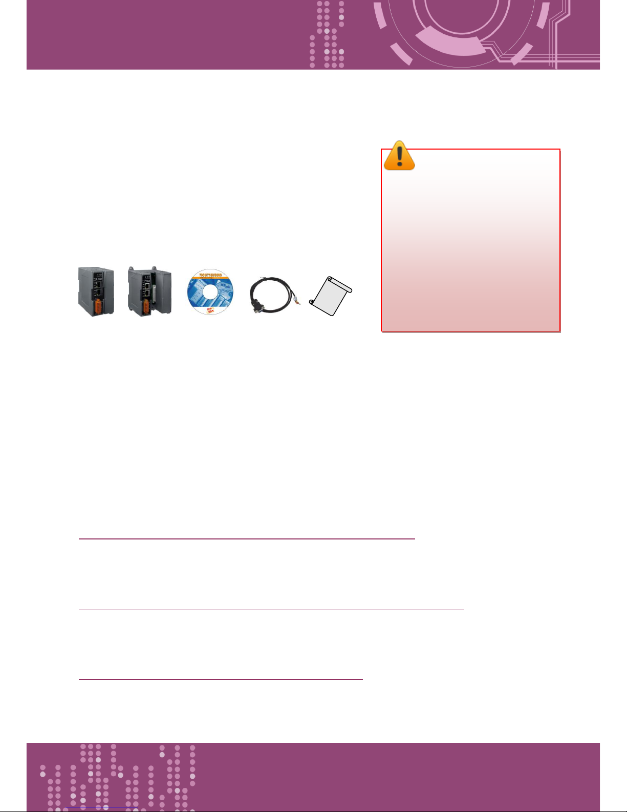
The shipping package includes the following items:
One PDS-811 or PDS-821 series hardware controller
One software utility CD
One download cable (CA-0910)
One printed Quick Start Guide
More Information
Documentation
CD:\NAPDOS\PDS\PDS-8x1\Document
http://ftp.icpdas.com/pub/cd/8000cd/napdos/pds/pds-8x1/document/
Firmware
CD:\NAPDOS\PDS\PDS-8x1\VxComm\Server(PDS)
http://ftp.icpdas.com/pub/cd/8000cd/napdos/pds/pds-8x1/vxcomm/server(pds)/
Software
CD:\NAPDOS\PDS\PDS-8x1
http://ftp.icpdas.com/pub/cd/8000cd/napdos/pds/pds-8x1/
PDS-811 PDS-821 Software CD CA-0910 QuickStart
Note:
If any of these items are missing or
damaged, please contact the local
distributor for more information.
Save the shipping materials and
cartons in case you need to ship
the module in the future.
Page 6
Programmable Device Server with I/O Expansion Slot(s)
PDS-8x1 Series User Manual, Version 1.1.2, Apr. 2015 - 6 -
1. Introduction
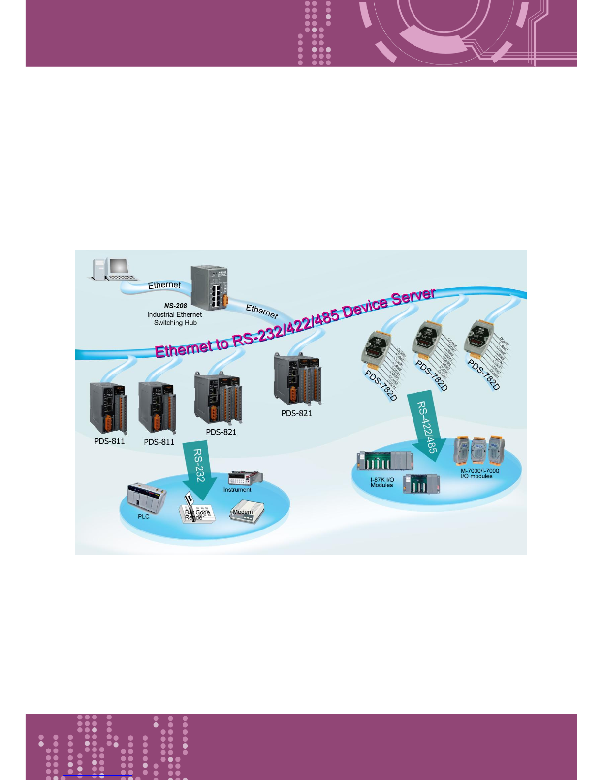
The PDS-811 and PDS-821 programmable device servers (PDS) are compact, modular, intelligent,
rugged, and are designed for networking RS-232 and RS-422/485 serial devices to an Ethernet
network. The PDS-811 has one I/O expansion slot, while PDS-821 has two I/O expansion slots that
can be used to attach various 2- or 4-port serial communication modules. Therefore, a maximum of
4 serial ports can be installed on the PDS-811 or a maximum of 8 serial ports can be installed on the
PDS-821.
Note: There is no serial module built-in to the PDS-811 or PDS-821 by default.
The PDS-811 and PDS-821 controllers are equipped with a 2-port 10/100 Base-TX Ethernet Switch
that can be used to connect two network segments. The Ethernet Switch processes and routes data
on the data-link layer (layer 2) of the OSI model to create a different collision domain per switch
port. Using a switch allows you to attain dedicated bandwidth on point-to-point connections with
every computer, and therefore run in full duplex mode with no collisions. Furthermore, the built-in
2-port Ethernet Switch on the PDS-811/821 enables network wiring to be simplified by cascading
your Ethernet devices.
The PDS-8x1 series contains a built-in operating system, the MiniOS7, which offers a stable and high
performance environment that is similar to DOS. The MiniOS7 can boot up the PDS-8x1 series
within just one second, with the added benefit of no virus problems and a small footprint.
Furthermore, the PDS-8x1 series is designed for low power consumption, maintenance elimination
(no hard disk and no fan), and is constructed from fire retardant materials (UL94-V0 level) with a
robust case.
Page 7

Programmable Device Server with I/O Expansion Slot(s)
PDS-8x1 Series User Manual, Version 1.1.2, Apr. 2015 - 7 -
1.1 Selection Guide
PDS-8x1 Series controllers Selection Guide
Model
PDS-811
PDS-821
Slots
1
2
CPU
80186
(80 MHz)
80186
(80 MHz)
RAM/Flash Disk
512 KB/512 KB
512 KB/512 KB
Ethernet
2-Port Ethernet Switch
2-Port Ethernet Switch
Operating System
MiniOS7
MiniOS7
Console Port
3-wire RS-232
3-wire RS-232
Serial Ports
(Optional) Max.
4
8
Optional Serial Modules Selection Guide
Model
I-8112iW
I-8114W
I-8114iW
I-8142iW
I-8144iW
Interface
9-wire
RS-232
9-wire
RS-232
5-wire
RS-232
4-wire RS-422
2-wire RS-485
4-wire RS-422
2-wire RS-485
Ports 2 4 4 2
4
FIFO
128 Bytes
128 Bytes
128 Bytes
128 Bytes
128 Bytes
Isolation
3000 V
-
3000 V
3000 V
3000 V
Self-tuner - - - Yes
Yes
Connector
DB-9
DB-37
DB-37
Terminal
Block
Terminal
Block
Note:
2-wire RS-485: Data+, Data- with Self-Tuner inside
4-wire RS-422: TxD+, TxD-, RxD+, RxD-
3-wire RS-232: RxD, TxD, GND
5-wire RS-232: RxD, TxD, CTS, RTS, GND
9-wire RS-232: RxD, TxD, CTS, RTS, DSR, DTR, DCD, RI, GND
Page 8
Programmable Device Server with I/O Expansion Slot(s)
PDS-8x1 Series User Manual, Version 1.1.2, Apr. 2015 - 8 -
1.2 Ethernet Solutions
Nowadays, the Ethernet protocol has become the foremost standard for local area networks.
Connectivity via the Internet is now common in many of the latest applications from home
appliances, to vending machines, to testing equipment, to UPS, etc. An Ethernet network can link
office automation and industrial control networks, access remote systems and share data and
information between machines from multiple vendors, and also provides a cost-effective solution
for industrial control networks.
Page 9
Programmable Device Server with I/O Expansion Slot(s)
PDS-8x1 Series User Manual, Version 1.1.2, Apr. 2015 - 9 -
1.3 VxComm Technology
In general, writing a TCP/IP program is more difficult than writing a COM Port program. Another
issue is that perhaps the existing the COM Port communication system was built many years ago
and is now outdated.
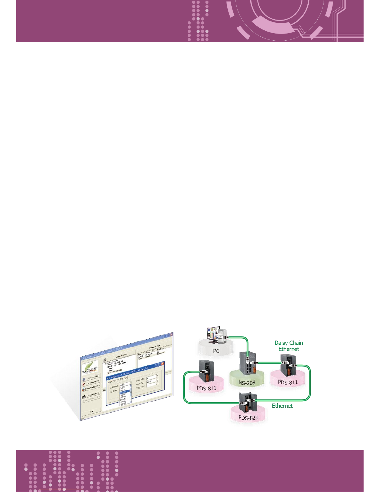
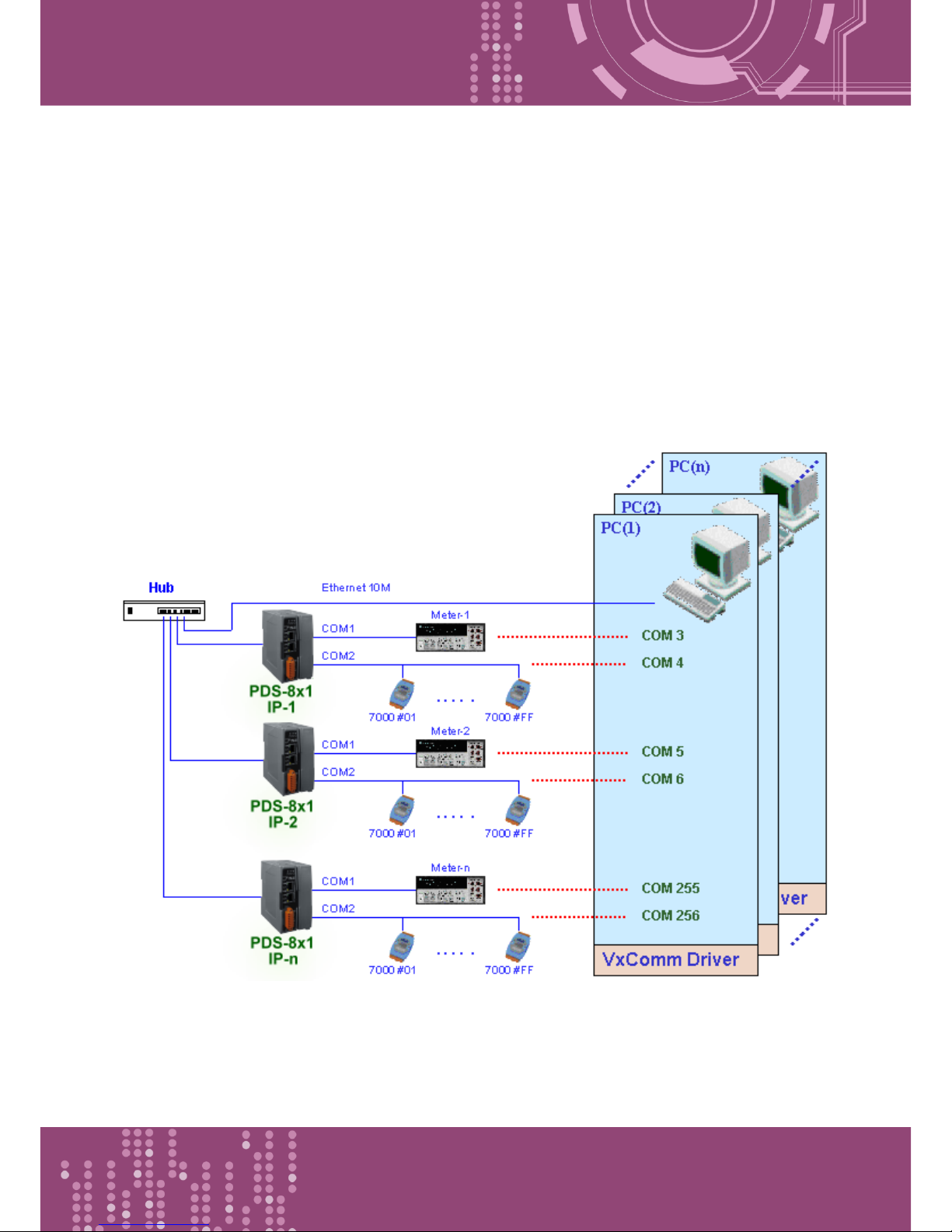
As a result, a new technology, VxComm was developed to virtualize the COM Ports of the PDS-8x1
controller to allow up to 256 COM Ports to be used on a central computer. The VxComm driver
saves time when accessing serial devices through the Ethernet without the need for
reprogramming the COM Port software on the PC.
Page 10
Programmable Device Server with I/O Expansion Slot(s)
PDS-8x1 Series User Manual, Version 1.1.2, Apr. 2015 - 10 -
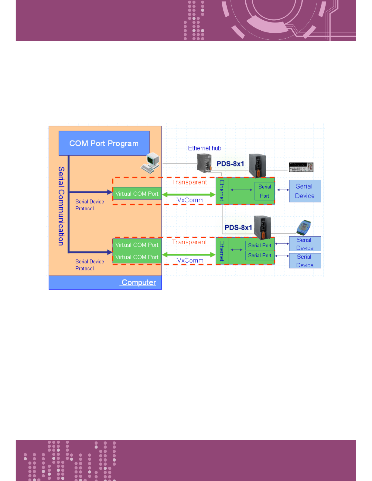
The VxComm driver controls all the details of the Ethernet TCP/IP programming technique,
meaning that, with the assistance of PDS-8x1 controller and VxComm technology, your COM Port
program will be able to access your serial devices through the Ethernet in the same way as through
a COM Port.
Page 11
Programmable Device Server with I/O Expansion Slot(s)
PDS-8x1 Series User Manual, Version 1.1.2, Apr. 2015 - 11 -
1.4 Web Server Technology
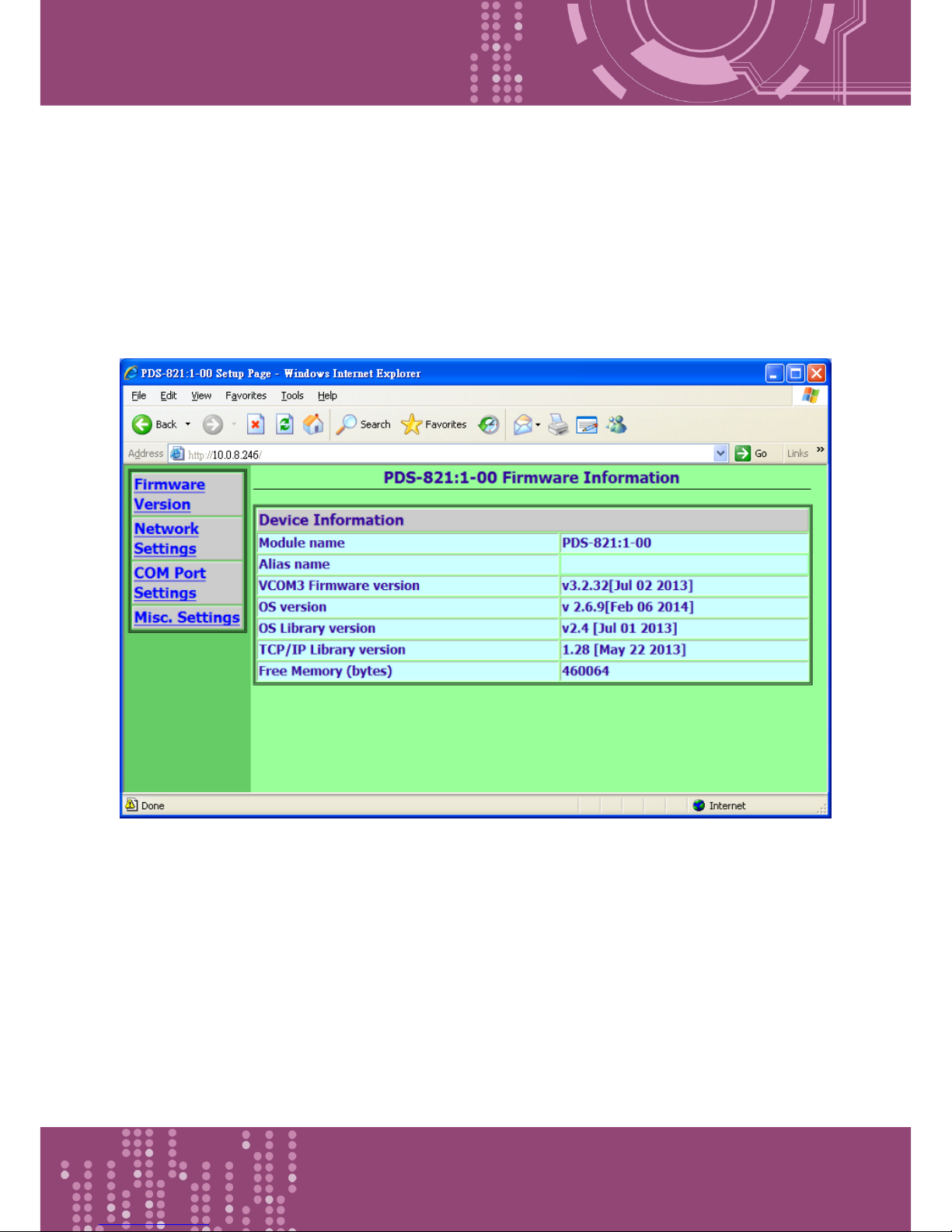
Web server technology enables the PDS-8x1 controller to be configured via a standard web browser
interface, e.g. Google Chrome, Internet Explorer, or Firefox, etc. This means that it is easy to check
the configuration of the PDS-8x1 controller via an Ethernet network without needing to install any
other software tools, thereby reducing the learning curve required for maintaining the device.
Page 12
Programmable Device Server with I/O Expansion Slot(s)
PDS-8x1 Series User Manual, Version 1.1.2, Apr. 2015 - 12 -
2. Hardware Information
This chapter provides a detailed description of the front panel, the hardware specifications, the pin
assignments, the wiring notes and the dimensions for the PDS-8x1 controller.
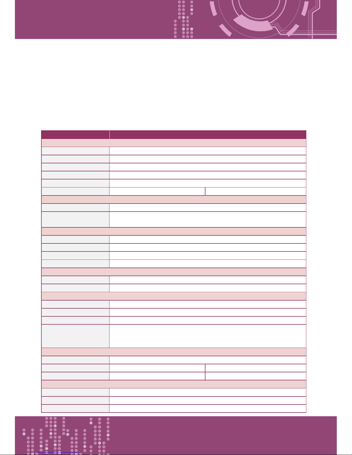
2.1 Specifications
Models
PDS-811
PDS-821
CPU
CPU
80186-80 MHz or compatible
SRAM
512 KB
Flash Memory
512 KB
EEPROM
16 KB
Built-in Watchdog Timer
Yes
I/O Expansion Slots
1 Slot
2 Slots
Communication Interface
COM1 (Console)
RS-232 (TxD, RxD, GND)
Ethernet
2-port 10/100 Base-TX Ethernet Switch
(Auto-negotiating, auto MDI/MDI-X, LED indicator)
COM Port Formats
Speed
115200 bps Max.
Data Bit
7, 8
Parity
None, Even, Odd
Stop Bit
1
LED Indicators
TxD/RxD
Yes (for COM1 console port)
System
Yes
Power
ESD Protection
Yes (with Frame Ground)
Protection
Power Reverse Polarity Protection
Required Supply Voltage
+10 VDC ~ +30 VDC (non-regulated)
Power Consumption
0.6 A @ 5 V for CPU and Backplane,
1.0 A @ 5 V for Plug-in Modules,
Total: 8 W
Mechanism
Flammability
Fire Retardant Materials (UL94-V0 Level)
Dimension (W x H x D)
64 mm x 110 mm x 120 mm
95 mm x 110 mm x 132 mm
Installation
DIN-Rail
DIN-Rail or Wall mounting
Environment
Operating Temperature
-25 ~ +75 °C
Storage Temperature
-40 ~ +80 °C
Humidity
5 ~ 95% RH, non-condensing
Page 13
Programmable Device Server with I/O Expansion Slot(s)
PDS-8x1 Series User Manual, Version 1.1.2, Apr. 2015 - 13 -
2.2 Features
Incorporate Serial Devices in an Ethernet network
Virtual COM for 32-bit and 64-bit Windows XP/2003/Vista/7/8
Watchdog Timer suitable for use in harsh environments
2-port 10/100 Base-TX Ethernet Switch
(Auto-negotiating, auto MDI/MDI-X, LED indicator)
ESD Protection and Frame Ground Design
Built-in High Performance MiniOS7 from ICP DAS
"Virtual COM" extends PC COM ports
Programmable Internet/Ethernet Controller
Power Reverse Polarity Protection
3-wire RS-232 Console Port
RS-232 TxD/RxD LED Indicators
System Status LED Indicator
RoHS Compliant & no Halogen
Low power consumption
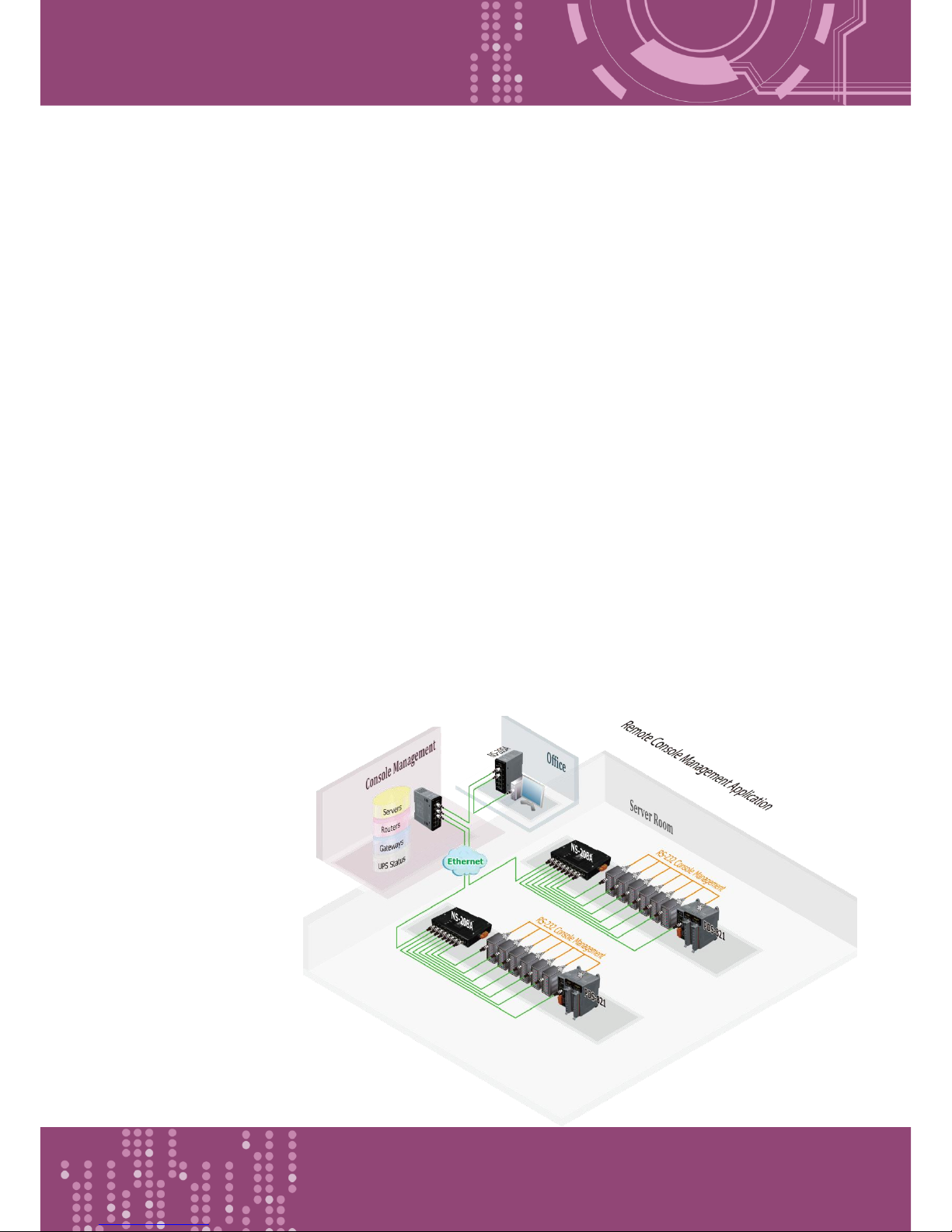
2.3 Applications
Factory Automation
Building Automation
Home Automation
Page 14
Programmable Device Server with I/O Expansion Slot(s)
PDS-8x1 Series User Manual, Version 1.1.2, Apr. 2015 - 14 -
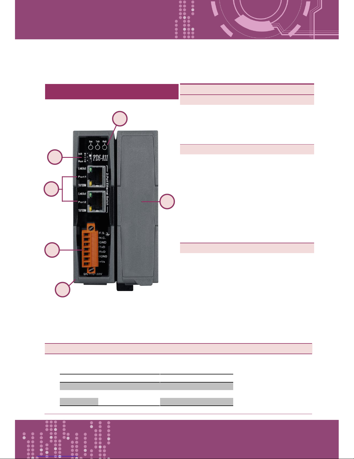
2.4 Appearance
5.
LED indicator
Once power is supplied to the PDS-8x1 controller, the system LED indicator will illuminate. An
overview of the LED functions is given below:
Name
Function
LED Behavior
Sys
Running Firmware
ON (Red)
TxD
Serial Port Busy
Flashing (Yellow)
RxD
Flashing (Green)
Front View
1.
Robust Insulated and Fire-retardant Case
2.
COM1: RS-232
For more detailed information regarding
the pin assignments for the COM1 ports,
refer to Section 2.6.1.
3.
2-Port 10/100 Base-TX Ethernet Switch
The PDS-8x1 controller are equipped with
two RJ-45 jack that is used as the 10/100
Base-TX Ethernet port and features
networking capability. When an Ethernet
link is detected and an Ethernet packet is
received, the Link/Act LED (Green)
indicator and the 10/100 M LED (Yellow)
indicator will be illuminated.
4.
I/O Expansion Slots
The PDS-811 has one I/O expansion slot,
while PDS-821 has two I/O expansion slots
that can be used to attach various 2- or 4-
port serial communication modules.
Therefore, a maximum of 4 serial ports
can be installed on the PDS-811 or a
maximum of 8 serial ports can be installed
on the PDS-821.
1 6 5 3 4
2
Page 15

Programmable Device Server with I/O Expansion Slot(s)
PDS-8x1 Series User Manual, Version 1.1.2, Apr. 2015 - 15 -
6.
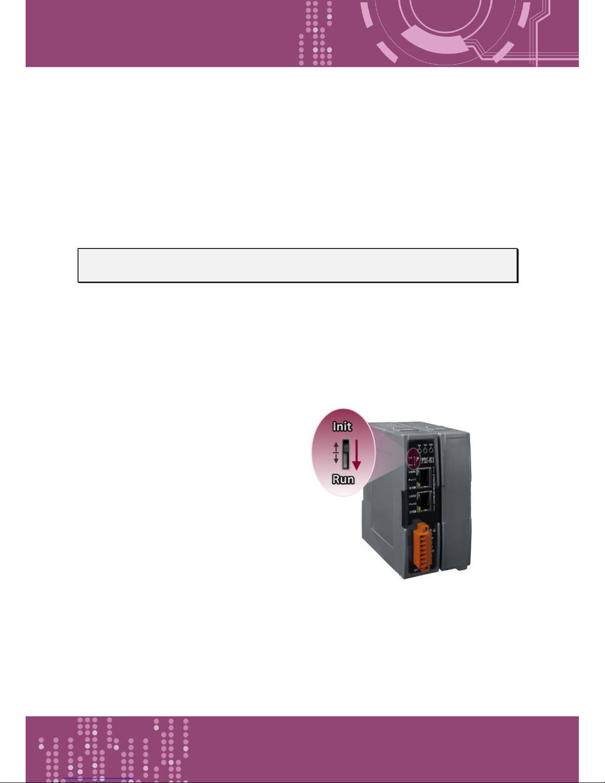
Operating Mode Switch
Init Mode: Uses factory settings and allows the firmware to be updated
Run Mode: Firmware operation mode
For PDS-8x1 controller, the operating mode switch is set to the Run position by default. In
order to update the firmware for the PDS-8x1 controller, the switch must be moved from the
Run position to the Init position. The switch must be returned to the Run position after the
update is complete.
Page 16
Programmable Device Server with I/O Expansion Slot(s)
PDS-8x1 Series User Manual, Version 1.1.2, Apr. 2015 - 16 -
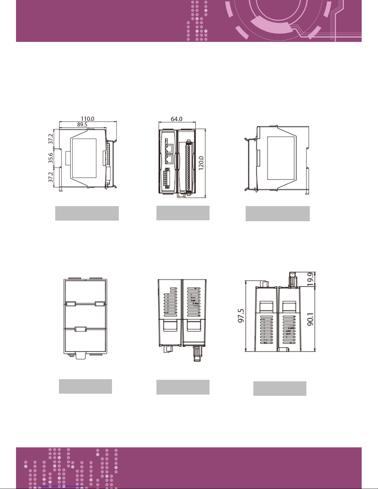
2.5 Dimensions
PDS-811 :
Units: mm
Left Side View
Front View
Right Side View
Top View
Bottom View
Rear View
Page 17
Programmable Device Server with I/O Expansion Slot(s)
PDS-8x1 Series User Manual, Version 1.1.2, Apr. 2015 - 17 -
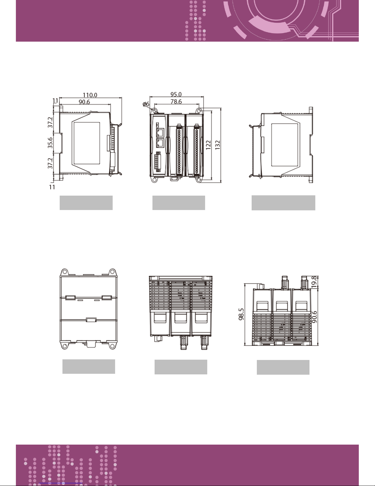
PDS-821 :
Units: mm
Front View
Rear View
Left Side View
Right Side View
Top View
Bottom View
Page 18
Programmable Device Server with I/O Expansion Slot(s)
PDS-8x1 Series User Manual, Version 1.1.2, Apr. 2015 - 18 -
2.6 Pin Assignments
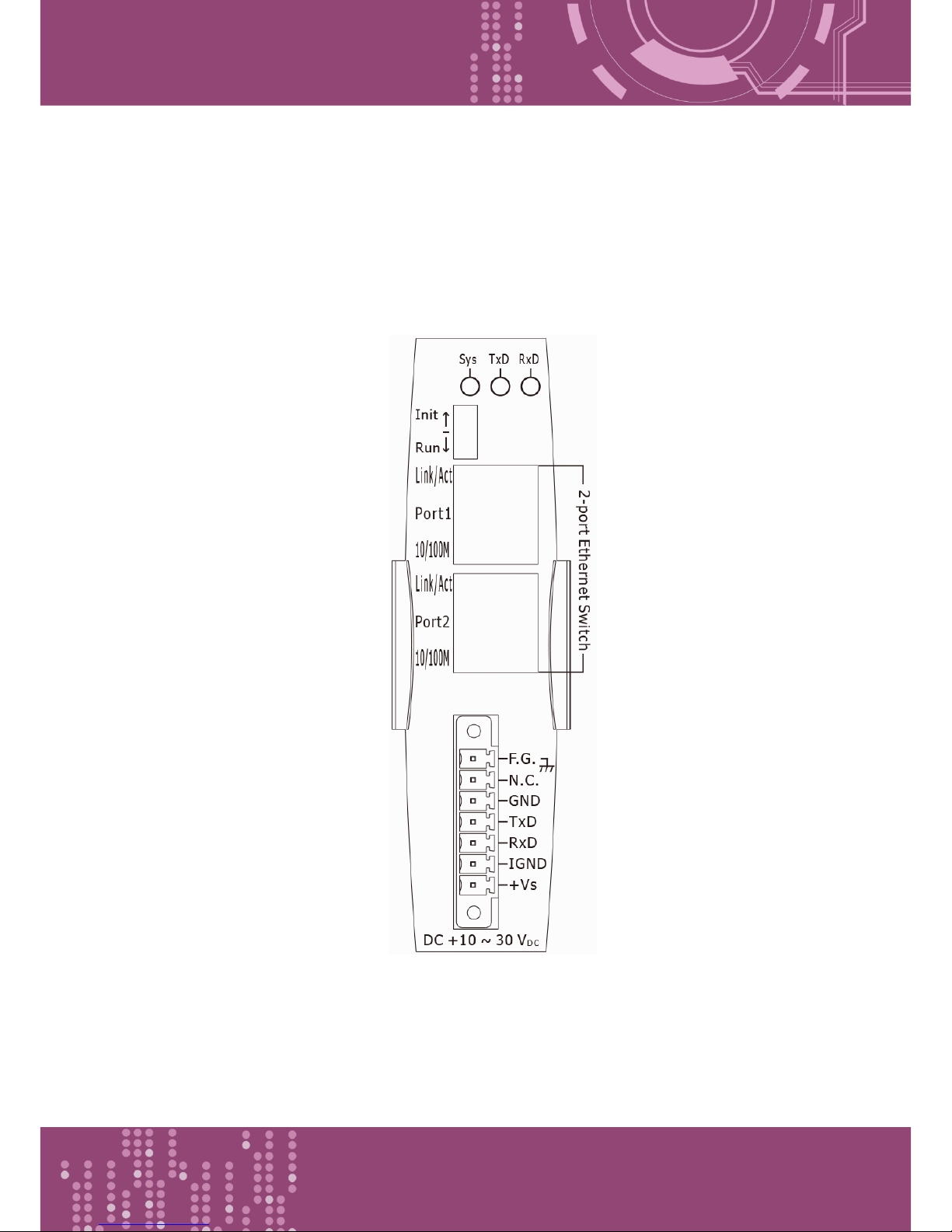
2.6.1 PDS-811 and PDS-821
Page 19
Programmable Device Server with I/O Expansion Slot(s)
PDS-8x1 Series User Manual, Version 1.1.2, Apr. 2015 - 19 -
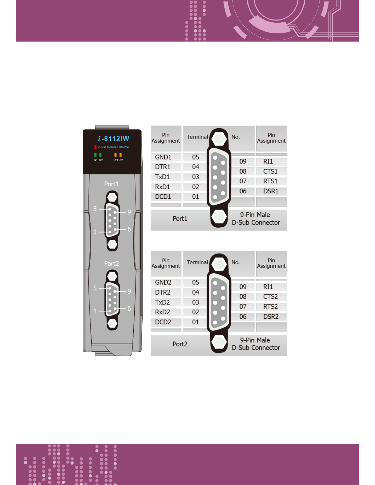
2.6.2 I-8112iW
The I-8112iW is an optional serial module that provides 2 isolated RS-232 serial ports.
Page 20
Programmable Device Server with I/O Expansion Slot(s)
PDS-8x1 Series User Manual, Version 1.1.2, Apr. 2015 - 20 -
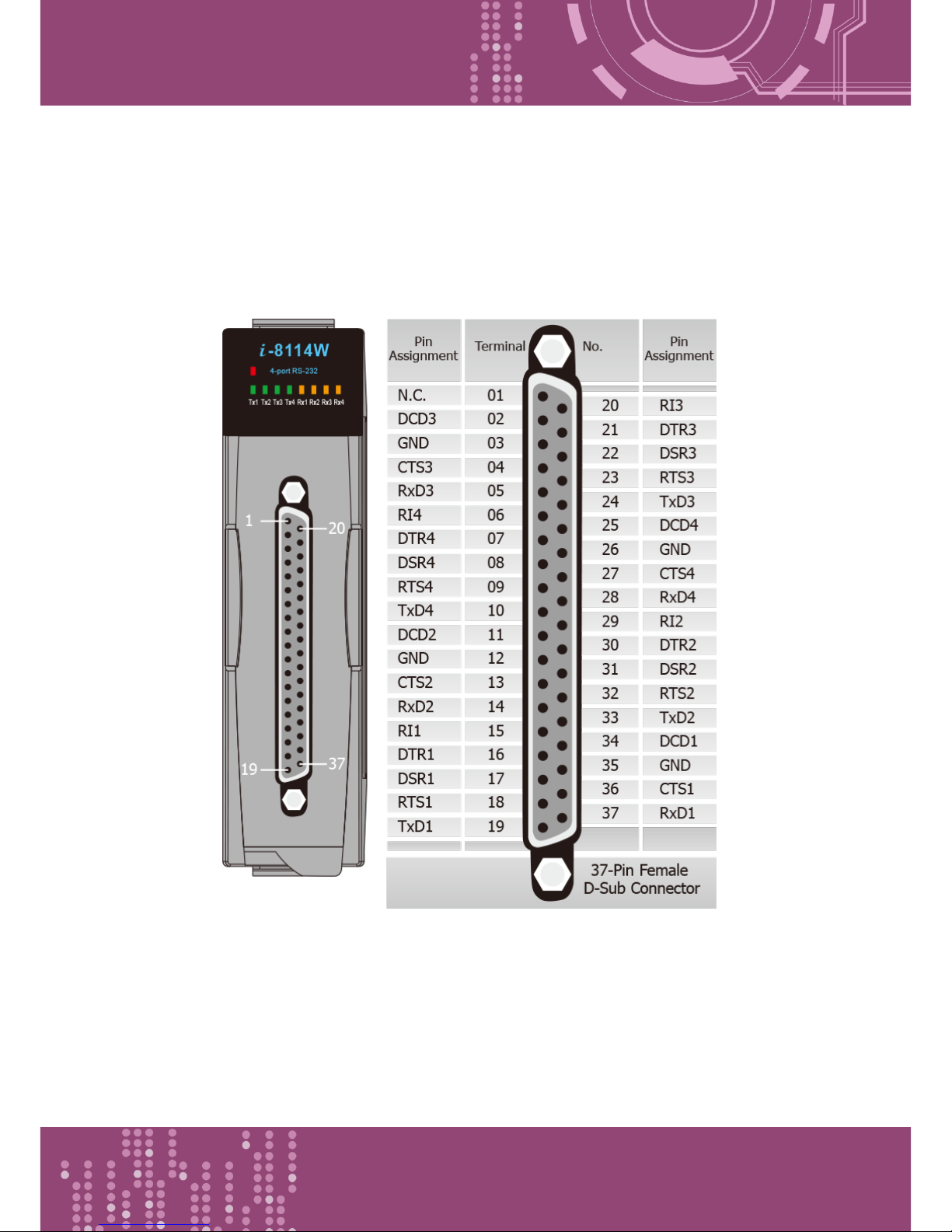
2.6.3 I-8114W
The I-8114W is an optional serial module that provides 4 non-isolated RS-232 serial ports.
Page 21
Programmable Device Server with I/O Expansion Slot(s)
PDS-8x1 Series User Manual, Version 1.1.2, Apr. 2015 - 21 -
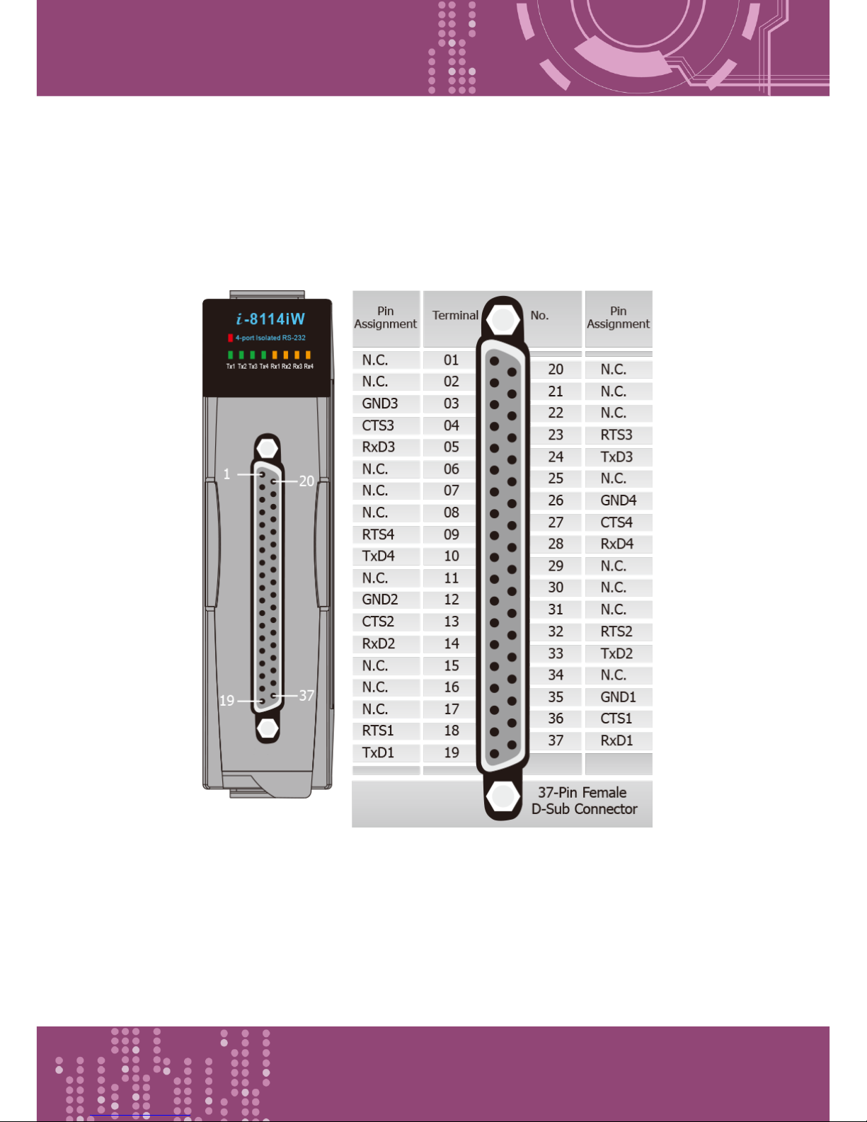
2.6.4 I-8114iW
The I-8114iW is an optional serial module that provides 4 isolated RS-232 serial ports.
Page 22
Programmable Device Server with I/O Expansion Slot(s)
PDS-8x1 Series User Manual, Version 1.1.2, Apr. 2015 - 22 -
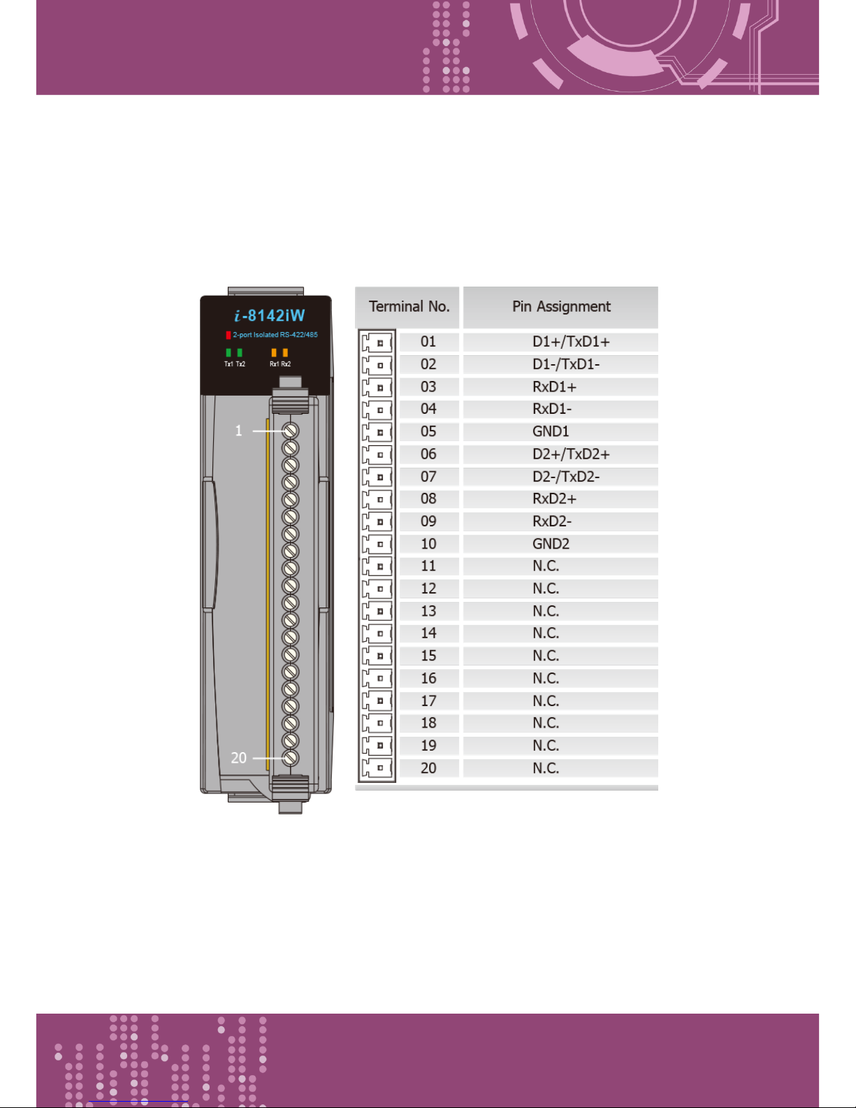
2.6.5 I-8142iW
The I-8142iW is an optional serial module that provides 2 isolated RS-422/485 serial ports.
Page 23
Programmable Device Server with I/O Expansion Slot(s)
PDS-8x1 Series User Manual, Version 1.1.2, Apr. 2015 - 23 -
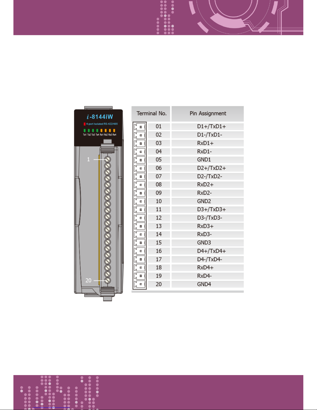
2.6.6 I-8144iW
The I-8144iW is an optional serial module that provides 4 isolated RS-422/485 serial ports.
Page 24
Programmable Device Server with I/O Expansion Slot(s)
PDS-8x1 Series User Manual, Version 1.1.2, Apr. 2015 - 24 -
2.7 Wiring Notes for RS-232/485/422 Interfaces
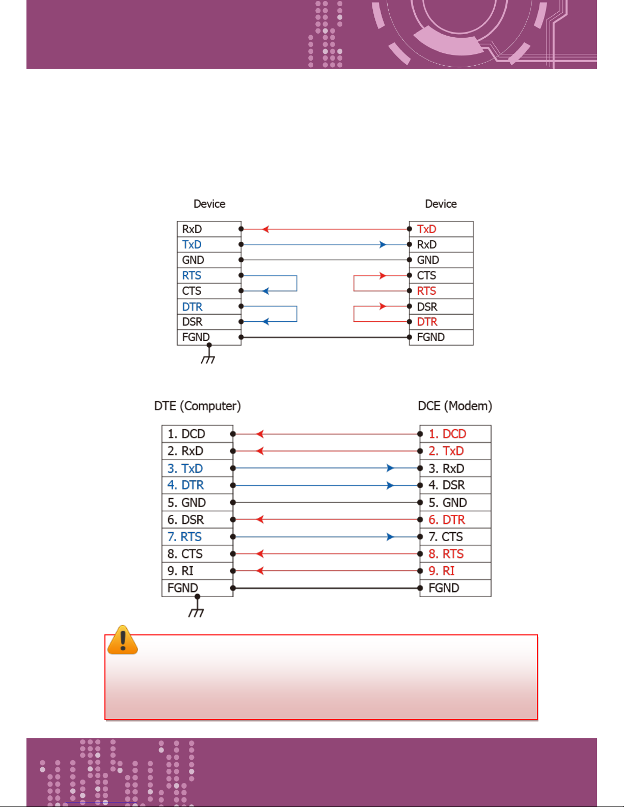
2.7.1 RS-232 Wiring
3-wire RS-232 Wiring
9-wire RS-232 Wiring
Note:
1. For 3-Wire RS-232 connections, it is recommended to short unused signals such as
RTS/CTS and DTR/DSR, since some system may still check the CTS and DSR status.
2. FGND is the frame ground that soldered to DB9 metal-shield.
Page 25
Programmable Device Server with I/O Expansion Slot(s)
PDS-8x1 Series User Manual, Version 1.1.2, Apr. 2015 - 25 -
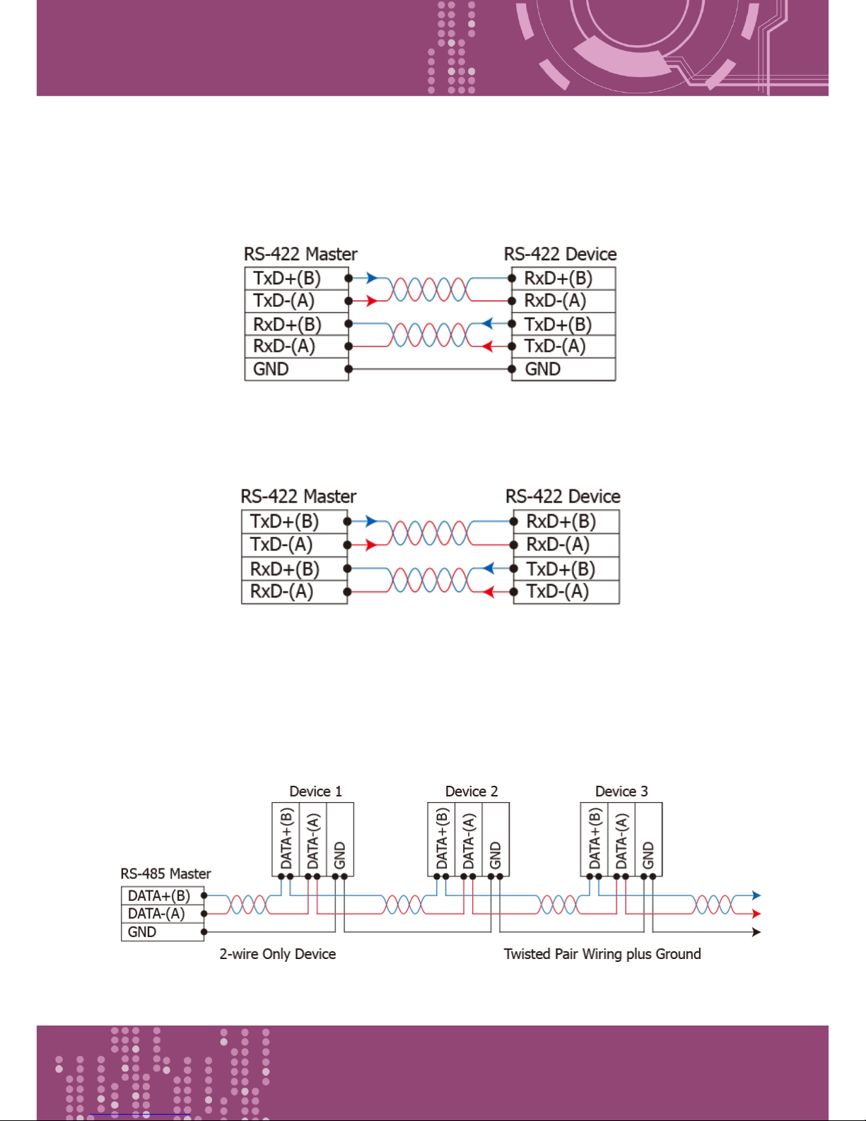
2.7.2 RS-422 Wiring
4-wire RS-422 Wiring
4-wire RS-422 Isolated Wiring
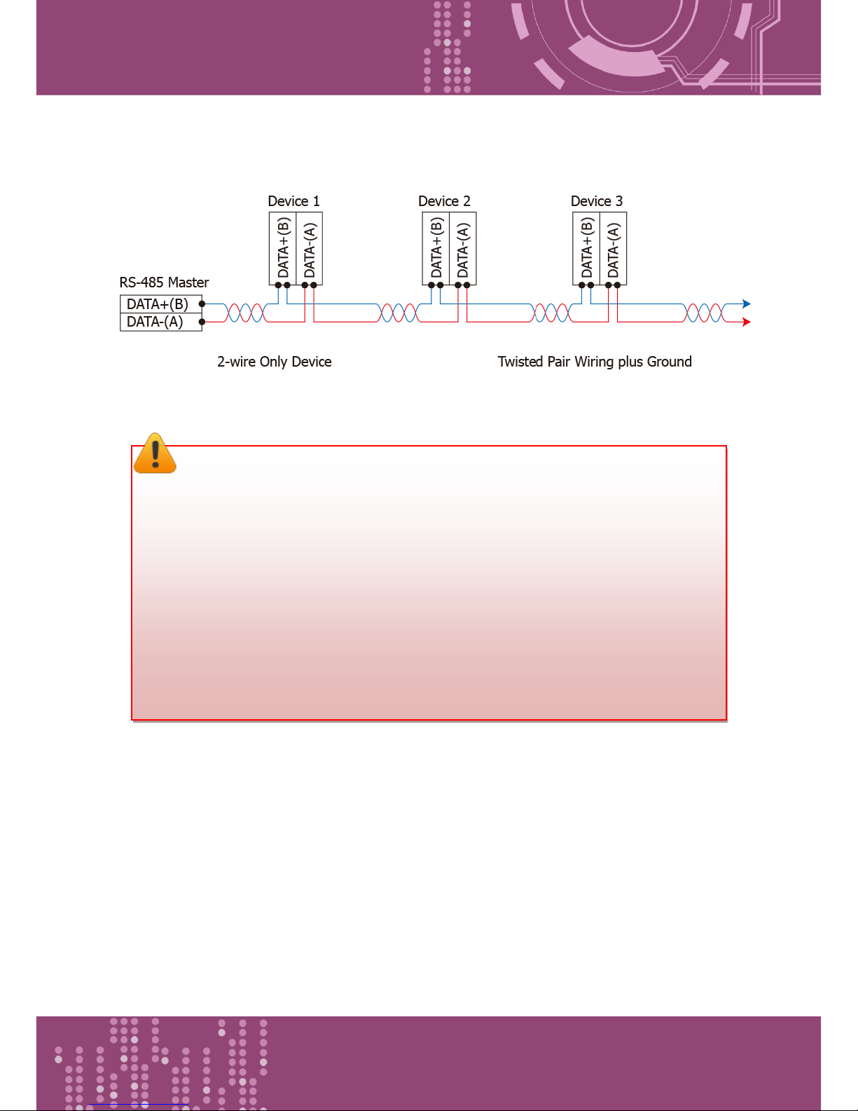
2.7.3 RS-485 Wiring
2-wire RS-485 Wiring
Page 26
Programmable Device Server with I/O Expansion Slot(s)
PDS-8x1 Series User Manual, Version 1.1.2, Apr. 2015 - 26 -
2-wire RS-485 Isolated Wiring
Note:
1. Usually, you have to connect all signal grounds of RS-422/485 devices together to
reduce common-mode voltage between devices.
2. Twisted-pair cable must be used for the DATA+/- wires.
3. Both two ends of the cable may require a termination resistor connected across the
two wires (DATA+ and DATA-). Typically 120 Ω resisters are used.
4. The Data+ and B pins are positive-voltage pins, and Data- and A pins are negative-
voltage pins in the above figure. The B/A pins may be defined in another way
depending on devices, please check it first.
Page 27
Programmable Device Server with I/O Expansion Slot(s)
PDS-8x1 Series User Manual, Version 1.1.2, Apr. 2015 - 27 -
3. Setting up the PDS-8x1 Controller
This chapter provides detailed information about the “Self-Test” process, which is used to confirm
that the PDS-8x1 controller is operating correctly. Before beginning the “Self-Test” process, the
wiring test, Ethernet configuration and VxComm utility driver installation procedures must first be
fully completed. Follow the procedure described below:
Step 1: Connect the Power Supply and the Host PC
1. Ensure that the network settings on your PC are configured correctly.
2. Ensure that the Windows firewall or any Anti-Virus firewall software is correctly
configured or temporarily disable these functions; otherwise the “Search Servers”
function in the VxComm Utility may not work as required. You may need to contact your
System Administrator for more details of how to do this.
3. Check that the Init/Run switch is in the
“Run” position.
4. Remove the I/O expansion slot cover from the PDS-8x1 controller, and then inserts a
serial module (optional) in the I/O expansion slot. (For example: I-8114iW)
Page 28
Programmable Device Server with I/O Expansion Slot(s)
PDS-8x1 Series User Manual, Version 1.1.2, Apr. 2015 - 28 -
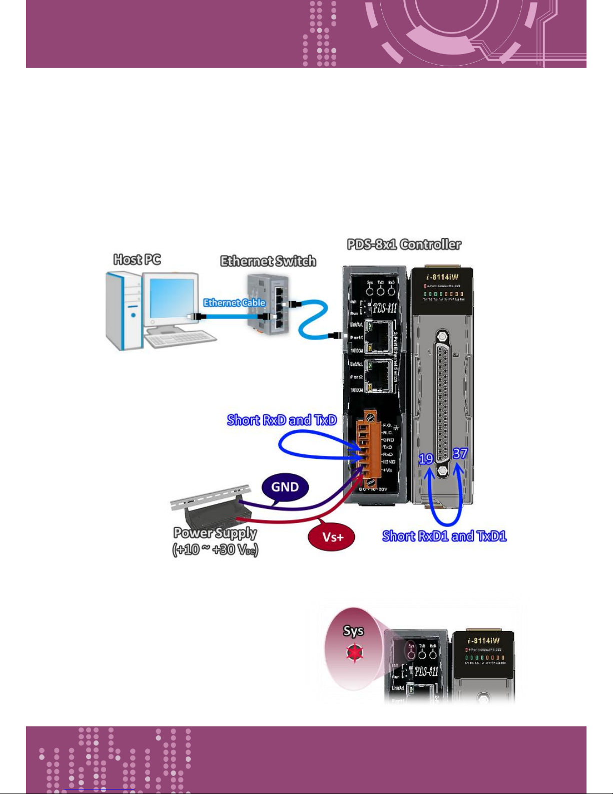
5. Connect both the PDS-8x1 and the Host computer to the same sub-network or the same
Ethernet Switch.
6. Short the RxD and TxD pins of the PDS-8x1 controller for self-test.
7. Short the TxD1 (Pin 19) and RxD1 (Pin 37) pins of the 4-Port I-8114iW module (RS-232
bus) for example of self-test.
8. Supply +24 V
DC
(+10 ~ +30 VDC) power to the PDS-8x1 controller.
The wiring diagram is as follows:
9. Verify that the System LED indicator is
flashing on the PDS-8x1 controller.
Page 29
Programmable Device Server with I/O Expansion Slot(s)
PDS-8x1 Series User Manual, Version 1.1.2, Apr. 2015 - 29 -
Step 2: Install the VxComm Utility
The VxComm Utility can be obtained from either the companion CD-ROM, the ICP DAS FTP site, or the ICP
DAS web site. The location of the install files on the CD and the download addresses are shown below:
CD:\\ NAPDOS\DRiver\VxComm_Driver\2k\
http://ftp.icpdas.com/pub/cd/8000cd/napdos/driver/vxcomm_driver/2
k/
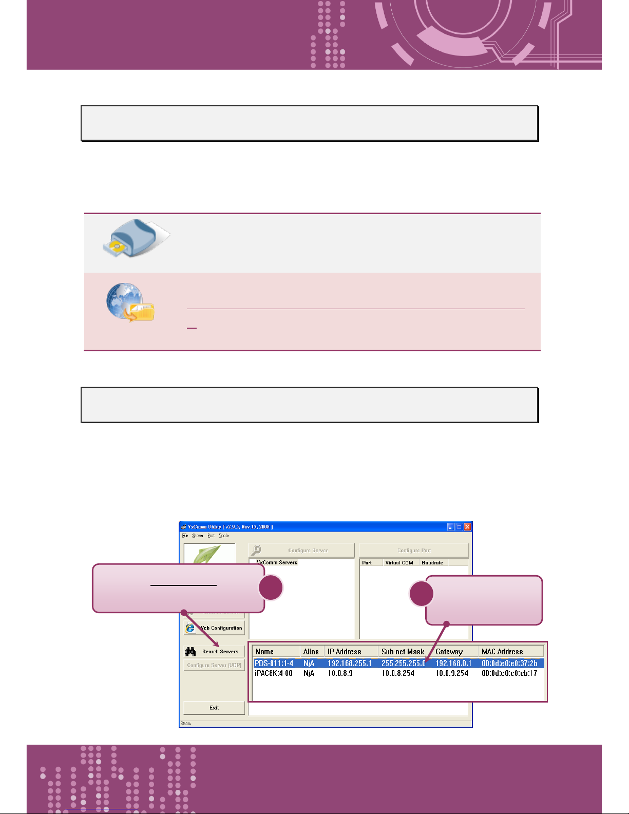
Step 3: Search for the PDS-8x1 controller on the Ethernet network
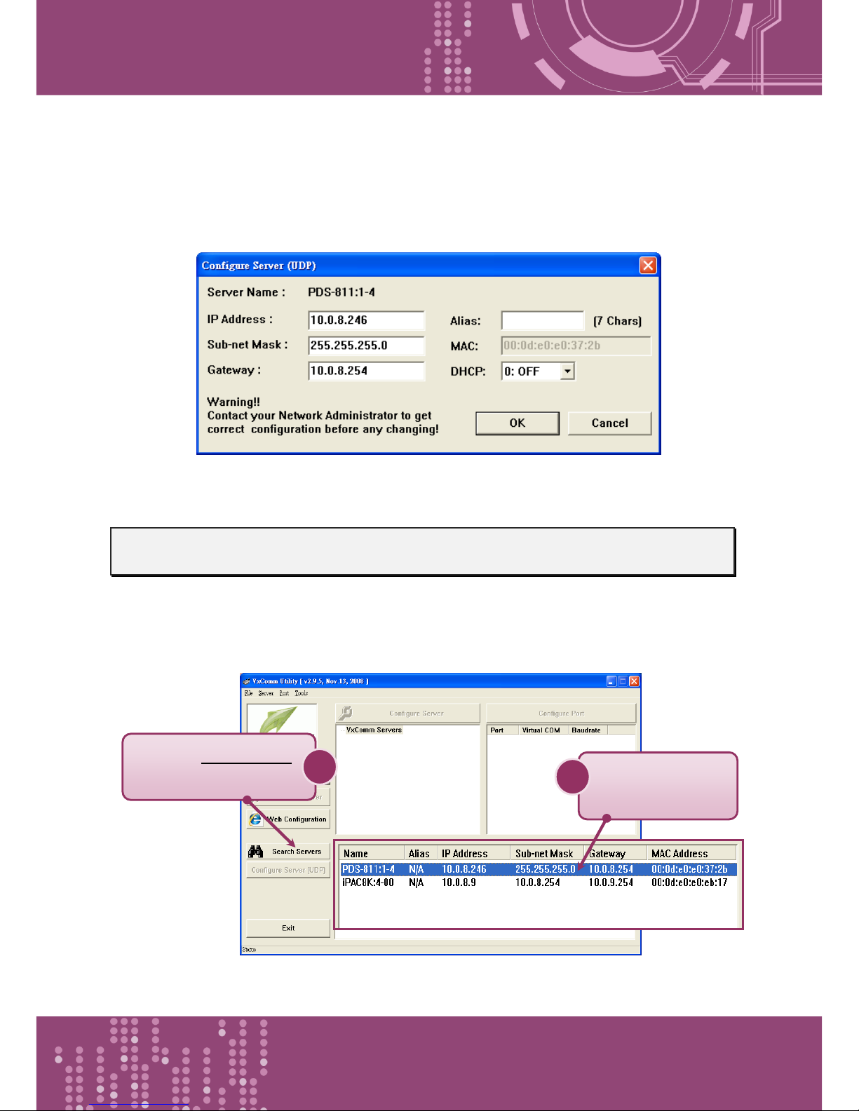
1. Open the VxComm Utility and then click the “Search Servers” button to search for the
PDS-8x1 controller.
2. Once the search process is complete, double-click the name of the PDS-8x1 controller to
open the “Configure Server” dialog box.
Click the “Search Severs”
button to search for your PDS
1
Double click the
name of your PDS
2
Page 30
Programmable Device Server with I/O Expansion Slot(s)
PDS-8x1 Series User Manual, Version 1.1.2, Apr. 2015 - 30 -
3. Enter the network settings information, including the IP, Mask and Gateway addresses,
and then click “OK” button. The new settings for the PDS-8x1 controller will take effect
within 2 seconds. If you don’t know the correct network configuration information,
contact your Network Administrator to obtain the details.
Step 4: Configuring the Virtual COM Ports
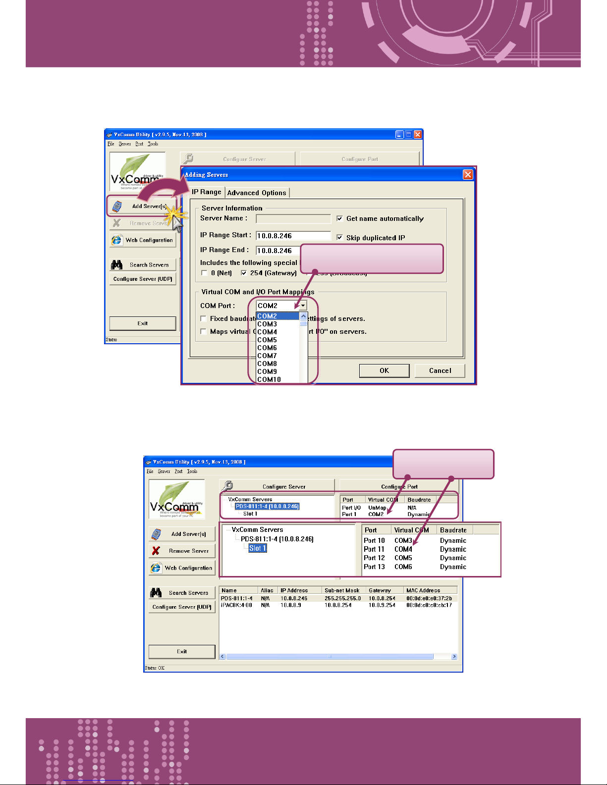
1. Wait 2 seconds and then click the “Search Servers” button again to ensure that the PDS-8x1
controller is working correctly with the new configuration.
Click the “Search Severs”
button
1
Click your PDS on
the list
2
Page 31
Programmable Device Server with I/O Expansion Slot(s)
PDS-8x1 Series User Manual, Version 1.1.2, Apr. 2015 - 31 -
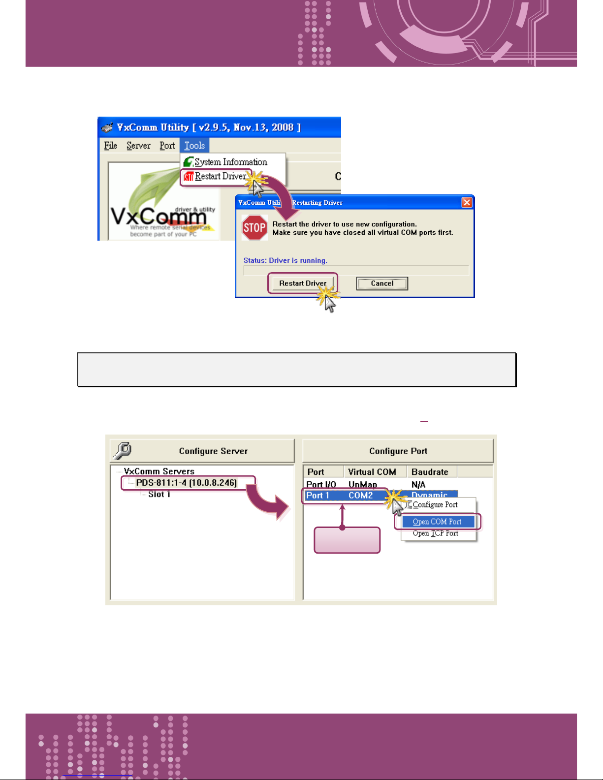
2. Click the “Add Server*s+” button. Assign a COM Port number and click “OK” to save your
settings.
3. Click on PDS-8x1 controller name or slot that your module plugged in, and then check the
virtual COM port mappings on the PC.
Assign a COM Port number
Check COM Port
Page 32
Programmable Device Server with I/O Expansion Slot(s)
PDS-8x1 Series User Manual, Version 1.1.2, Apr. 2015 - 32 -
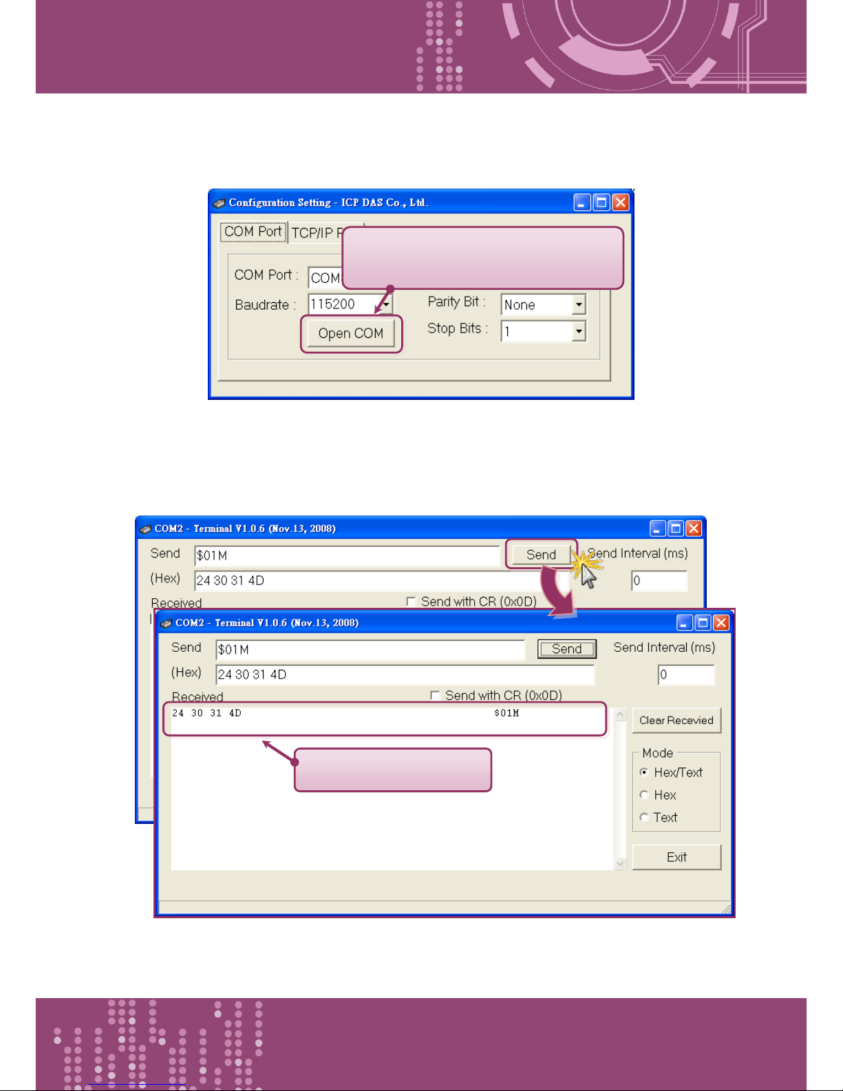
4. Click “Tools” “Restart Driver”, and then click the “Restart Driver” button.
Step 5: Testing your PDS-8x1 controller
1. Click on PDS-8x1 controller name and right click Port 1 then choose the “Open COM Port” item.
Right Click
Page 33
Programmable Device Server with I/O Expansion Slot(s)
PDS-8x1 Series User Manual, Version 1.1.2, Apr. 2015 - 33 -
2. Check that the configuration of the COM Port is correct and then click the “Open COM” button.
3. Type a string in the send field then click the “Send” button. If a response is received, it will be
displayed in the received field.
Check that the configuration is correct
and then click the “Open COM” button
The response is displayed
Page 34
Programmable Device Server with I/O Expansion Slot(s)
PDS-8x1 Series User Manual, Version 1.1.2, Apr. 2015 - 34 -
Step 5: Testing your Serial Modules (Optional)
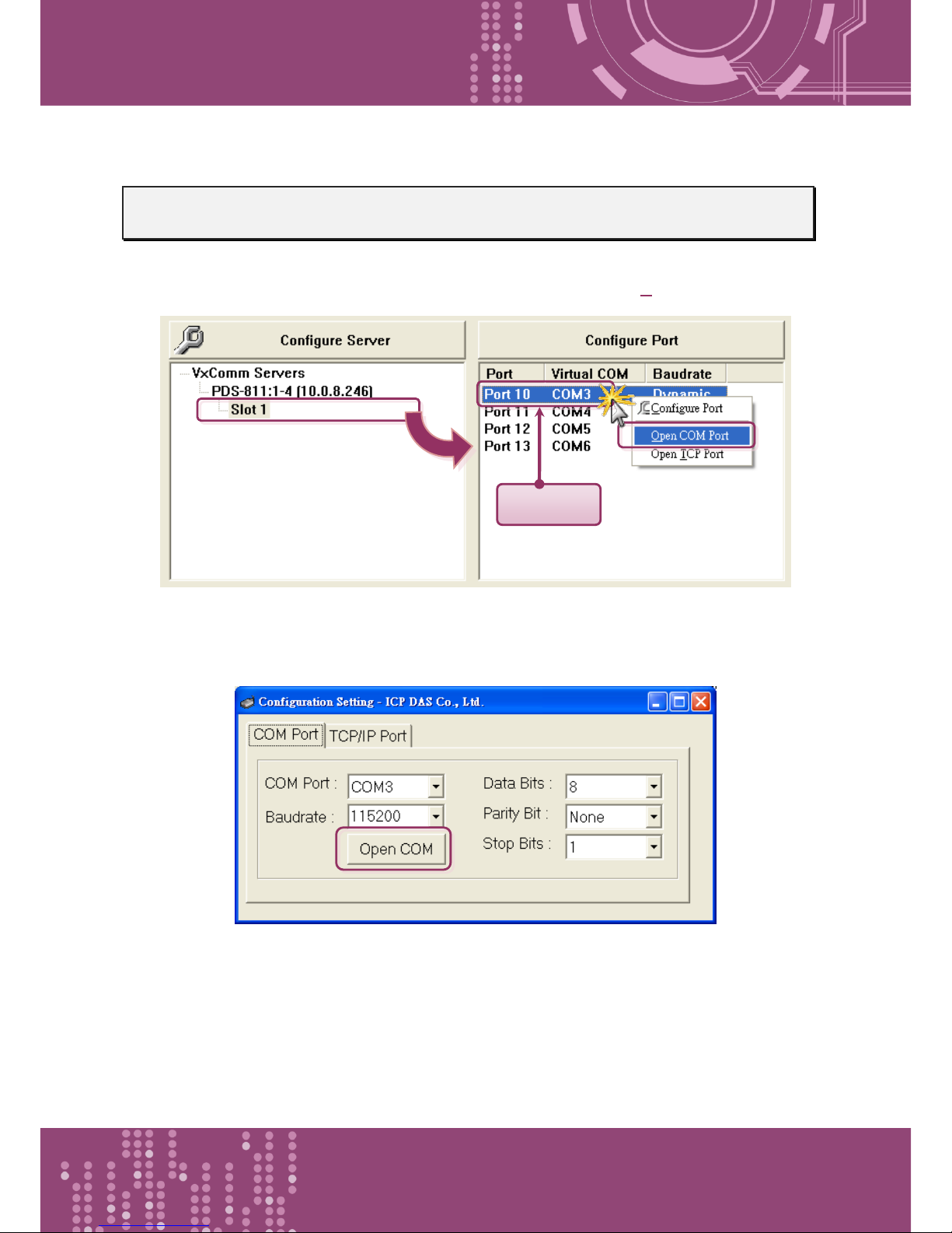
1. Click on serial modules (Slot) and right click Port 10 then choose the “Open COM Port” item.
2. Check that the configuration of the COM Port is correct and then click the “Open COM” button.
Right Click
Page 35
Programmable Device Server with I/O Expansion Slot(s)
PDS-8x1 Series User Manual, Version 1.1.2, Apr. 2015 - 35 -
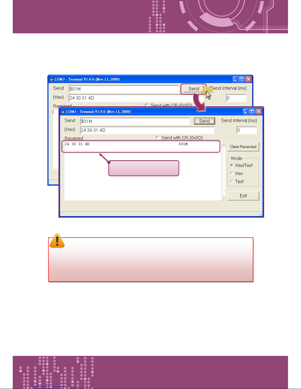
3. Type a string in the send field then click the “Send” button. If a response is received, it will be
displayed in the received field.
4. If the test is successful, then your COM port program should now be able to work with this
Virtual COM Port.
The response is displayed
Note:
While using RS-485 modules (e.g. I-8144iW), you should wire the Data1+ with Data2+
signals, and wire the Data1- with Data2- signals for self-test. Then open the first two
COM ports, send data to one and receive data from the other.
Page 36
Programmable Device Server with I/O Expansion Slot(s)
PDS-8x1 Series User Manual, Version 1.1.2, Apr. 2015 - 36 -
4. Web Configuration
Once the PDS-8x1 controller has been correctly configured and is functioning on the network
normally, the configuration details can be retrieved or modified using either the VxComm Utility or
a standard web browser.
4.1 Logging in to the PDS-8x1 Web Server
The embedded PDS-8x1 controller web server can be accessed from any computer that has an
Internet connection.
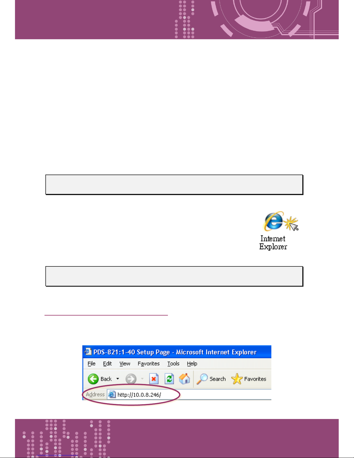
Step 1: Open a new browser window.
Open a web browser, for example, Google Chrome, Firefox or Internet
Explorer, which are reliable and popular Internet browsers that can be used
to configure PDS-8x1 controller.
Step 2: Enter the URL for the PDS-8x1 web server
Ensure that you have correctly configured the network settings for the PDS-8x1 controller (refer to
Chapter 3 Setting up the PDS-8x1 Controller for detailed instructions), and then enter the URL
address of the PDS-8x1 in the address bar of the browser or click the “Web” button in the VxComm
Utility to log in to the web configuration pages.
Page 37
Programmable Device Server with I/O Expansion Slot(s)
PDS-8x1 Series User Manual, Version 1.1.2, Apr. 2015 - 37 -
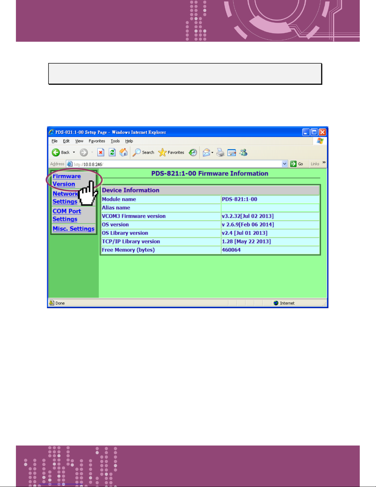
Step 3: Log in to the PDS-8x1 Web Server
After logging into the PDS-8x1 web server, the main page will be shows firmware information of the
PDS-8x1 controller.
Page 38
Programmable Device Server with I/O Expansion Slot(s)
PDS-8x1 Series User Manual, Version 1.1.2, Apr. 2015 - 38 -
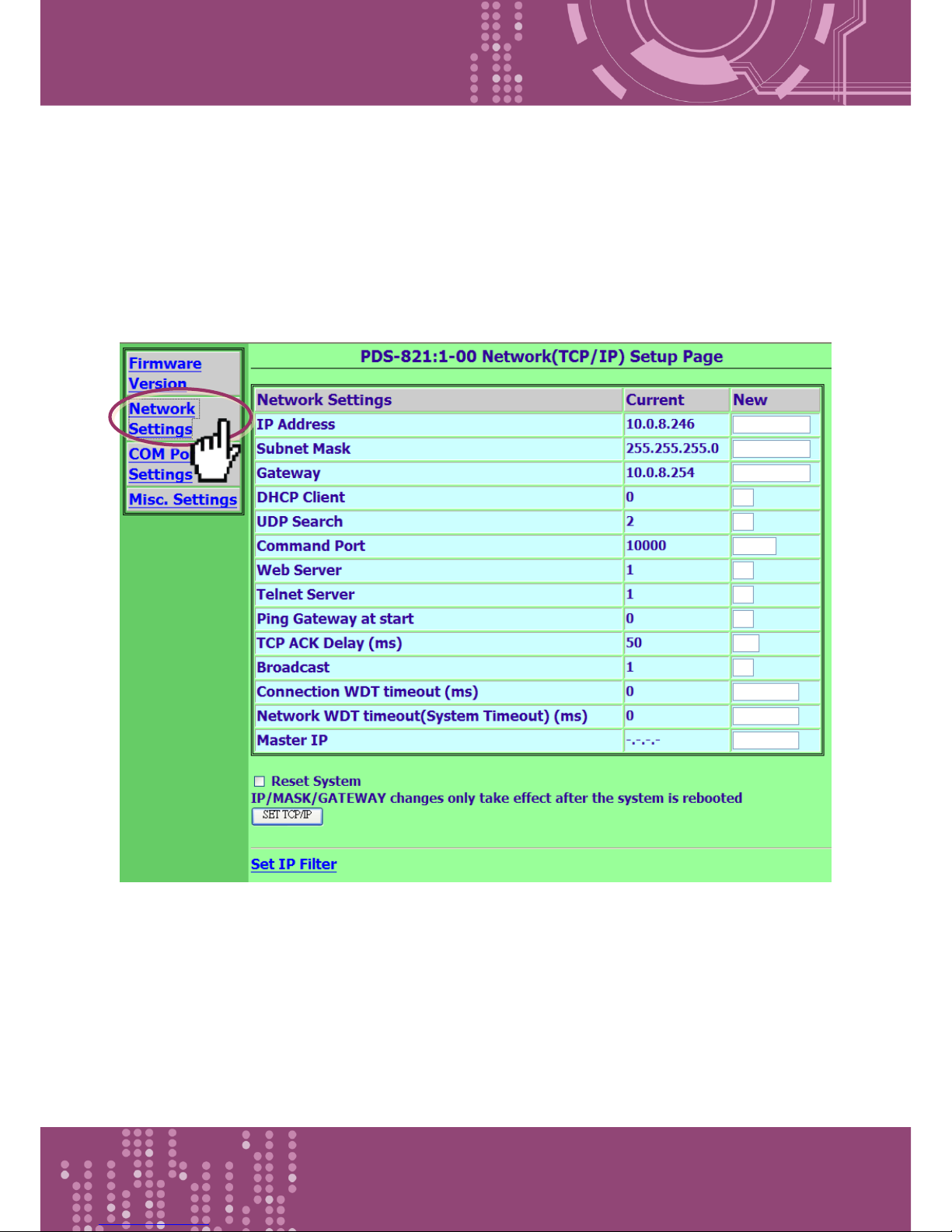
4.2 Network Setting
The Network Settings section provides information related to most important network settings for
the PDS-8x1 controller, including the IP Address, Subnet Mask and Default Gateway values, etc. If
they do not match, the PDS-8x1 controller will not operate correctly. If the settings are changed
while the module is operating, any connection currently in use will be lost and an error will occur.
Page 39

Programmable Device Server with I/O Expansion Slot(s)
PDS-8x1 Series User Manual, Version 1.1.2, Apr. 2015 - 39 -
The following is an overview of the parameters contained in the Network Settings section:
Item
Description
Default
IP Address
If no DHCP server is installed on the network, the network settings
can be configured manually.
Subnet Mask
This parameter is used to assign the subnet mask for the PDS-8x1
controller. The subnet mask indicates which portion of the IP address
is used to identify the local network or subnet.
Gateway
This parameter is used to assign the IP Address of the Gateway to be
used by the PDS-8x1 controller. A Gateway (or router) is a device that
is used to connect an individual network to one or more additional
networks.
DHCP Client
This parameter is used to enable or disable DHCP Client configuration
function. It is recommended that the DHCP Client setting is kept as
disabled, and using static network settings. This ensures your PDS-
8x1 controller always using a fixed IP address, and you don’t need to
configure the virtual COM mappings again and again.
0 = Disabled, 1 = Enabled
UDP Search
This parameter is used to enable or disable UDP
Search function.
0 = Disabled
1 = Enabled
2 = Enable the UDP Search function until another
client is connected.
By keeping the UDP search setting as 2, the PDS-8x1
controller loading will be reduced. The VxComm
Utility will not be able to search for this module until
this module’s clients are all disconnected.
2
Command Port
This parameter is used to configure the TCP Command
Port to a custom value depending on your
requirement. Note that if the TCP Command Port
configuration setting is completed, the TCP port of
serial port will be change, as follows:
COM1= TCP Command Port + 1
COM2= TCP Command Port + 2 …., and so on.
The default TCP Command Port is 10000. Thus, the
serial COM port1/port2 is 10001/10002, and so on.
10000
Page 40

Programmable Device Server with I/O Expansion Slot(s)
PDS-8x1 Series User Manual, Version 1.1.2, Apr. 2015 - 40 -
Web Server
This parameter is used to enable or disable Web
Server function.
0 = Disabled, 1 = Enabled
1
Telnet Server
This parameter is used to enable or disable Telnet
Server function.
0 = Disabled, 1 = Enabled
1
Ping Gateway at start
If the setting is 1 (enabled), the PDS-8x1 controller will
send a ping packet to the gateway during the power-
on stage. It is used to inform the gateway that a PDS-
8x1 controller (itself) has joined the network.
0 = Disabled, 1 = Enabled
0
(Disabled)
TCP ACK Delay (ms)
PDS-8x1 controller does not want to send an empty
ACK followed by a TCP data packet 1ms later, every
time. So it delays a little (TCP ACK Delay), and then
can combine the ACK and data packet into one. This
efficiency reduces the number of packets and
reduces network loadings.
50 ms
Broadcast
This parameter is used to receive or reject UDP
broadcast packets.
1 = receive UDP broadcast packets
0 = reject UDP broadcast packets
1
Connection WDT
timeout (ms)
If the PDS-8x1 controller does not receive any data
from a client PC within the period of the “Connection
WDT timeout”, the module will close the connection
to the client.
0 = Disabled, Min. setting value = 10000
0
(Disabled)
Network WDT timeout
(System Timeout) (ms)
If the PDS-8x1 controller does not receive any data
from any of the clients within the period of the
“Network WDT timeout”, the module will reboot
itself.
This setting is the same as “SystemTimeout” setting
(unit: ms) on Console/Telnet command, and is the
same as “/STxxx” in command line parameter (unit:
seconds).
0
(Disabled)
Page 41

Programmable Device Server with I/O Expansion Slot(s)
PDS-8x1 Series User Manual, Version 1.1.2, Apr. 2015 - 41 -
When user uses “config=RESET” Console/Telnet
command to clear the EEPROM, the “Network WDT
timeout” (SystemTimeout, /ST) setting will also be
cleared to 0.
Users have to configure this setting again by
“SystemTimeout” Console/Telnet command.
0 = Disabled, Min. setting value = 30000
Master IP
If the Master IP is set, only the client using Master IP
can change the COM Port configuration. It is to
prevent the COM Port configuration changed by
other clients.
empty
Reset System
If the “Reset System” option is checked, the PDS-8x1 controller will
reboot itself after the saving operation is complete, otherwise the
original settings will still be valid until the next power-on.
SET TCP/IP
Click this button to save the revised settings to the PDS-8x1
controller.
Page 42
Programmable Device Server with I/O Expansion Slot(s)
PDS-8x1 Series User Manual, Version 1.1.2, Apr. 2015 - 42 -
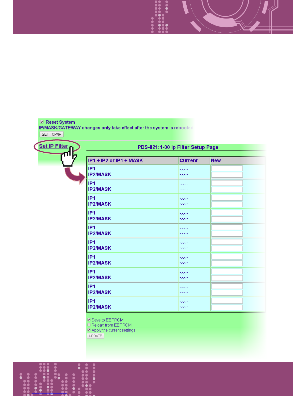
4.2.1 IP Filter Setting
The IP filter setting limits which client PCs are able to link to the PDS-8x1 controller via specific IP
addresses. When one or more IP addresses are set in the filter table, only client PCs where the IP
address is included in the range listed of the filter table will be able to connect to the PDS-8x1
controller. Any requests from other PCs will be rejected.
Page 43
Programmable Device Server with I/O Expansion Slot(s)
PDS-8x1 Series User Manual, Version 1.1.2, Apr. 2015 - 43 -
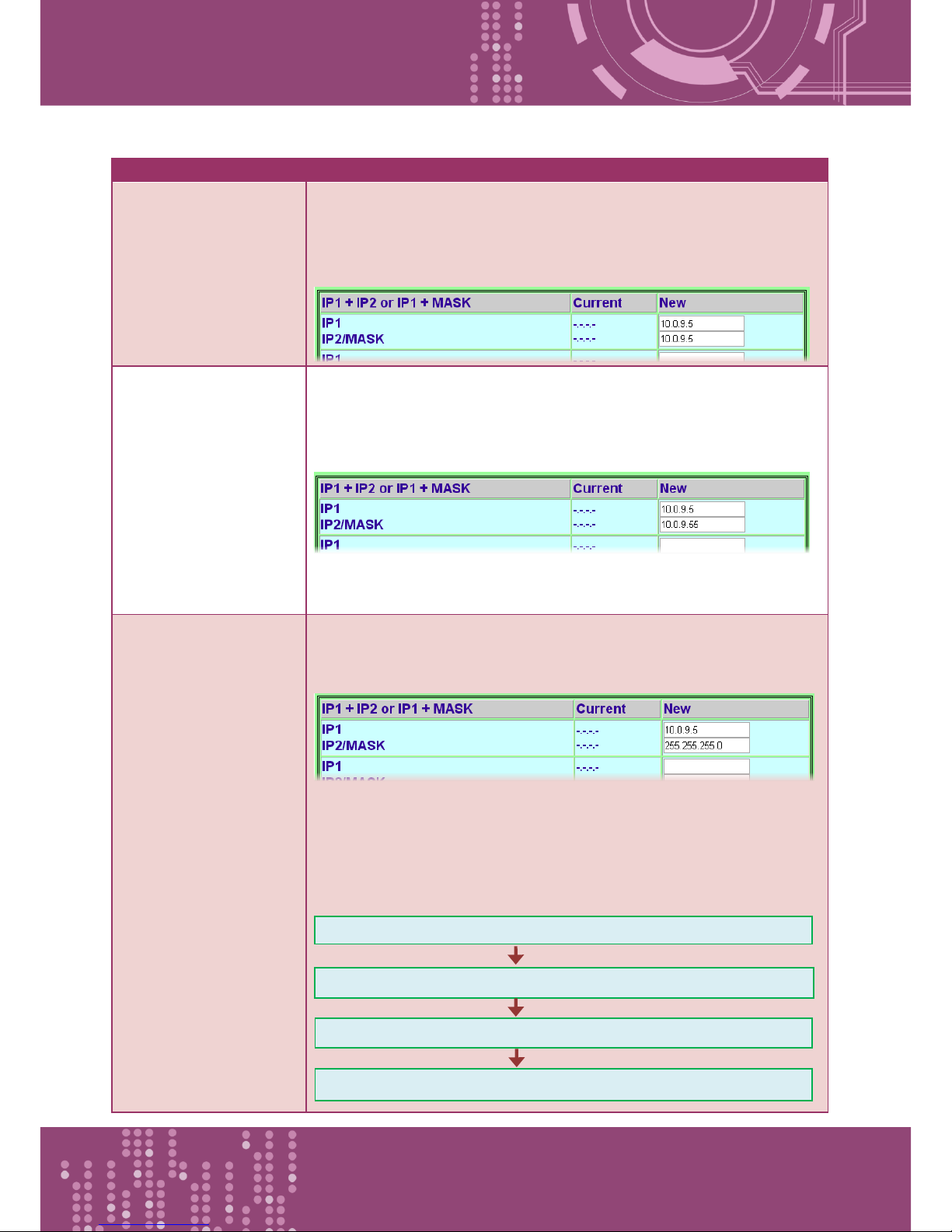
The following is an overview of the parameters contained in the IP Filter Setup Page section:
Item
Description
Set IP1 only
Set a single IP address, the IP address entered in the “IP1” and
“IP2/MASK” text fields will be the same, as the image below shows.
Only clients who’s IP address is included in the filter table are able to
connect to the PDS-8x1 controller.
Set IP1 + IP2
Set a range of IP address as a starting and ending point. The initial IP
address must be entered in the “IP1” text field and final IP address
must be entered in the “IP2/MASK” text field, as the image below
shows.
This allows clients who’s IP address is included in the range of
10.0.9.5 to 10.0.9.55 are able to connect to the PDS-8x1 controller.
Set IP1 + Mask
Set the IP Filter (Available IP) range, the IP address must be entered in
the “IP1” text field and Mask address must be entered in the
“IP2/MASK” text field, as the image below shows.
This allows clients who’s IP address is included in the range of
10.0.9.0 to 10.0.9.255 are able to connect to the PDS-8x1 controller.
Note that how to get the IP address range 10.0.9.0 to 10.0.9.255?
It’s calculated as follows:
Formula: (IP1 & MASK) to (IP1 & Mask) + (~MASK)
(10.0.9.5 & 255.255.255.0) to (10.0.9.5 & 255.255.255.0) + (0.0.0.255)
10.0.9.0 to 10.0.9.255
(10.0.9.0) to (10.0.9.0) + (0.0.0.255)
Page 44
Programmable Device Server with I/O Expansion Slot(s)
PDS-8x1 Series User Manual, Version 1.1.2, Apr. 2015 - 44 -
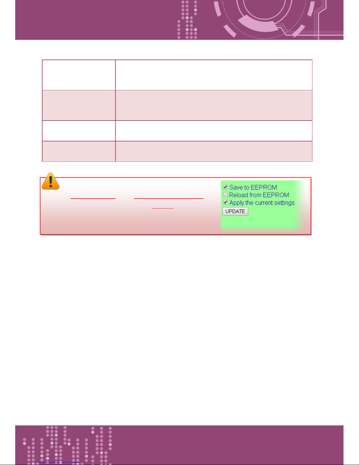
Save to EEPROM
If the “UPDATE” button is clicked with checking “Save to EEPROM”
option, the new settings will be saved to the PDS-8x1 controller only
and the new settings will be valid after the next power-on.
Reload from EEPROM
If the “UPDATE” button is clicked with checking “Reload from
EEPROM” option, PDS-8x1 controller can apply the settings from
EEPROM immediately.
Apply the current
settings
If the “Apply the current settings” checked when the “UPDATE”
button is clicked, the new settings will be valid immediately.
UPDATE
Click this button to save the revised settings to the PDS-8x1
controller.
Note: After configuring IP filter settings, please confirm
that the “Save to EEPROM” and “Apply the current settings”
option are checked, and then click the “UPDATE” button.
Page 45
Programmable Device Server with I/O Expansion Slot(s)
PDS-8x1 Series User Manual, Version 1.1.2, Apr. 2015 - 45 -
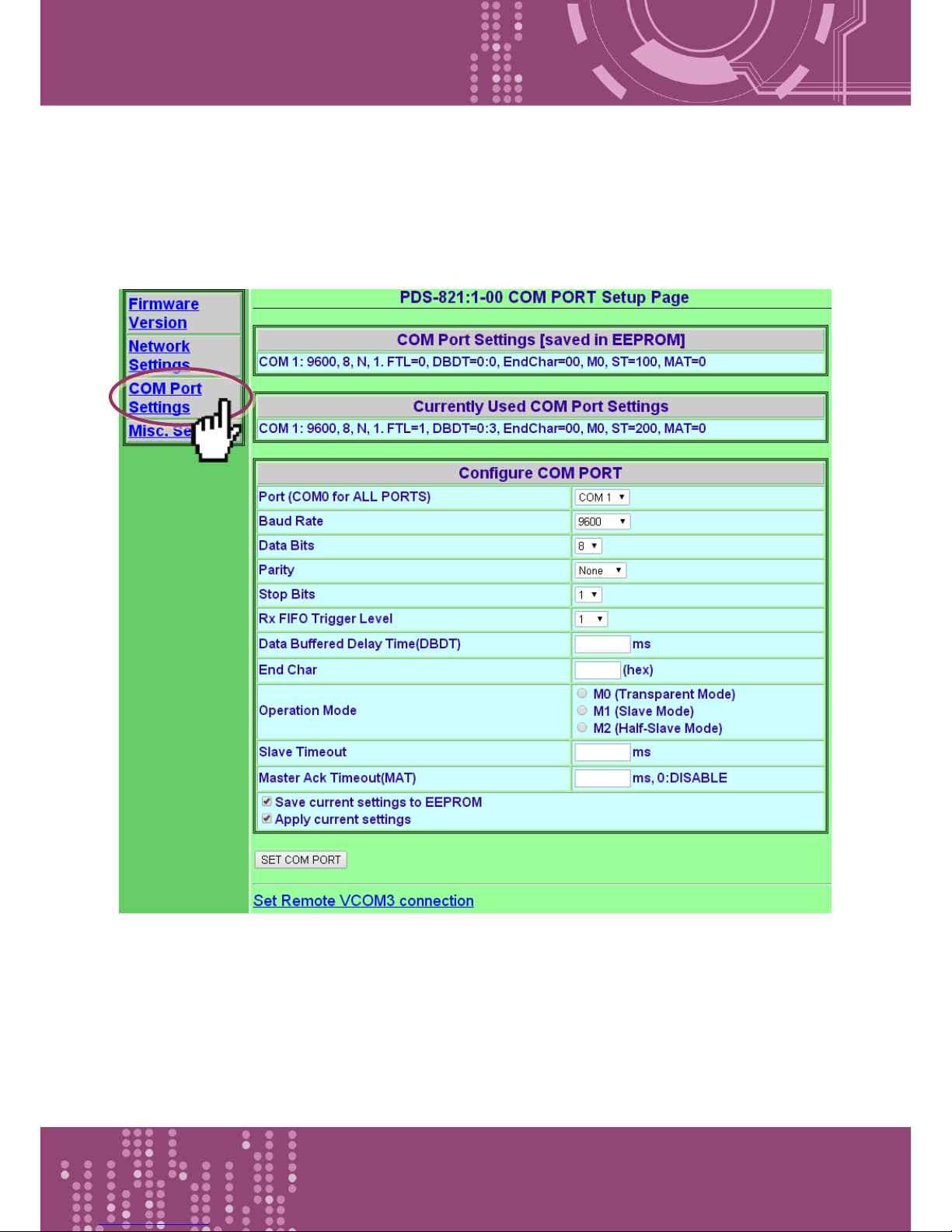
4.3 COM Port Settings
The COM Port Settings section provides functions allowing items such as baud rate, data format,
data transmission mode and pair-connection settings, etc. to be configured.
Page 46
Programmable Device Server with I/O Expansion Slot(s)
PDS-8x1 Series User Manual, Version 1.1.2, Apr. 2015 - 46 -
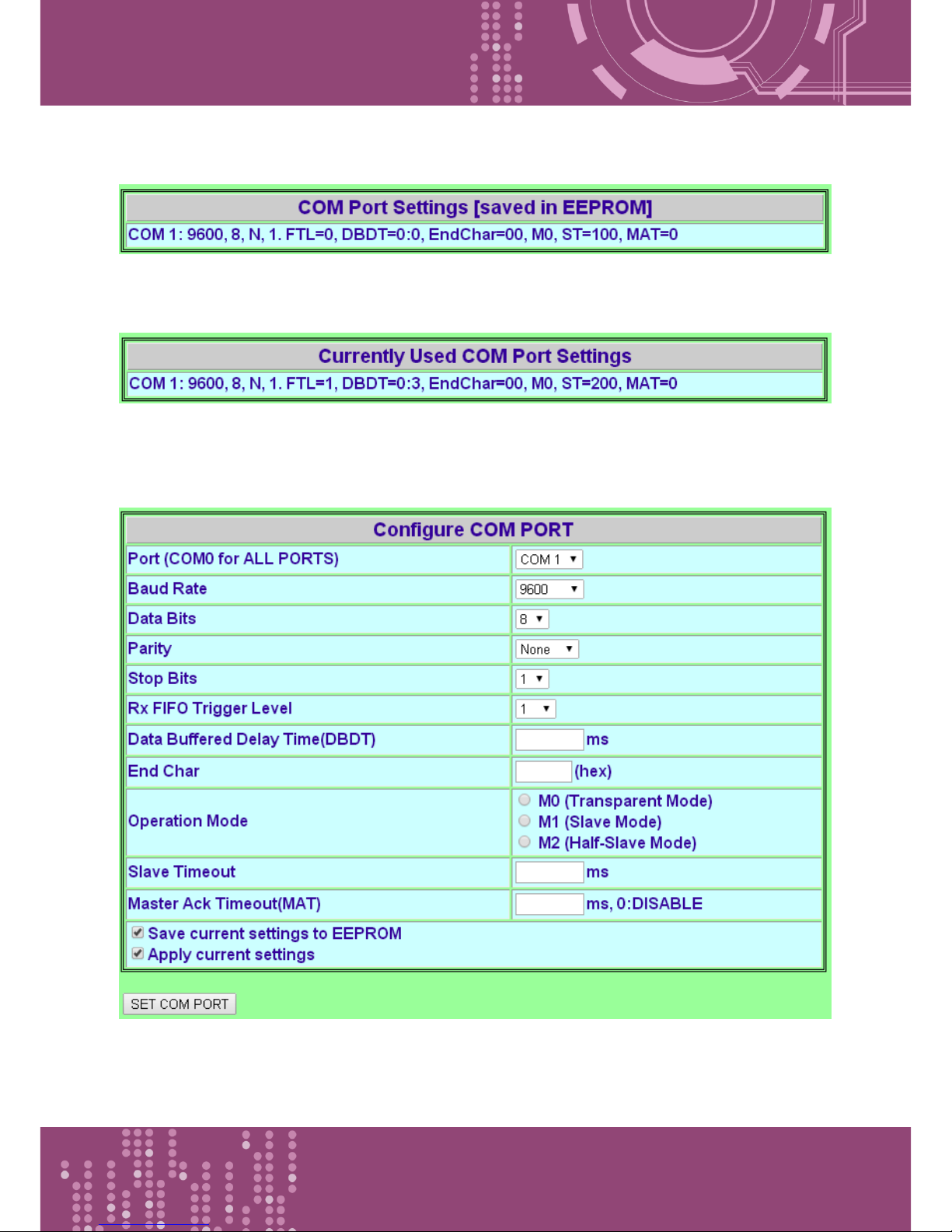
The COM Port Settings list is saved in the EEPROM on the PDS-8x1 controller.
The Currently Used COM Port Settings list.
The COM Port Settings area.
Page 47

Programmable Device Server with I/O Expansion Slot(s)
PDS-8x1 Series User Manual, Version 1.1.2, Apr. 2015 - 47 -
The following is an overview of the parameters contained in the COM Port Settings section:
Item
Description
Default
Port (COM0 for ALL
PORTS)
The COM Port number on the PDS-8x1 controller.
COM1
Baud Rate
This parameter is used to set the Baud Rate for the COM
ports.
9600
Data Bits
This parameter is used to set the Data Size for the COM
ports.
8
Parity
This parameter is used to set the Parity for the COM ports.
None
Stop Bits
This parameter is used to set the Stop Bits for the COM
ports.
1
Rx FIFO Trigger Level
This option is used to set the number of characters that
the COM Port can receive at once time, the PDS-8x1
controller will move the data from the COM Port FIFO to
the PDS-8x1 controller. If the amount of data transferred
is large and uses a transfer speed (115200 bps), setting a
smaller value is helpful in preventing data loss.
1
Data Buffered Delay
Time (DBDT)
When the COM port does not receive data from devices
connected over the period of DBDT setting, the PDS-8x1
controller will determine that the data transfer is over
and return to process next tasks.
0
End Char
The PDS-8x1 controller outputs an Ethernet packet
immediately after the ending-chars pattern is identified
from the incoming serial data.
0
(Disabled)
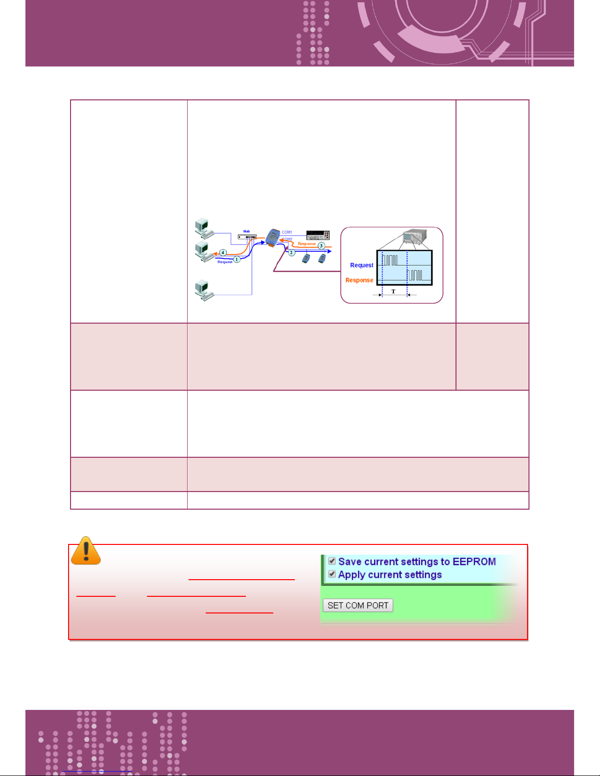
Operation Mode
M0: Transparent Mode (Multi-echo mode)
M1: Slave Mode (Single-echo mode)
M2: Half-Slave Mode (Is situated between M0 and the
M1 mode)
The more detailed information regarding M0, M1 and M2
modes, please refer to the Section 4.3.1 “Operation
Mode".
M0
Page 48
Programmable Device Server with I/O Expansion Slot(s)
PDS-8x1 Series User Manual, Version 1.1.2, Apr. 2015 - 48 -
Slave Timeout
In M1 (Slave Mode), the slave mode timeout setting is
use to set the waiting time after last character of the
request sent to the device. If the device does not
respond within the timeout value, the PDS-8x1
controller will return a timeout error and process next
request.
200 ms
Master ACK timeout
(MAT)
If the PDS-8x1 controller does not receive any data from
Slave for a certain period, the PDS-8x1 controller will
return an ACK character to Master and process next
request based on the configured timeout value.
0
(Disabled)
Save current settings
to EEPROM
If the “SET COM PORT” button is clicked with checking “Save current
settings to EEPROM” option, the new settings will be saved to the PDS-
8x1 controller only and the new settings will be valid after the next
power-on.
Apply current settings
If the “Apply current settings” checked when the “SET COM PORT”
button is clicked, the new settings will be valid immediately.
SET COM PORT
Click this button to save the revised settings to the PDS-8x1 controller.
Note: After configuring IP filter settings,
please confirm that the “Save current settings to
EEPROM” and “Apply current settings” option are
checked, and then click the “SET COM PORT” button.
Page 49
Programmable Device Server with I/O Expansion Slot(s)
PDS-8x1 Series User Manual, Version 1.1.2, Apr. 2015 - 49 -
4.3.1 Operation Mode: M0, M1 and M2
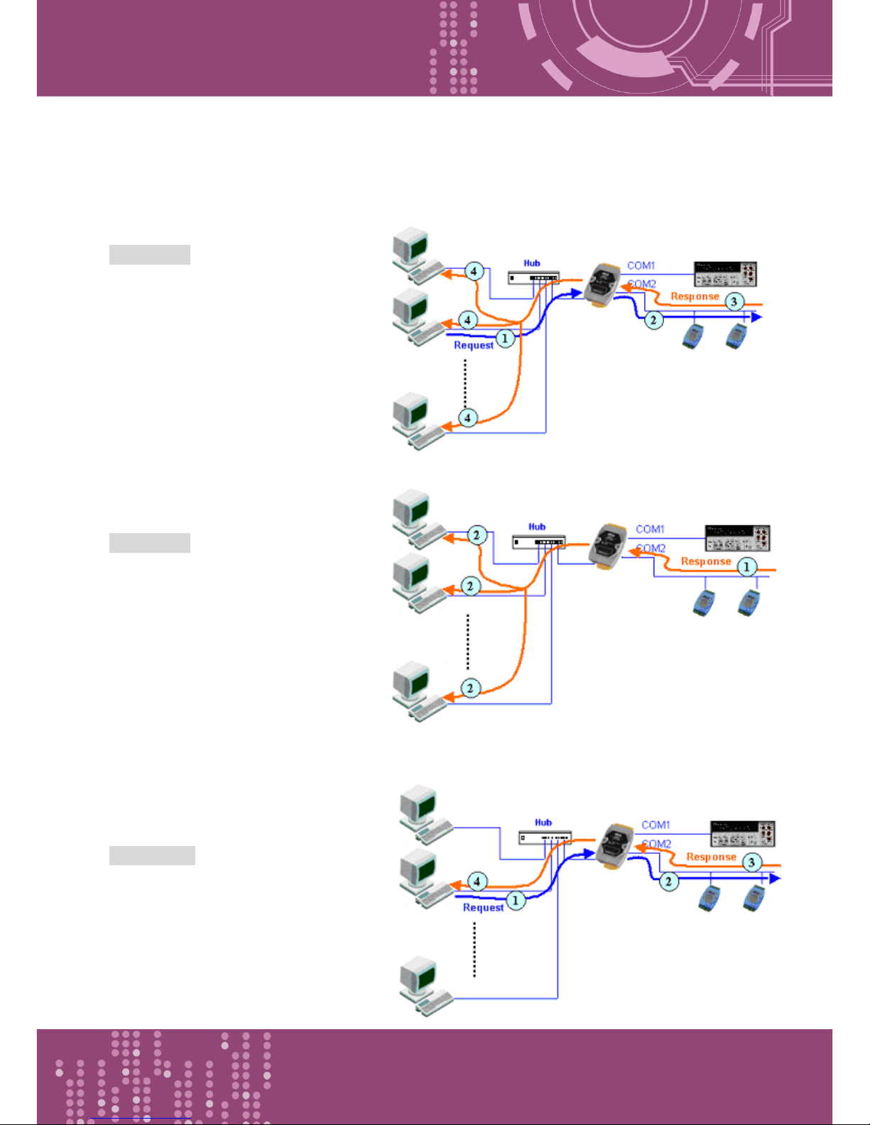
M0: Transparent Mode (Multi-echo mode)
Condition 1: One client sends a request
to the PDS-8x1 controller to access each
device. The PDS-8x1 controller echoes
the data from each device to each
connected client.
Condition 2: No clients send any
requests to the PDS-8x1 controller. The
PDS-8x1 controller echoes data from the
devices to each connected client.
M1: Slave Mode (Single-echo mode)
Condition 1: One client sends a request to
the PDS-8x1 controller to access the other
devices. The PDS-8x1 controller echoes
data from the devices to the client that
requested the service.
Page 50
Programmable Device Server with I/O Expansion Slot(s)
PDS-8x1 Series User Manual, Version 1.1.2, Apr. 2015 - 50 -
Condition 2: No clients send any requests
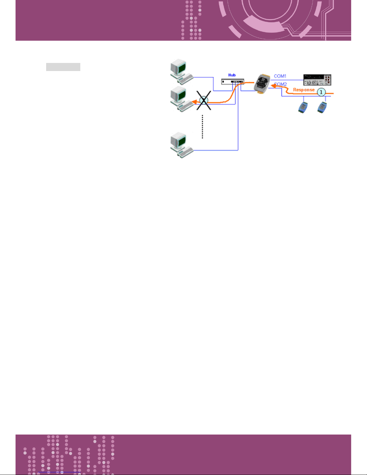
to the PDS-8x1 controller. The PDS-8x1
controller doesn’t echo any data from the
devices to any client.
M2: Half-Slave Mode (Is situated between M0 and the M1 mode)
If only one client connects to the PDS-8x1 controller, the operation mode same as M0 mode, please
refer to page 48 (M0: Transparent Mode); and if there are two or more clients connecting to the
PDS-8x1 controller, the operation mode same as M1 mode please refer to page 49 (M1: Slave
Mode).
Page 51
Programmable Device Server with I/O Expansion Slot(s)
PDS-8x1 Series User Manual, Version 1.1.2, Apr. 2015 - 51 -
4.3.2 Set Remote VCOM3 Connection
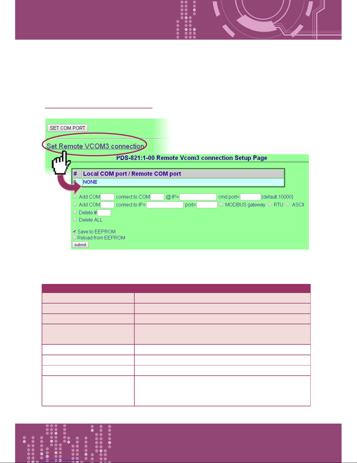
The “Set Remote VCOM3 Connection” section provides sets the pair-connection functions, the
more detailed information regarding pair-connection applications settings, please refer to the
Section 5.3 Pair-connection Applications.
The following is an overview of the parameters contained in the Remote Vcom3 connection Setup
Page section:
Item
Description
Add COM “Number”
Serial COM port number of the local device (Master)
connect to COM “Number”
Serial COM port number of the remote device (Slave)
@ IP= “IP Address”
IP address of the remote device (Slave)
cmd port= “command port”
(default: 10000)
Command Port number of the remote device (Slave)
Add COM “Number”
Serial COM port number of the local device (Master)
connect to IP= “IP Address”
IP address of the remote device (Slave)
Port= “TCP port”
TCP Port number of the remote device (Slave)
MODBUS gateway
If the “MODBUS gateway” checked, the serial port is specified
as gateway from the Modbus RTU or Modbus ASCII (Master)
to Modbus TCP for the remote device (Slave)
Page 52
Programmable Device Server with I/O Expansion Slot(s)
PDS-8x1 Series User Manual, Version 1.1.2, Apr. 2015 - 52 -
Item
Description
Delete # “Number”
Delete a specific # “Number” from the Pair-connection List.
Delete All
Delete all items from the pair-connection List.
Save to EEPROM
If the “submit” button is clicked with checking “Save to
EEPROM” option, the new settings will be saved to the PDS-8x1
controller only and the new settings will be valid after the next
power-on.
Reload from EEPROM
If the “submit” button is clicked with checking “Reload from
EEPROM” option, PDS-8x1 controller can apply the settings
from EEPROM immediately.
Submit
Click this button to save the revised settings to the PDS-8x1
controller.
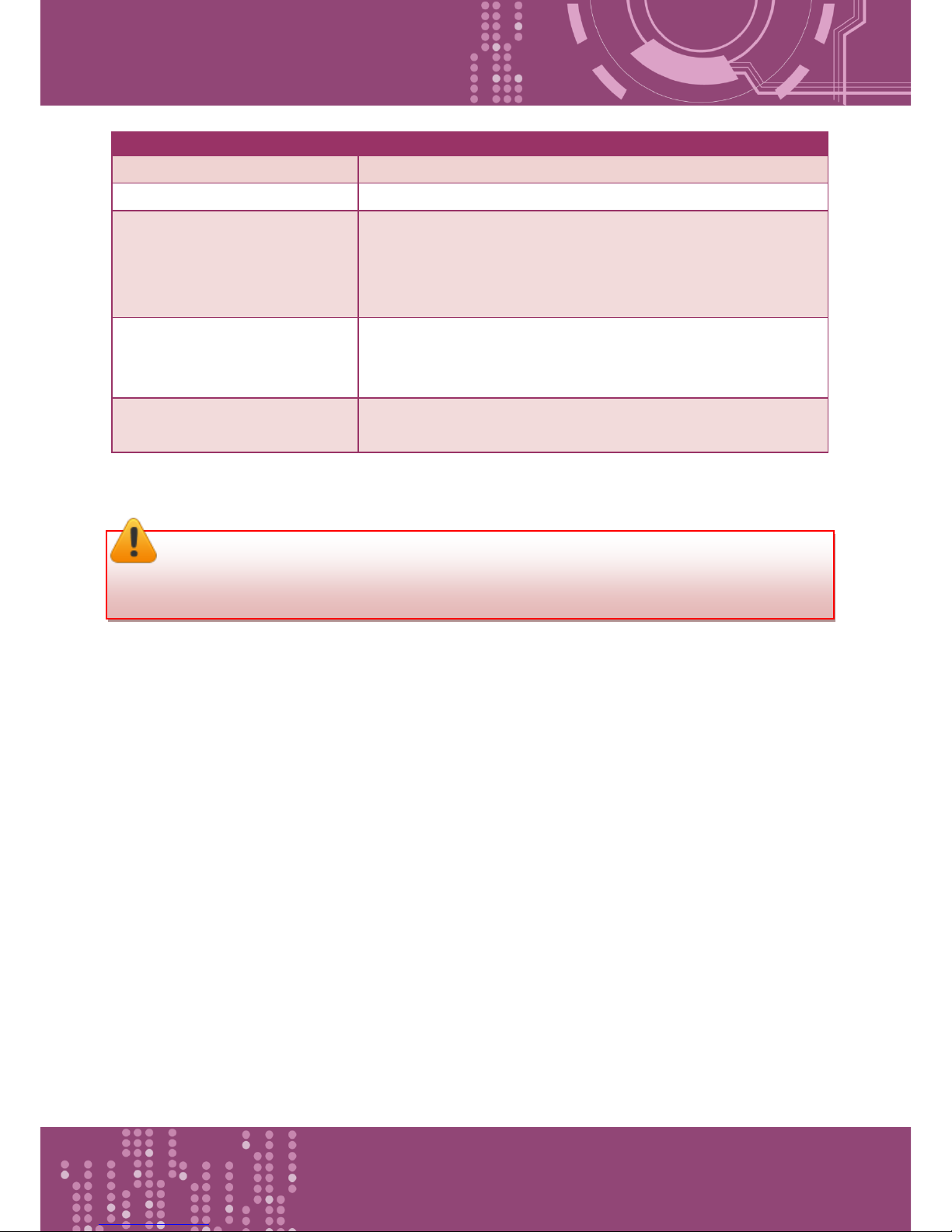
Note: After setting the pair-connection functions, please power-on reboot the PDS-8x1
controller, and then setting is complete.
Page 53
Programmable Device Server with I/O Expansion Slot(s)
PDS-8x1 Series User Manual, Version 1.1.2, Apr. 2015 - 53 -
4.4 Misc. Settings
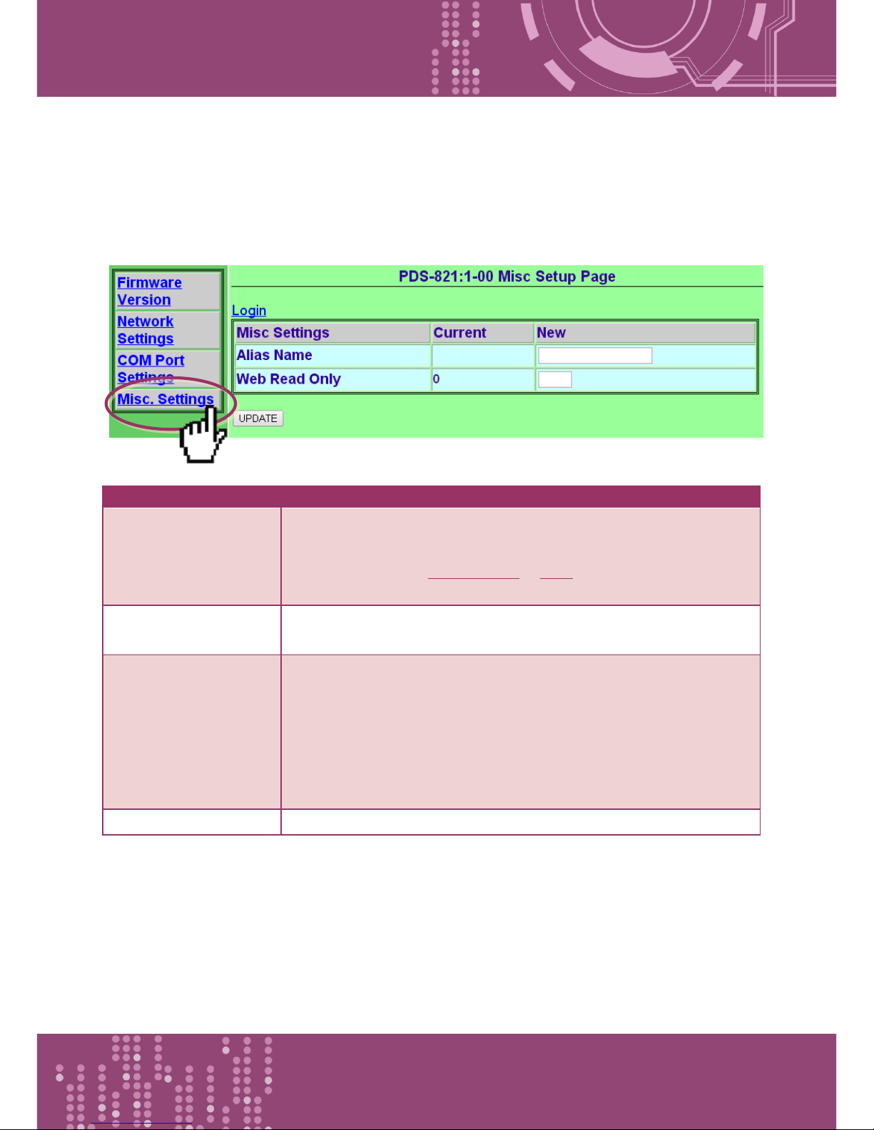
The Miscellaneous Settings provides functions allowing items such as the alias name, Web read
only, restore factory default and change password to be configured.
Item
Description
Login
Click the this tab to proceed to the Login page that can disable “Web
Read Only” property, change password and Restore to Factory Default
Settings, refer to the Sections 4.4.1 to 4.4.3 for more detail
information.
Alias Name
This parameter is used to assign an alias for each PDS-8x1 controller
to assist with easy identification.
Web Read Only
This parameter is used to enable “Web Read Only” function. If the
“Web Read Only” properly is set to 1 (Enabled), the web server will
not be able to save any new configurations to the PDS-8x1 controller.
The default setting should be 0 (Disabled).
0 = Disabled, 1 = Enabled
UPDATE
Click this button to save the revised settings to the PDS-8x1 controller.
Page 54
Programmable Device Server with I/O Expansion Slot(s)
PDS-8x1 Series User Manual, Version 1.1.2, Apr. 2015 - 54 -
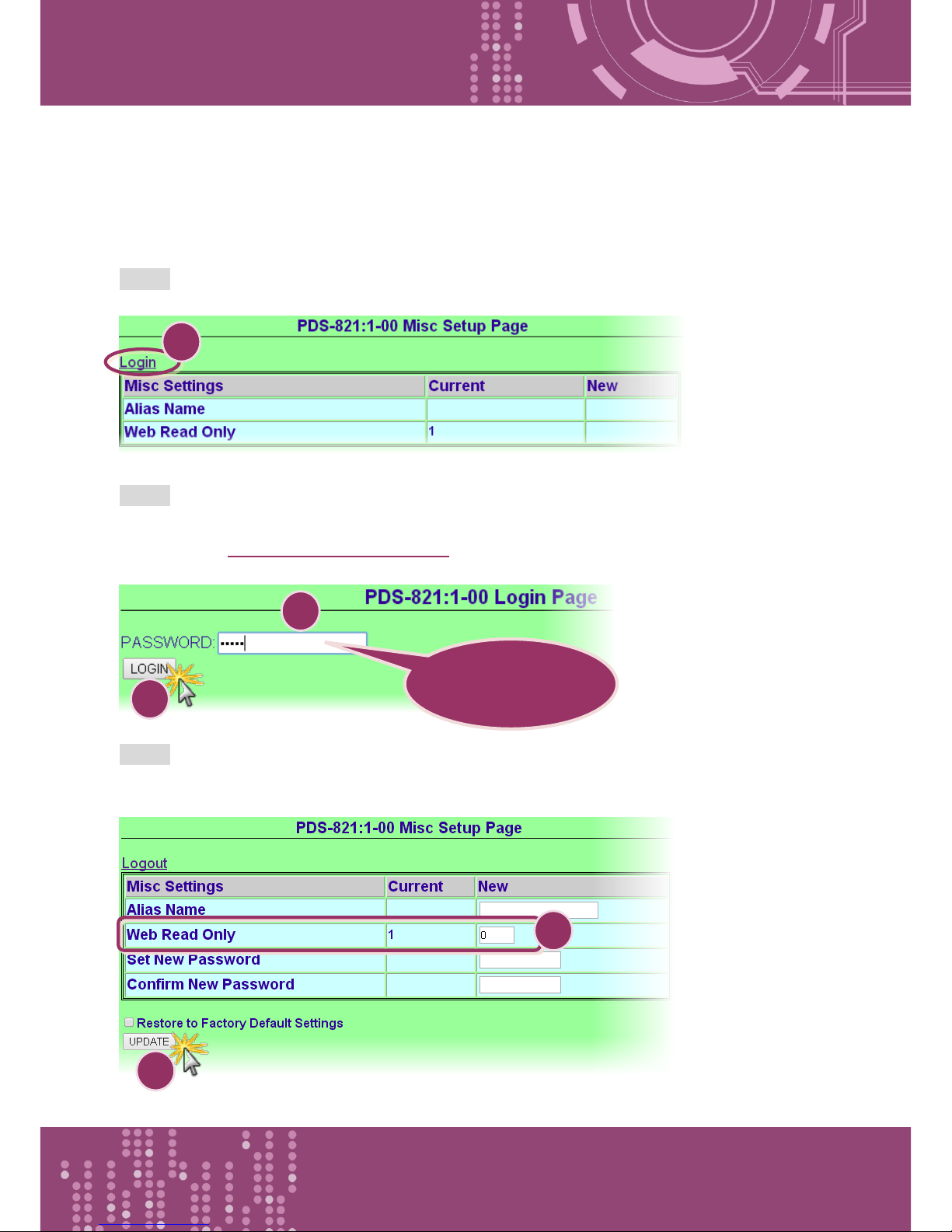
4.4.1 Disable the “Web Read Only” Function
The following instructions guide you to disable the “Web Read Only” function.
Step 1: Click the “Login” tab at the PDS-8x1 Misc Setup Page to proceed to the Login Page.
Step 2: Enter the password in the “PASSWORD:” field (use the default password “admin”) and click
the “LOGIN” button to proceed to the settings page. If you want to change default password,
please refer to Section 4.4.2 Change Password.
Step 3: Set the new “Web Read Only” properly = 0 and click the “UPDATE” button to update the
settings.
Default Password:
admin
1
2
3 4 5
Page 55
Programmable Device Server with I/O Expansion Slot(s)
PDS-8x1 Series User Manual, Version 1.1.2, Apr. 2015 - 55 -
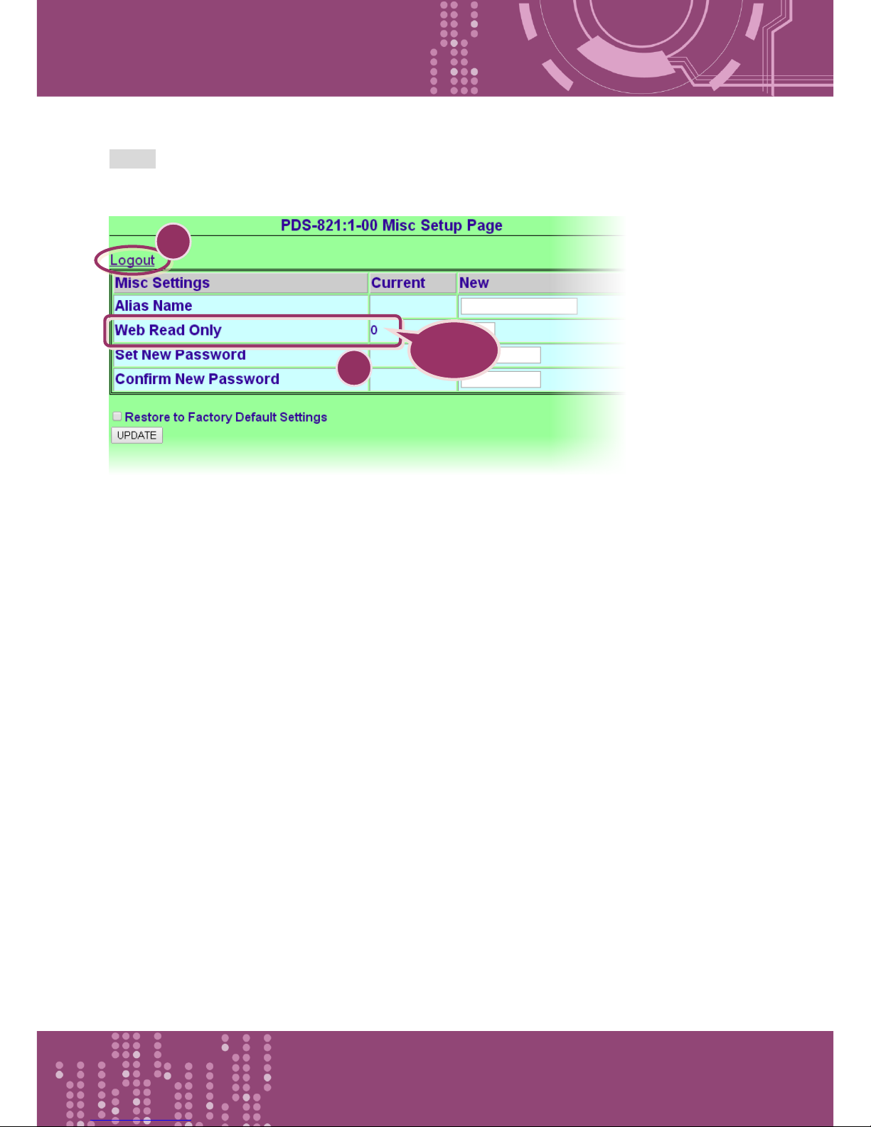
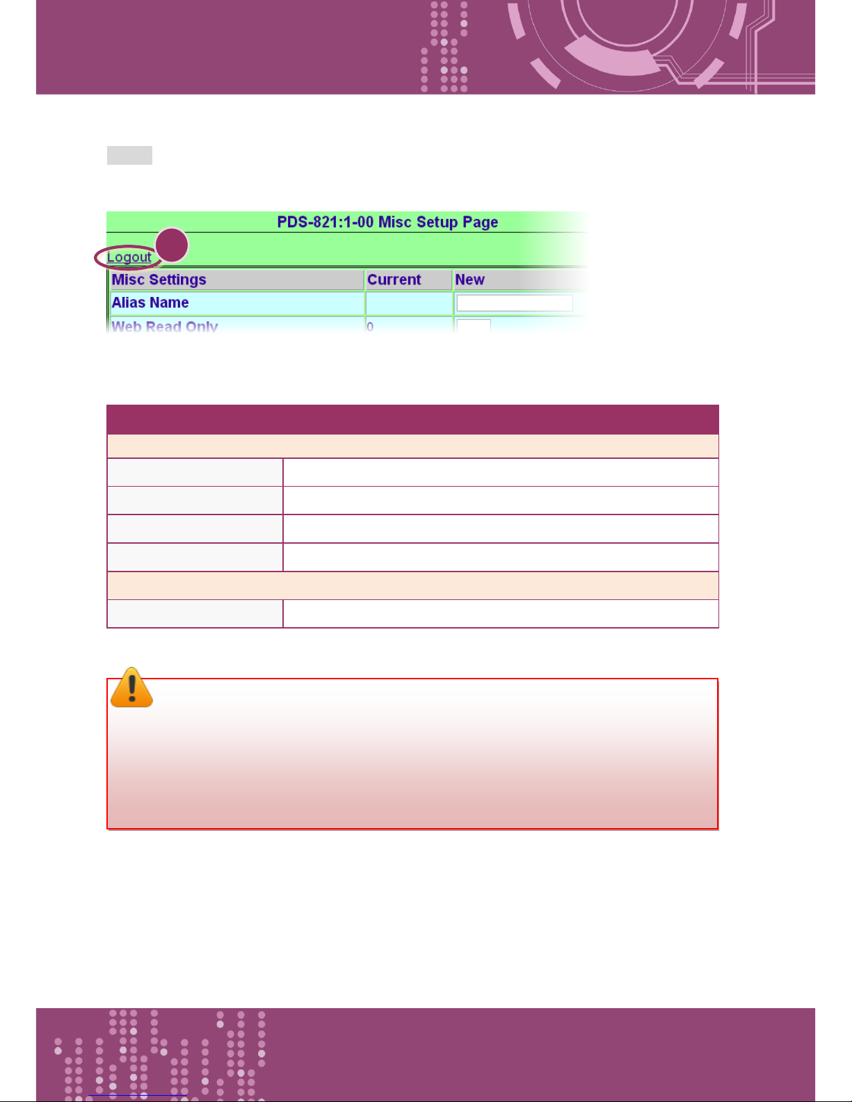
Step 4: Check that the current the “Web Read Only” = 0 and then click “Logout” to complete the
operation.
Check
6
7
Page 56
Programmable Device Server with I/O Expansion Slot(s)
PDS-8x1 Series User Manual, Version 1.1.2, Apr. 2015 - 56 -
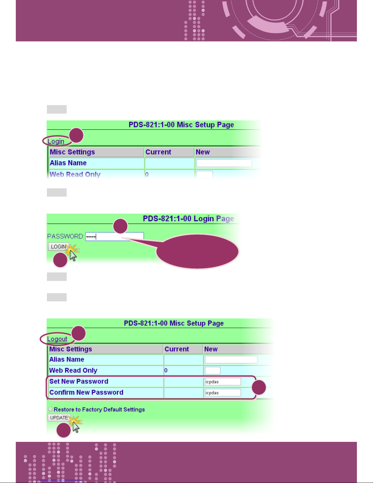
4.4.2 Change Password
To change a password of the Login Page, follow the procedure described below:
Step 1: Click the “Login” tab at the PDS-8x1 Misc Setup Page to proceed to the Login Page.
Step 2: Enter the password in the “PASSWORD:” field (use the default password “admin”) and click
the “LOGIN” button to proceed to the settings page.
Step 3: Enter the new password in the “Set New Password” field. Re-enter the new password in
the “Confirm new password” field.
Step 4: Click the “UPDATE” button to update the password, and then click the “Logout” to
complete the operation.
Default Password:
admin
1 2 3 4 5
6
Page 57
Programmable Device Server with I/O Expansion Slot(s)
PDS-8x1 Series User Manual, Version 1.1.2, Apr. 2015 - 57 -
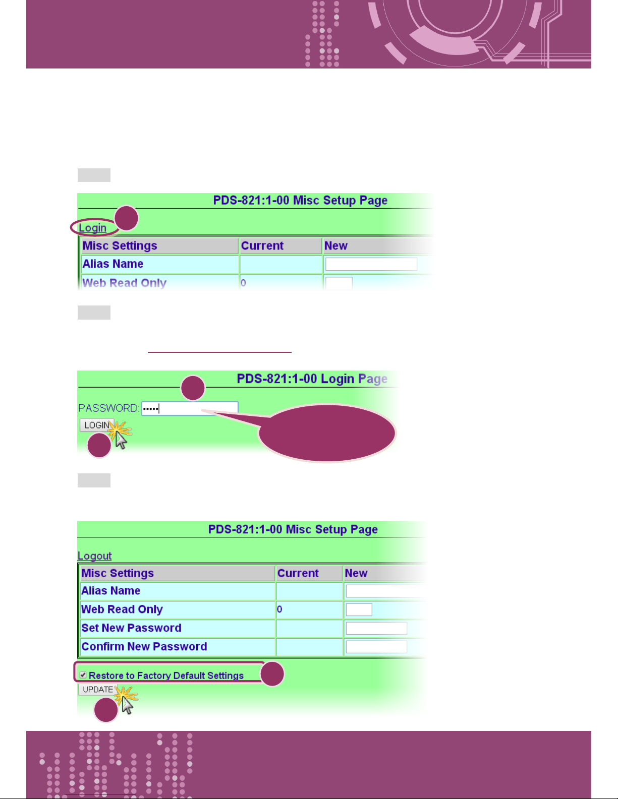
4.4.3 Restore to Factory Default Settings
Use the following procedure to reset all parameters to their original factory default settings:
Step 1: Click the “Login” tab at the PDS-8x1 Misc Setup Page to proceed to the Login Page.
Step 2: Enter the password in the “PASSWORD:” field (use the default password “admin”) and click
the “LOGIN” button to proceed to the settings page. If you want to change default password,
please refer to Section 4.4.2 Change Password.
Step 3: Check the “Restore to Factory Default Settings” option and click the “UPDATE” button to
update the setting.
Default Password:
admin
1
2
3 4 5
Page 58
Programmable Device Server with I/O Expansion Slot(s)
PDS-8x1 Series User Manual, Version 1.1.2, Apr. 2015 - 58 -
Step 4: Click the “Logout” to complete the operation, and then power-on reboot the PDS-8x1
controller.
The following is an overview of the factory default settings:
Factory Default Settings
Network Settings
IP Address
192.168.255.1
Gateway Address
192.168.0.1
Subnet Mask
255.255.0.0
DHCP
Disabled
Basic Settings
Alias
N/A
6
Note:
User can restore PDS-8x1 password to default value “admin” by using “config=RESET”
console command (refer to Chapter 6 Console/Telnet Commands List). This command sets
most configurations of PDS-8x1 to factory setting. It requires rebooting the PDS-8x1 for
loading new configuration (includes default password).
Page 59
Programmable Device Server with I/O Expansion Slot(s)
PDS-8x1 Series User Manual, Version 1.1.2, Apr. 2015 - 59 -
5. Typical Applications
5.1 Virtual COM Application
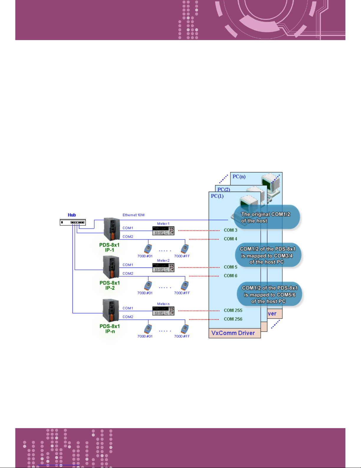
The PDS-8x1 controller is designed to link RS-232/422/485 devices to an Ethernet network. The
VxComm utility allows the built-in PDS-8x1 COM Port to be virtualized to a standard COM Port of a
host PC, as shown below:
In the configuration above, Meter-1 is virtualized to link to COM3 of the host PC. Therefore, a
program originally designed for the MS-COMM standard can access the meter without the need for
any modification.
Page 60
Programmable Device Server with I/O Expansion Slot(s)
PDS-8x1 Series User Manual, Version 1.1.2, Apr. 2015 - 60 -
5.2 Ethernet I/O Applications
Linking to I-7000 series modules
The I-7000 series provides a variety of I/O operations, such as D/I, D/O, A/D, D/A, Counter and
Frequency Measurement, etc. The I-7000 series was originally designed to be used with RS-485
networks, so the RS-485 of COM on the PDS-8x1 can be used to link to I-7000 series modules.
By using VxComm technology, programs that support serial devices on the host PC can be upgraded
from an RS-485 network to an Ethernet network without requiring any modifications to the
program.
Configurable Ethernet Data Logger
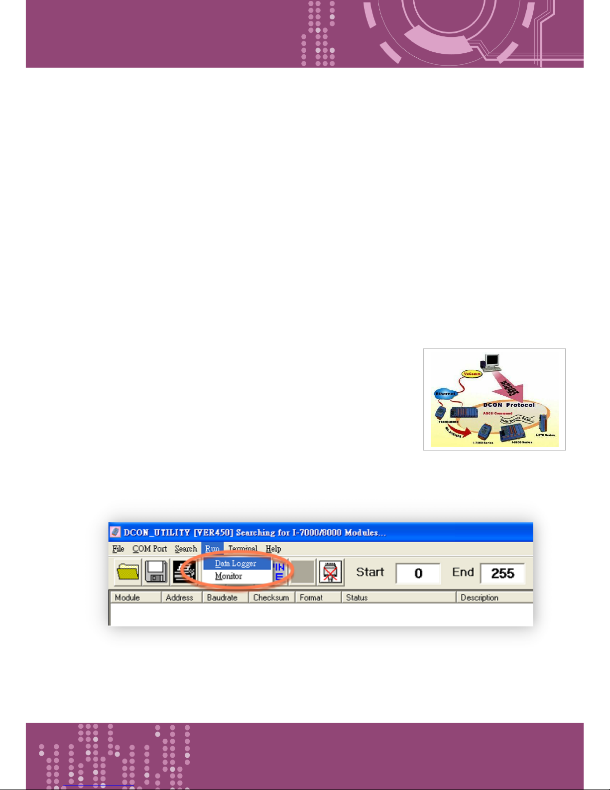
Using the VxComm driver, the PDS-8x1 + 7000 modules can be virtualized
to become COM Port + 7000 modules located on the host PC, and then
the Data Logger in the DCON Utility can be used to access data related to
the I-7000 from the Ethernet. Signal data originating from the I-7000
modules can be analyzed using MS Excel without the need to write any
custom programs.
1: The DCON utility includes a log function, as show below:
Page 61
Programmable Device Server with I/O Expansion Slot(s)
PDS-8x1 Series User Manual, Version 1.1.2, Apr. 2015 - 61 -
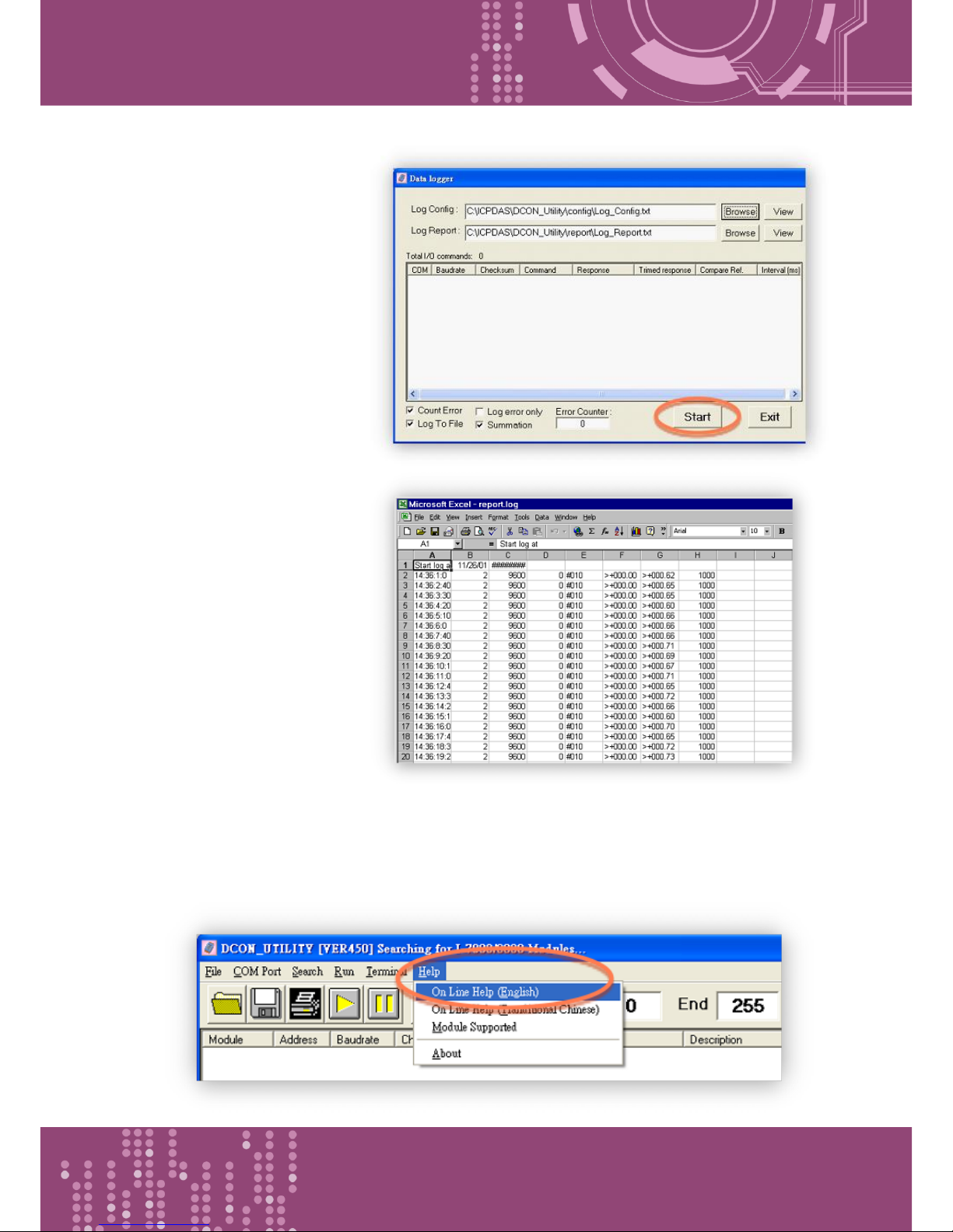
2: Configure the system
connection as shown below
and click the “Start” button
to begin logging data.
3: Open the log file in MS Excel
to view the log data as shown
in the example below:
By using the I-7000 DCON utility and MS Excel in conjunction with VxComm technology, the signal
data originating from I-7000 modules via the Ethernet network can be analyzed without the need
to write custom programs. For more information about the log function, refer to the online help
feature (English and Traditional Chinese) of the DCON utility.
Page 62
Programmable Device Server with I/O Expansion Slot(s)
PDS-8x1 Series User Manual, Version 1.1.2, Apr. 2015 - 62 -
5.3 Pair-connection Applications
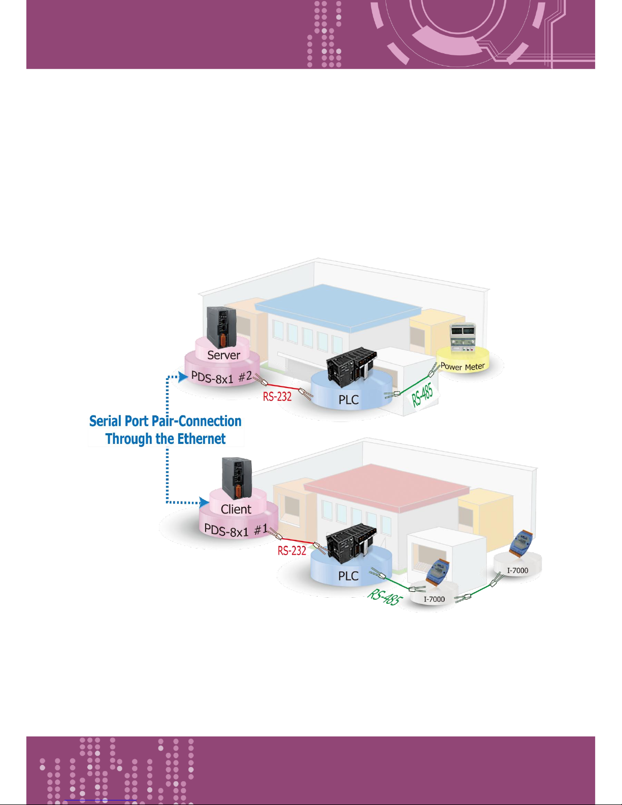
PDS-8x1 controller can be used to create a pair-connection application (as well as serial-bridge or
serial-tunnel), and then route data between two serial devices via TCP/IP, which is useful when
connecting mainframe computers, servers or other serial devices that do not themselves have
Ethernet capability.
Page 63
Programmable Device Server with I/O Expansion Slot(s)
PDS-8x1 Series User Manual, Version 1.1.2, Apr. 2015 - 63 -
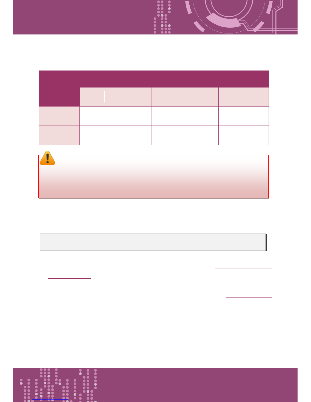
The following are examples of pair-connection tests:
Pair-connection Settings:
Model
Port Settings
(default)
Pair-connection Settings
COM
Port
Baud
Rate
Data
Format
Remote
Server IP
Remote TCP Port
(default)
PDS-8x1 #1
(Client Mode)
COM1
9600
8N1
IP Address of PDS-8x1 #2
10001
PDS-8x1 #2
(Server Mode)
COM1
9600
8N1 - -
Follow the procedure described below:
Step 1: Connecting to a network, PC and Power
1. Confirm that the PDS-8x1 controllers are functioning correctly. Refer to Chapter 3 Setting up the
PDS-8x1 controller for more details.
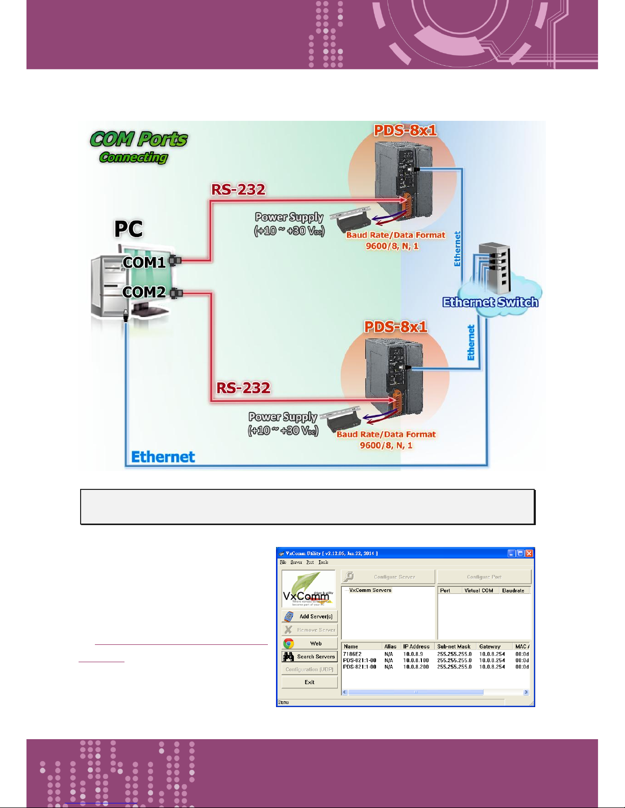
2. Connect COM1 of the PC to COM1 of the PDS-8x1 #1, and then connect COM2 of the PC to
COM1 of the PDS-8x1 #2. For detailed RS-232 wiring information, refer to Section 2.7 “Wiring
Notes for RS-232/485/422 Interfaces”.
3. Supply +24 V
DC
(+10 ~ +30 VDC) power to the PDS-8x1 controller.
※ Refer to Figure 5-3.1 for an illustration of how to perform the above steps.
Note:
The Baud Rate and Data Format settings of the client and server (PDS-8x1 #1 and #2) depend
on the COM ports of the PC (or the connected device).
Page 64
Programmable Device Server with I/O Expansion Slot(s)
PDS-8x1 Series User Manual, Version 1.1.2, Apr. 2015 - 64 -
The image below shows an example of the setup for a pair-connection test:
Step 2: Configuring the Ethernet Settings
Contact your Network Administrator to
obtain the correct and functioning
network configuration for the PDS-8x1
controllers (including the IP Address,
Mask and Gateway details). Also refer
to Chapter 3 Setting up the PDS-8x1
controller for more details.
Figure 5-3.1
Figure 5-3.2
Page 65
Programmable Device Server with I/O Expansion Slot(s)
PDS-8x1 Series User Manual, Version 1.1.2, Apr. 2015 - 65 -
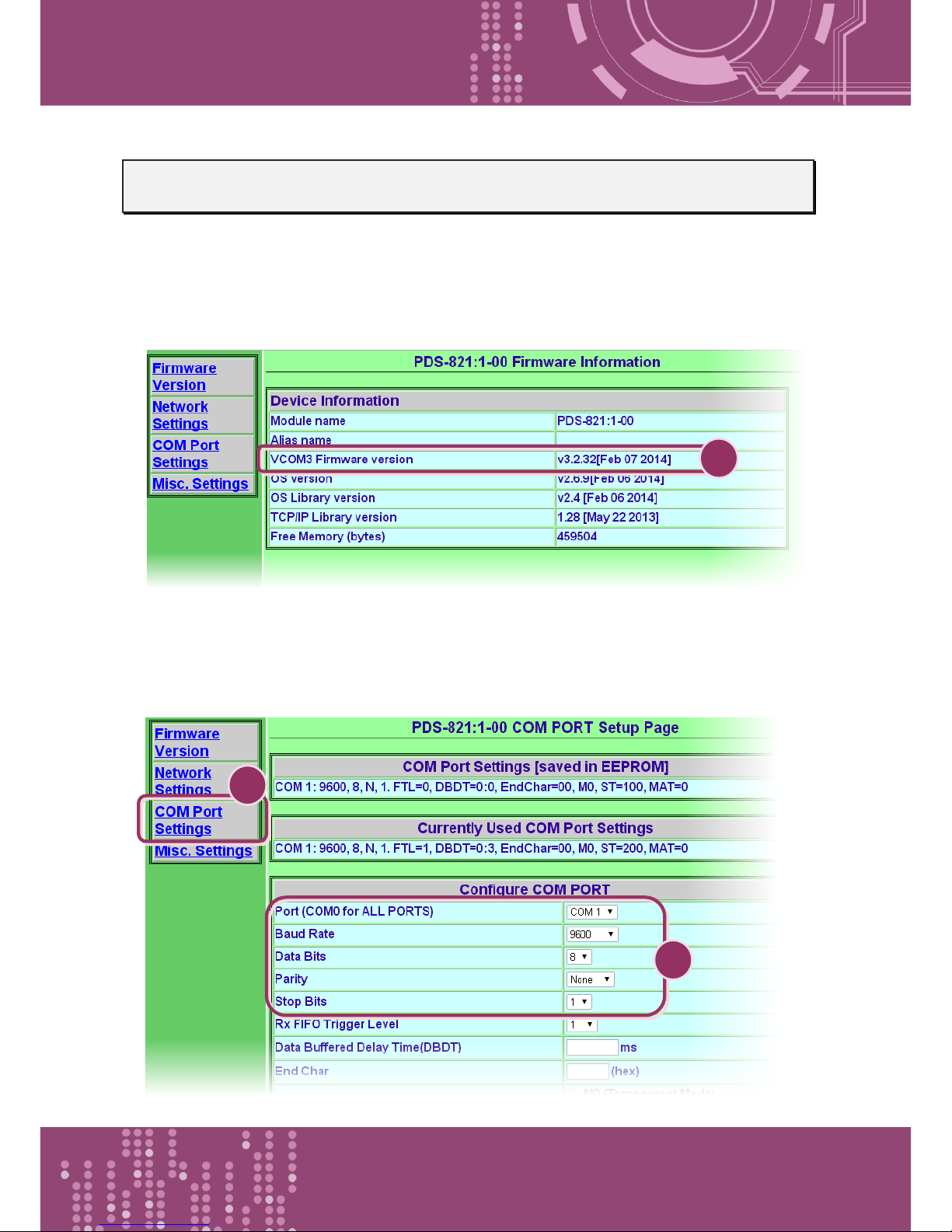
Step 3: Configuring the Pair-connection (Client Mode) on the Web Server for PDS-8x1 #1
1. Enter the URL address of the PDS-8x1 #1 in the address bar of the browser or click the “Web”
button in the VxComm Utility to log in to the web configuration page.
2. Check firmware version is v3.2.32[Feb 07 2014] or later of the PDS-8x1 #1.
3. Click the “COM Port Settings” tag to enter the settings page, and select the appropriate COM
Port number, Baud Rate and Data Format settings from the relevant drop down options, for
example “9600”, “8”, “None” and 1” .
1 3 2
Figure 5-3.3
Figure 5-3.4
Page 66
Programmable Device Server with I/O Expansion Slot(s)
PDS-8x1 Series User Manual, Version 1.1.2, Apr. 2015 - 66 -
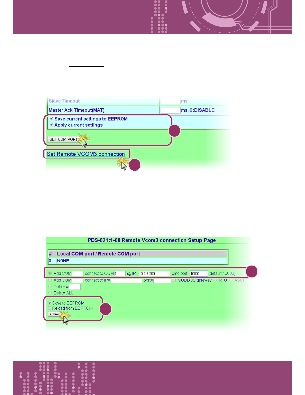
4. Check the “Save current settings to EEPROM” and “Apply Current settings” options, and then
click the “SET COM PORT” button to finish configuration.
5. Click “Set Remote VCOM3 connection” to proceed to the PDS-8x1 Remote Vcom3 connection
Setup Page (Pair-connection settings).
6. Select “Add COM” and type in the COM port of the PDS-8x1 #1 (Client) which you want to use.
Type the appropriate COM Port number, IP address and command port of the PDS-8x1 #2
(Server) settings in the relevant fields, for example “COM: 1”, “IP: 10.0.8.200” and “cmd port:
10000”.
7. Check the “Save to EEPROM” option and click “submit” button to update configuration.
4
5
7
Figure 5-3.5
Figure 5-3.6
6
Page 67
Programmable Device Server with I/O Expansion Slot(s)
PDS-8x1 Series User Manual, Version 1.1.2, Apr. 2015 - 67 -
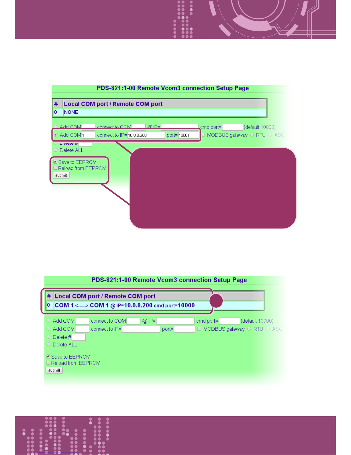
※ If the remote device isn’t our product and doesn’t support command port 10000, refer to the
following to configure pair-connection function.
8. Check the Local COM Port/Remote COM port area for pair-connection setting.
9. Reboot PDS-8x1 #1(Client) and then setting is complete.
8
6. Select “Add COM” and type in the COM port of the
PDS-8x1 #1 (Client) which you want to use. Type the
appropriate IP address and TCP Port of the PDS-8x1
#2 (Server) settings in the relevant fields, for example
“IP: 10.0.8.200” and “port: 10001”.
7. Check the “Save to EEPROM” option and click
“submit” button to update configuration.
Figure 5-3.7
Figure 5-3.8
Page 68
Programmable Device Server with I/O Expansion Slot(s)
PDS-8x1 Series User Manual, Version 1.1.2, Apr. 2015 - 68 -
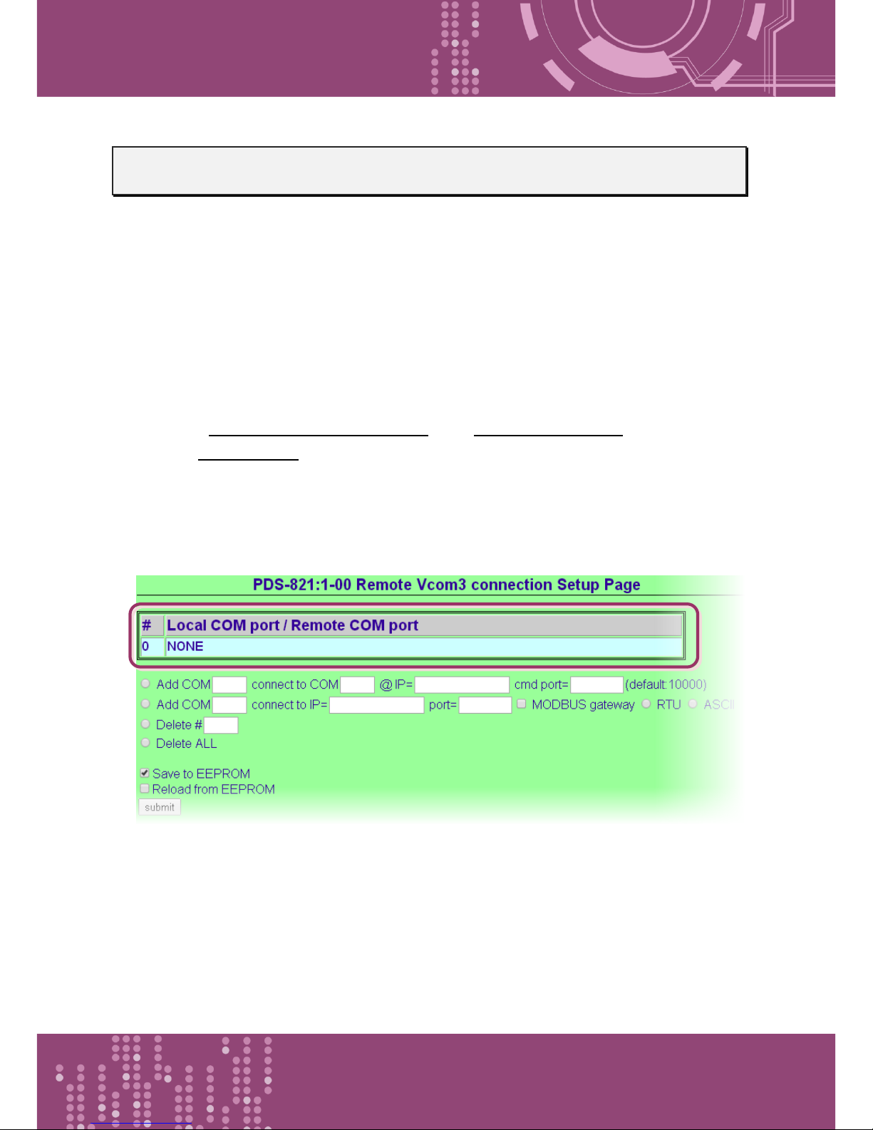
Step 4: Configuring the Pair-connection (Server Mode) on the Web Server for PDS-8x1 #2
1. Enter the URL address of the PDS-8x1 #2 in the address bar of the browser or click the “Web”
button in the VxComm Utility to log in to the web configuration page.
2. Click the “COM Port Settings” tag to enter the settings page, and select the appropriate COM
Port number, Baud Rate and Data Format settings from the relevant drop down options, for
example “9600”, “8”, “None” and 1” .
(Refer to Figure 5-3.4 for illustrations of how to perform the above step 2.)
3. Check the “Save current settings to EEPROM” and “Apply Current settings” items, and then
click the “SET COM PORT” button to finish configuration.
4. Click “Set Remote VCOM3 connection” at the PDS-8x1 #2 (Server) COM PORT setup page.
(Refer to Figure 5-3.5 for illustrations of how to perform the steps 3 and 4.)
5. Confirm that the Local COM port/Remote COM port area of the PDS-8x1#2 (Server) is “None”.
Figure 5-3.9
Page 69
Programmable Device Server with I/O Expansion Slot(s)
PDS-8x1 Series User Manual, Version 1.1.2, Apr. 2015 - 69 -
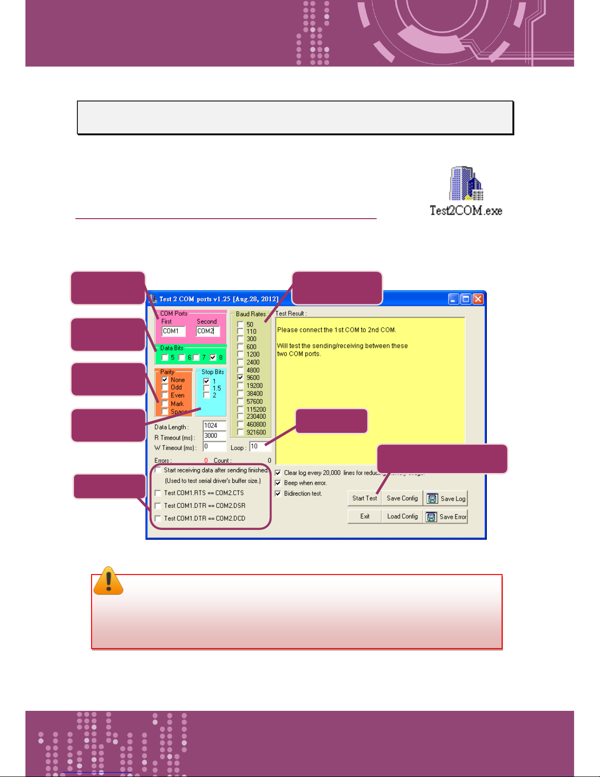
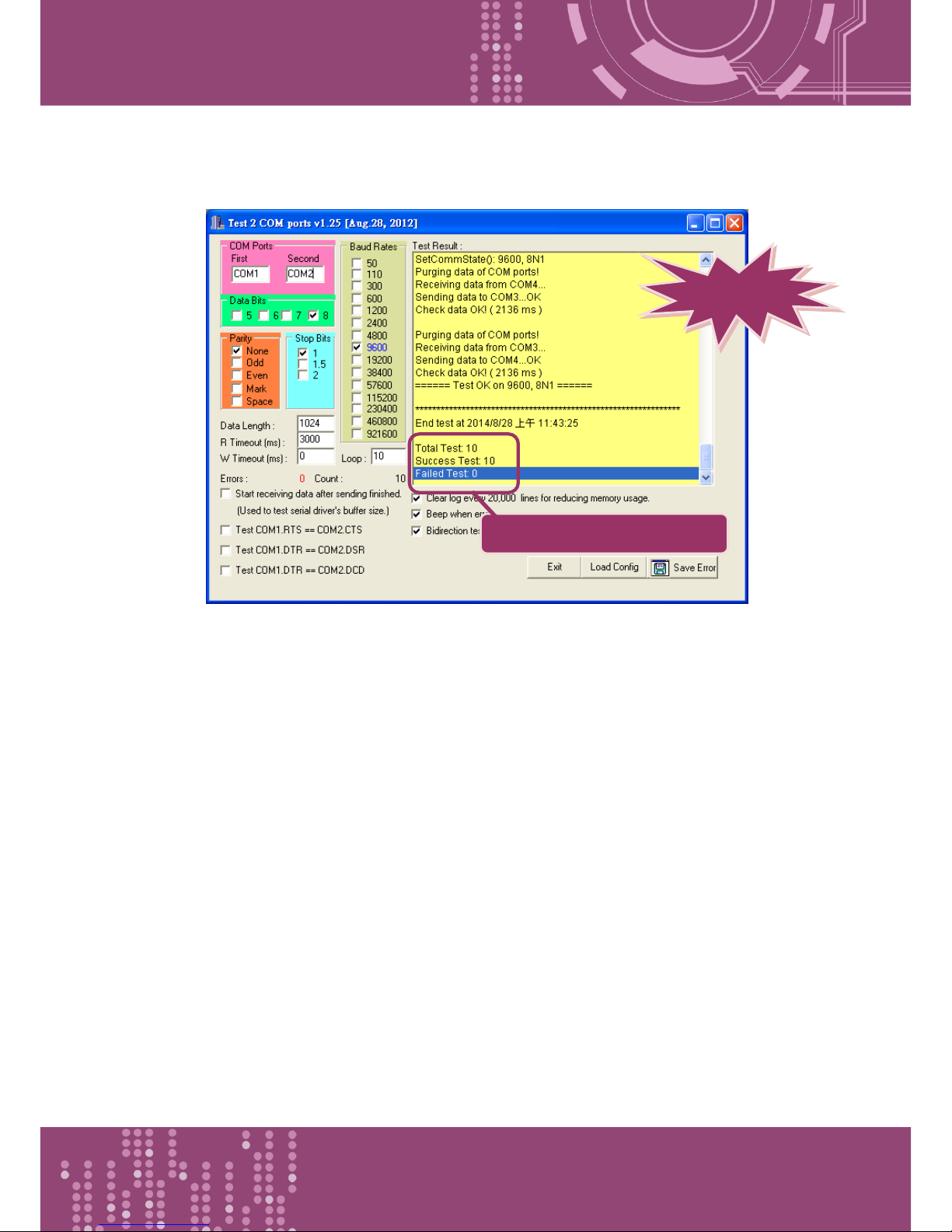
Step 5: Testing the Pair-connection Functions
1. The Test2COM.exe program is located at:
CD:\Napdos\multiport\utility
http://ftp.icpdas.com/pub/cd/iocard/pci/napdos/multiport/utility/
2. Execute the Test2COM.exe program.
2. Check
Data Bits: 8
1. Type
COM1\COM2
3. Check
Parity: None
4. Check
Stop bits: 1
5. Check
Baud Rates: 9600
6. Uncheck
7. Loop: 10
8. Click “Start Test” button
Note:
The Baud Rate and data format depend on the serial port settings for the web
configuration of the PDS-8x1 #1 and PDS-8x1 #2.
Page 70
Programmable Device Server with I/O Expansion Slot(s)
PDS-8x1 Series User Manual, Version 1.1.2, Apr. 2015 - 70 -
3. Get the test result.
9. Test Results: “Failed Test: 0 ”
Complete
Page 71
Programmable Device Server with I/O Expansion Slot(s)
PDS-8x1 Series User Manual, Version 1.1.2, Apr. 2015 - 71 -
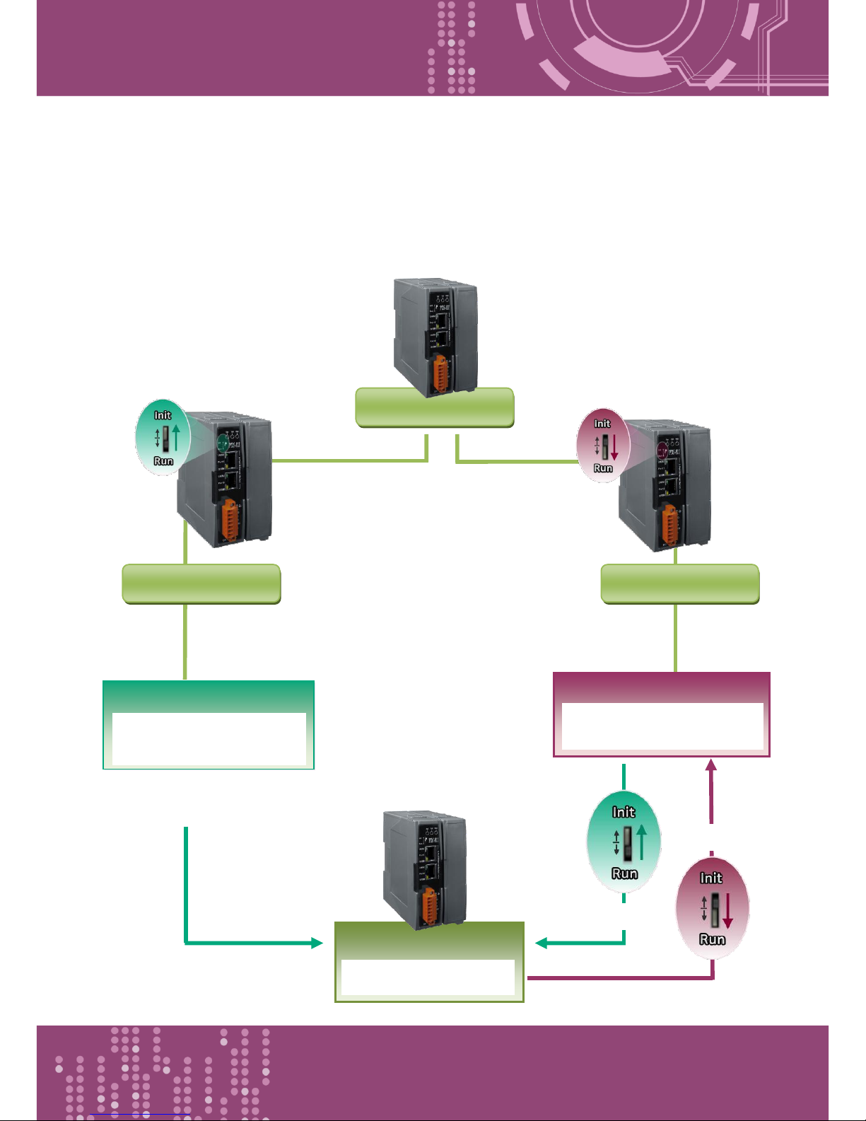
Init
6. Console/Telnet Commands List
6.1 Operation Flowchart
PDS-8x1 Power OFF
Run
PDS-8x1 Power ON
PDS-8x1 Power ON
Init Mode
*for MiniOS7 Commands
*for Downloading Firmware
Run Firmware
(vp8_3230/autoexec)
Console Mode
*for Console Commands
Run Mode
*for Virtual COM applications
Init
Run
Page 72

Programmable Device Server with I/O Expansion Slot(s)
PDS-8x1 Series User Manual, Version 1.1.2, Apr. 2015 - 72 -
6.2 Comparison Sheet (Init, Run and Console Modes)
Mode
Firmware
VCOM Commands
Telnet Commands
Console Commands
Init
Stop
No
No
No
Init Mode is used to upgrade firmware and accepts MiniOS7 commands (from
PDS.COM1) only.
Run
Running
Yes
Yes
No
Run Mode is used for Virtual COM applications, and accepts Virtual COM commands
(TCP port 10000) and Telnet commands (TCP port 23).
Console
Running
Yes
Yes
Yes
Console Mode is used to configure the Virtual COM.
PDS.COM1 is the console port that accepts console commands while other ports are
still working with Virtual COM applications.
Page 73
Programmable Device Server with I/O Expansion Slot(s)
PDS-8x1 Series User Manual, Version 1.1.2, Apr. 2015 - 73 -
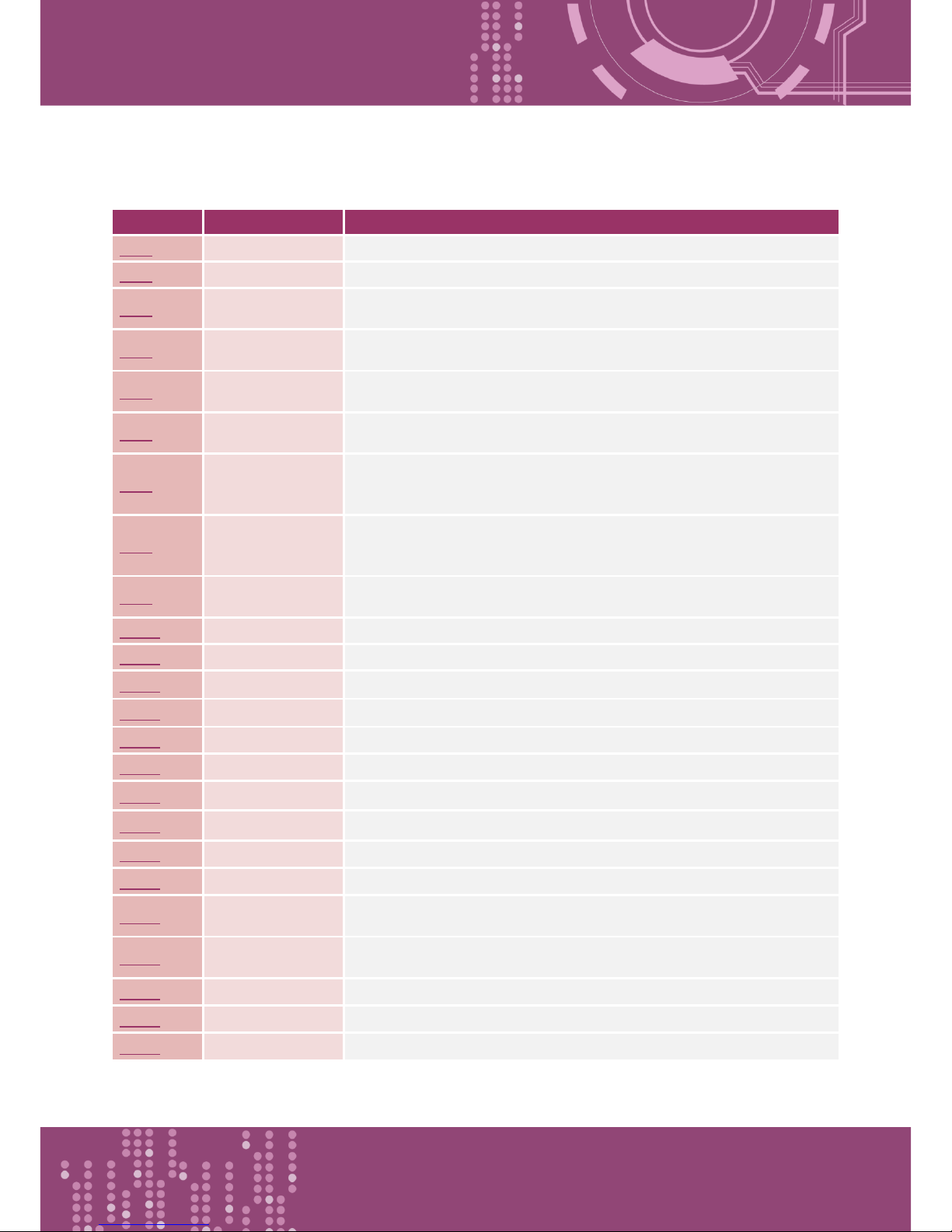
6.3 Command List
Section
Command
Description
6.3.1
IPFILTER
Retrieves/Sets the IP addresses that are allowed to access the PDS-8x1.
6.3.2
IPCONF
Queries the network configuration. (IP/Mask/Gateway/MAC addresses).
6.3.3
SOCKET
Lists all the status of sockets (Listen/Not Used Yet) together with the
type of each socket (TCP Server: Port No./UDP/Unused).
6.3.4
COM
Queries or sets the configuration of the COM Ports (Baud Rate/Parity
/Stop Bits)
6.3.5
Broadcast
Queries or sets the Broadcast parameter, which determines whether or
not the module can receive Broadcast packets.
6.3.6
SystemTimeout
If PDS-8x1 has no network communications during the SystemTimeout
period, the PDS-8x1 will reboot it-self automatically.
6.3.7
SocketTimeout
If there is no data send/receive on the connection during the
SocketTimeout period, the PDS-8x1 will close the connection
automatically.
6.3.8
M
Gets/Sets the echo mode.
/M0: Transparent Mode, Multi-Echo, Data-Shared.
/M1: Slave Mode, Single-Echo, None-Shared.
6.3.9
EchoCmdNo
Queries or sets the EchoCmdNo parameter that enables or disables
adding Command Number before response.
6.3.10
EndChar
Sets a character that determines the end of a response string.
6.3.11
IP
Queries or sets the IP address.
6.3.12
MASK
Queries or sets the subnet Mask value.
6.3.13
GATEWAY
Queries or sets the Gateway address.
6.3.14
MAC
Queries the MAC address.
6.3.15
NAME
Queries the module name.
6.3.16
ALIAS
Sets the alias for a PDS-8x1.
6.3.17
DHCP
Enables/Disables the DHCP client.
6.3.18
UDP
Sets whether to reply to a UDP search command.
6.3.19
VER
Queries the version information
6.3.20
SAVE
Determines whether or not backup copies of the "autoexec.bat" and
"vcom.ini" files are saved when using the “load” command.
6.3.21
LOAD
Loads file to the built-in flash disk on PDS-8x1. It should be used to
update firmware only.
6.3.22
CONFIG
Restores the factory default settings.
6.3.23
RESET
Reboots the PDS-8x1 module.
6.3.24
QUIT
Exits the running firmware.
Page 74

Programmable Device Server with I/O Expansion Slot(s)
PDS-8x1 Series User Manual, Version 1.1.2, Apr. 2015 - 74 -
6.3.1 IPFILTER
This command is used to query or edit IP filter table. The IP filter table restricts the access of
packets based on the IP header. If one or more IP addresses are saved into the IP filter table, only
clients whose IP is specified in the IP filter table can access the PDS-8x1.
Effect: Immediate
Command
Arguments
Description
ipfilter
Queries the IP filter table.
ipfilter
ADD ip1
ADD ip1 ip2
Adds an IP address to the IP filter table.
Adds a range of IP addresses (ip1 ~ ip2) to the IP filter table.
ipfilter
DEL ip1
DEL ip1 ip2
Deletes an IP address (ip1) from the IP filter table.
Deletes a range of IP addresses (ip1 ~ ip2) from the IP filter
table.
The IP address that follows the DEL command should already be
listed in the IP filter table.
ipfilter
DEL #n
Deletes item “n” from the IP filter table.
ipfilter
DEL @
Deletes all items from the IP filter table.
ipfilter
SAVE
Saves the IP filter table to the EEPROM. If the IP filter table is
empty, the data in EEPROM will be cleared.
ipfilter
LOAD
Loads the IP filter table from the EEPROM.
※The IP filter table is loaded automatically when the PDS-8x1 is booted.
※Use the “ipfilter save” command to save a new IP filter table to the EEPROM.
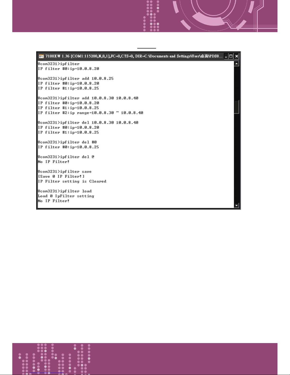
Refer to Figure 6-3.1 for detail illustrations.
Page 75
Programmable Device Server with I/O Expansion Slot(s)
PDS-8x1 Series User Manual, Version 1.1.2, Apr. 2015 - 75 -
Figure 6-3.1: The following is an example of a IPFILTER configuration.
Page 76
Programmable Device Server with I/O Expansion Slot(s)
PDS-8x1 Series User Manual, Version 1.1.2, Apr. 2015 - 76 -
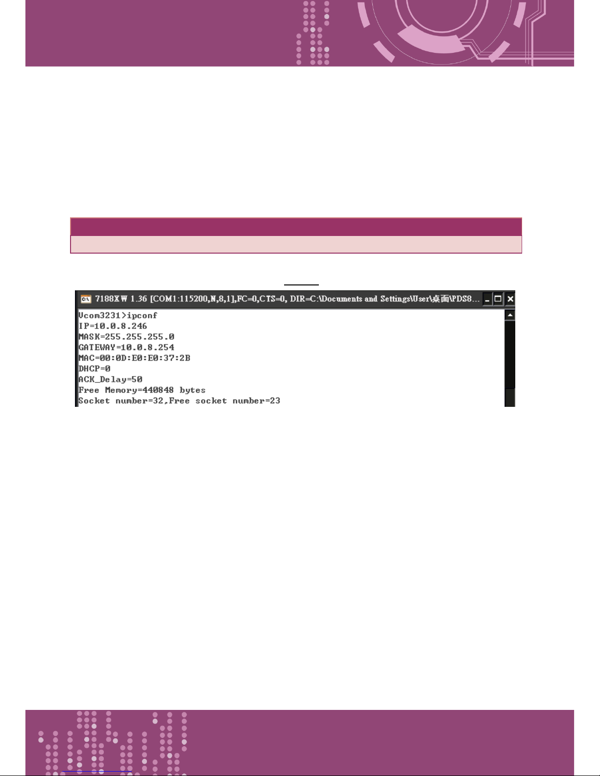
6.3.2 IPCONF
This command is used to display the network configuration information, such as IP address, Mask
Address, Gateway address and MAC address and the status of DHCP, ACK_Delay, Free Memory and
Socket status.
Effect: Immediate
Command
Arguments
Description
ipconf
Queries the network configuration.
Figure 6-3.2: The following is an example of a IPCONF configuration.
Page 77
Programmable Device Server with I/O Expansion Slot(s)
PDS-8x1 Series User Manual, Version 1.1.2, Apr. 2015 - 77 -
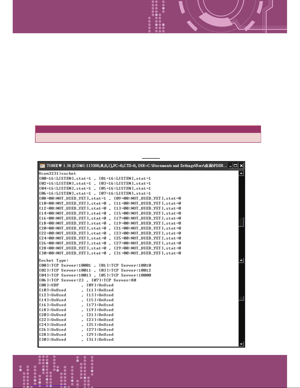
6.3.3 SOCKET
This command lists the status of all sockets (Listen/Not Used Yet) together with the type of each
socket (TCP Server: Port No./UDP/Unused)
If stat = 1, the socket is used.
If stat = 0, the socket is not yet used.
Effect: Immediate
Command
Arguments
Description
socket
Lists the status of all sockets.
Figure 6-3.3: The following is an example of a SOCKET configuration.
Page 78
Programmable Device Server with I/O Expansion Slot(s)
PDS-8x1 Series User Manual, Version 1.1.2, Apr. 2015 - 78 -
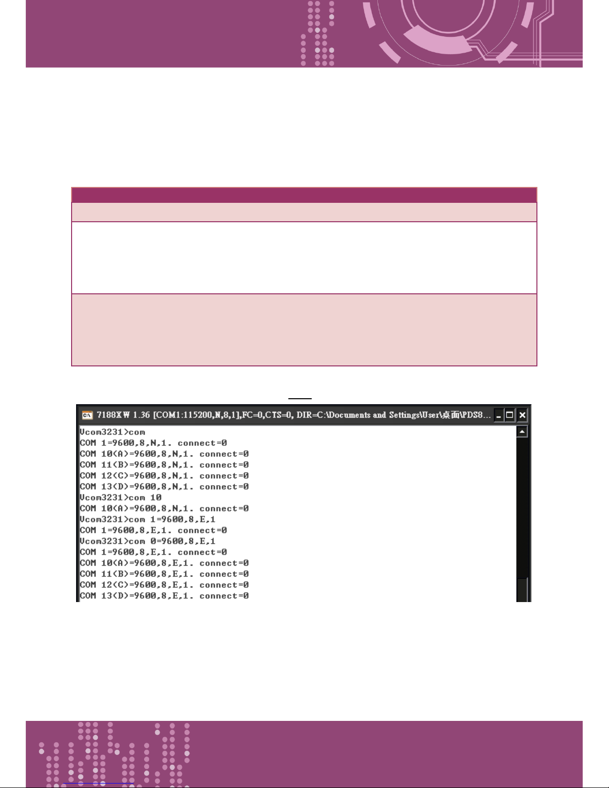
6.3.4 COM
This command queries or sets the configuration of the COM Ports (Baud Rate/Parity/Stop bits).
Effect: Immediate
Command
Arguments
Description
com
Queries the configuration of all COM Ports.
com
n
Queries configuration of COM Port “n”.
If n = 0, the configuration of all COM Ports will be listed in the
same way as using the command “com” above.
com
N= BaudRate,
DataBits,
Parity,StopBit(s)
Sets the configuration of COM Port “n”.
If n = 0, the settings will be valid for all Com Ports on the PDS-
8x1.
Figure 6-3.4: The following is an example of a COM configuration.
Page 79
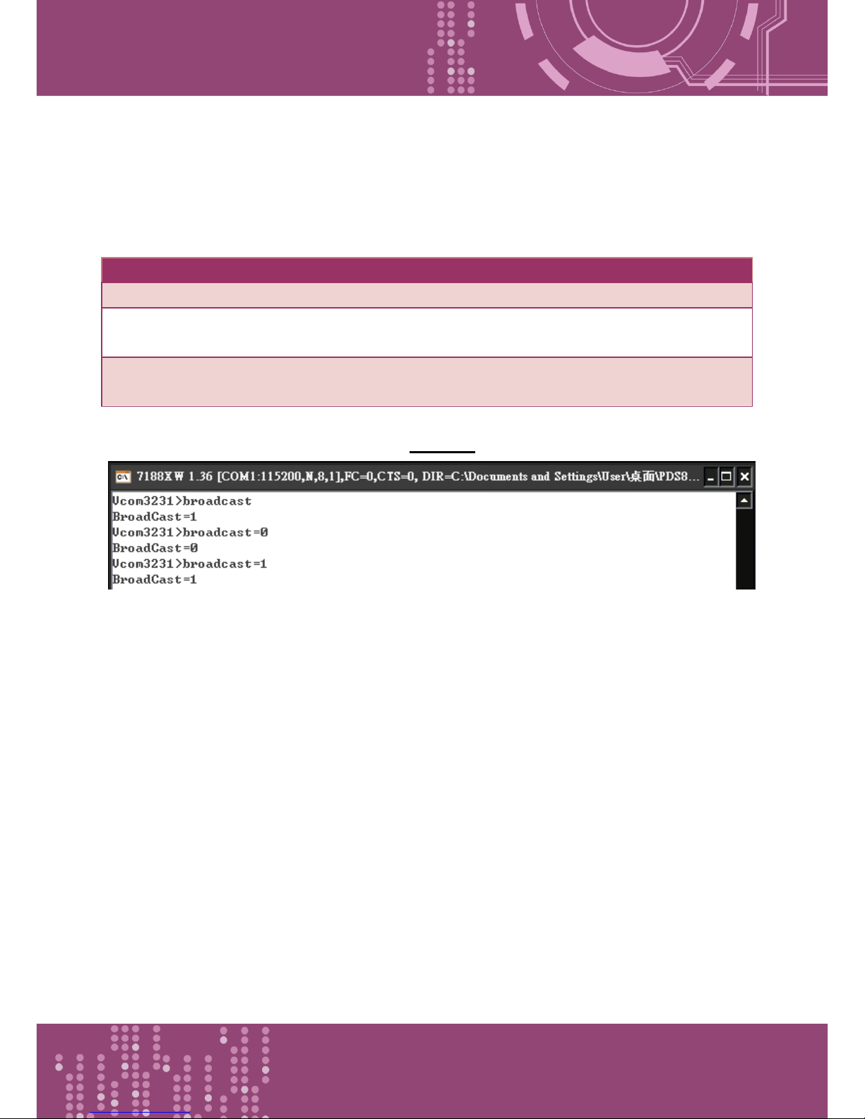
Programmable Device Server with I/O Expansion Slot(s)
PDS-8x1 Series User Manual, Version 1.1.2, Apr. 2015 - 79 -
6.3.5 Broadcast
This command is used to Enable/Disable listening broadcast packets on PDS-8x1.
Effect: Immediate
Command
Arguments
Description
Broadcast
Queries the Broadcast settings.
Broadcast
= 1
Sets Broadcast = 1.
The system is able to receive broadcast packets.
Broadcast
= 0
Sets Broadcast = 0.
The system will ignore broadcast packets.
Figure 6-3.5: The following is an example of a Broadcast configuration.
Page 80
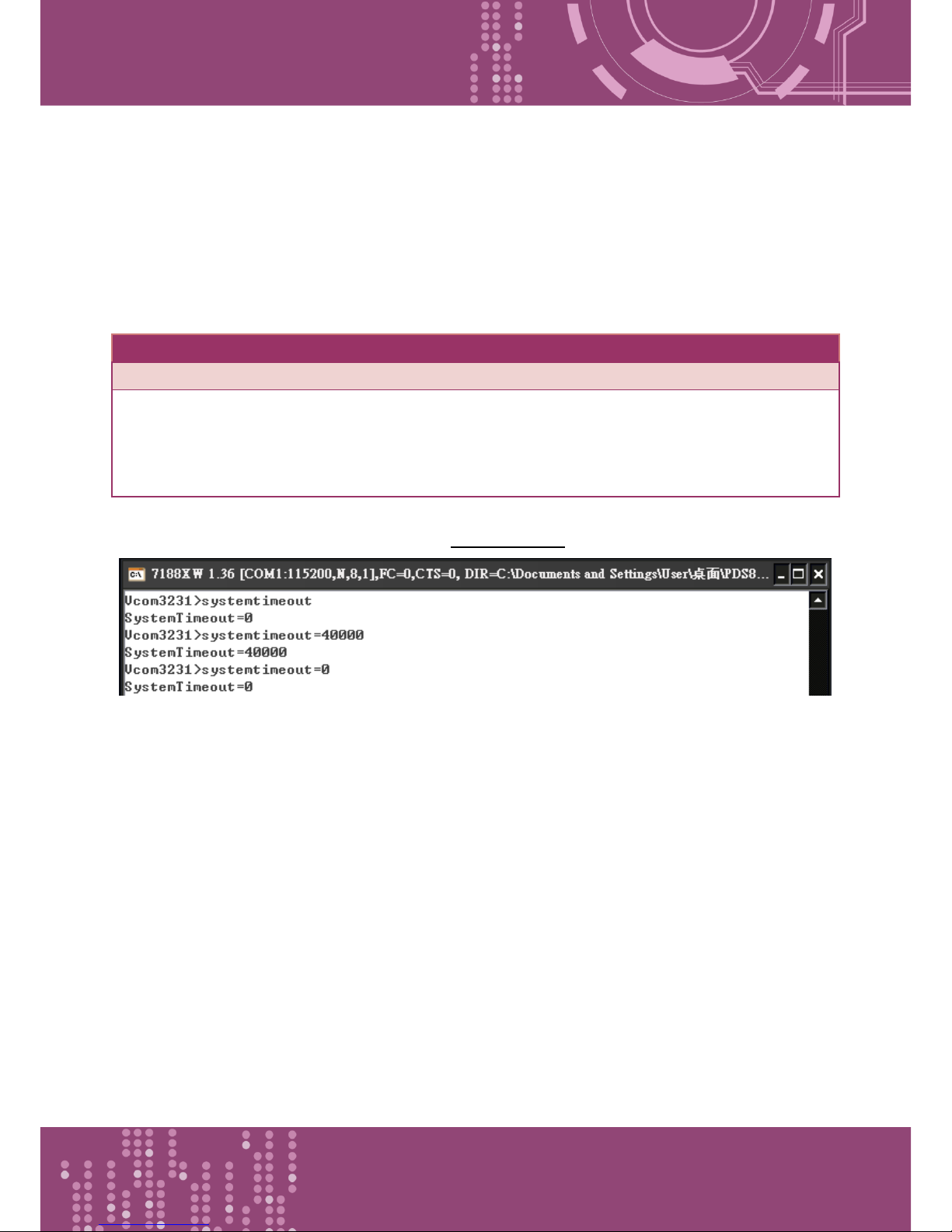
Programmable Device Server with I/O Expansion Slot(s)
PDS-8x1 Series User Manual, Version 1.1.2, Apr. 2015 - 80 -
6.3.6 SystemTimeout
This command queries or sets the system timeout value.
If the SystemTimeout is greater than zero, and the PDS-8x1 does not receive any packets from any
client for longer than the SystemTimeout period, the PDS-8x1 will reboot itself.
Effect: Immediate
Command
Arguments
Description
SystemTimeout
Queries the SystemTimeout settings.
SystemTimeout
= nnnnn
Sets the SystemTimeout. (Unit : ms)
Default factory setting is 300000 ms (= 300 seconds = 5
minutes )
Min. value is 30000 ms (= 30 seconds)
Figure 6-3.6: The following is an example of a SystemTimeout configuration.
Page 81
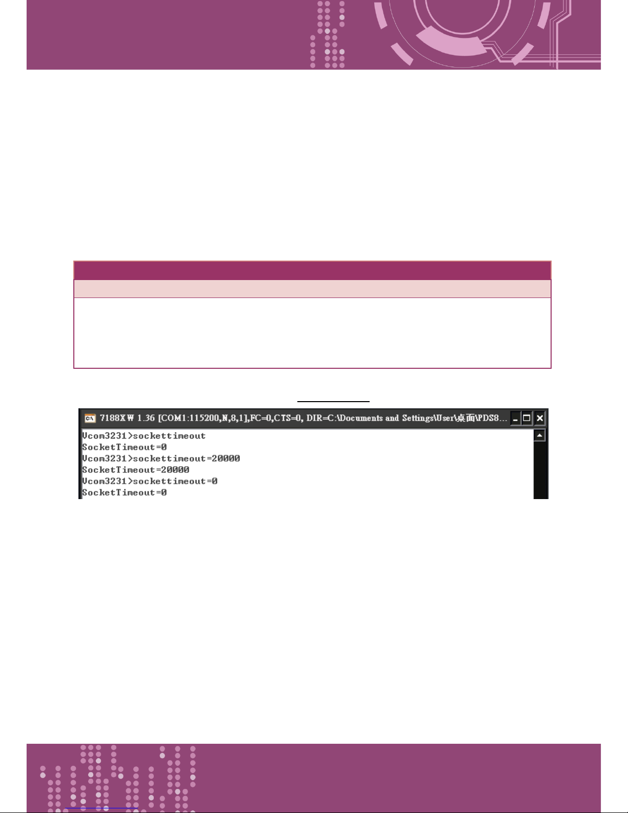
Programmable Device Server with I/O Expansion Slot(s)
PDS-8x1 Series User Manual, Version 1.1.2, Apr. 2015 - 81 -
6.3.7 SocketTimeout
This command is used to query or set the SocketTimeout parameter.
If the SocketTimeout is greater than zero, and the PDS-8x1 does not receive any data from a client
PC for longer than the SocketTimeout period, the PDS-8x1 will close the socket connection between
itself and the client PC.
Effect: Immediate
Command
Arguments
Description
SocketTimeout
Queries the SocketTimeout settings.
SocketTimeout
= nnnnn
Sets the SocketTimeout. (Unit : ms)
Default = 0 (disable)
Min. = 10000
Figure 6-3.7: The following is an example of a SocketTimeout configuration.
Page 82
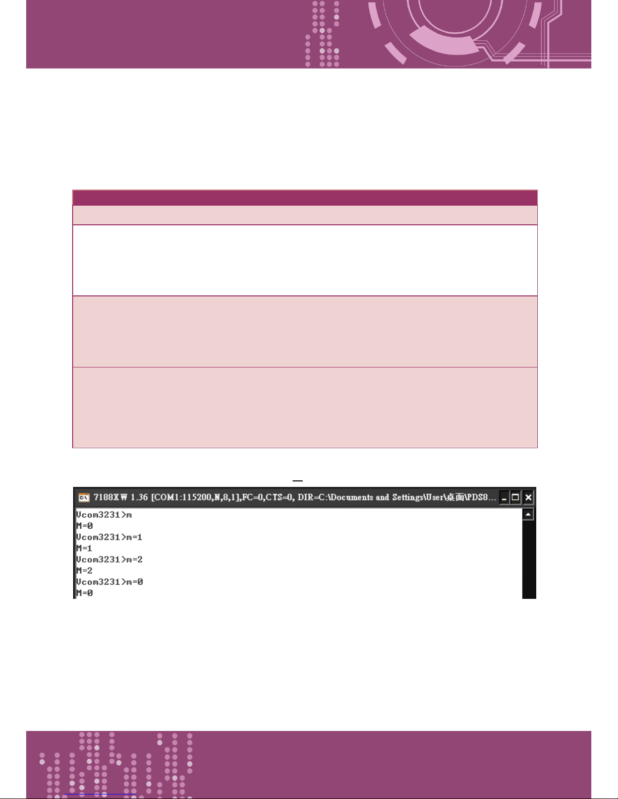
Programmable Device Server with I/O Expansion Slot(s)
PDS-8x1 Series User Manual, Version 1.1.2, Apr. 2015 - 82 -
6.3.8 M
This command is used to query or set the echo mode.
Effect: Immediate
Command
Arguments
Description
M Queries the echo mode settings.
M
= 0
Sets the Multi-echo mode to enable.
When set to multi-echo mode, the PDS-8x1 echoes data from a
device to all clients that are connected.
M
= 1
Sets the Single-echo mode to enable.
When set to single-echo mode, the PDS-8x1 echoes data from a
device to the client that requested the service.
M
=2
Sets the Half-Save Mode to enable.
If only one client connects to the PDS-8x1 controller, the
operation mode same as M0 mode; and if there are two or more
clients connecting to the PDS-8x1 controller, the operation
mode same as M1 mode.
Figure 6-3.8: The following is an example of a M configuration.
Page 83
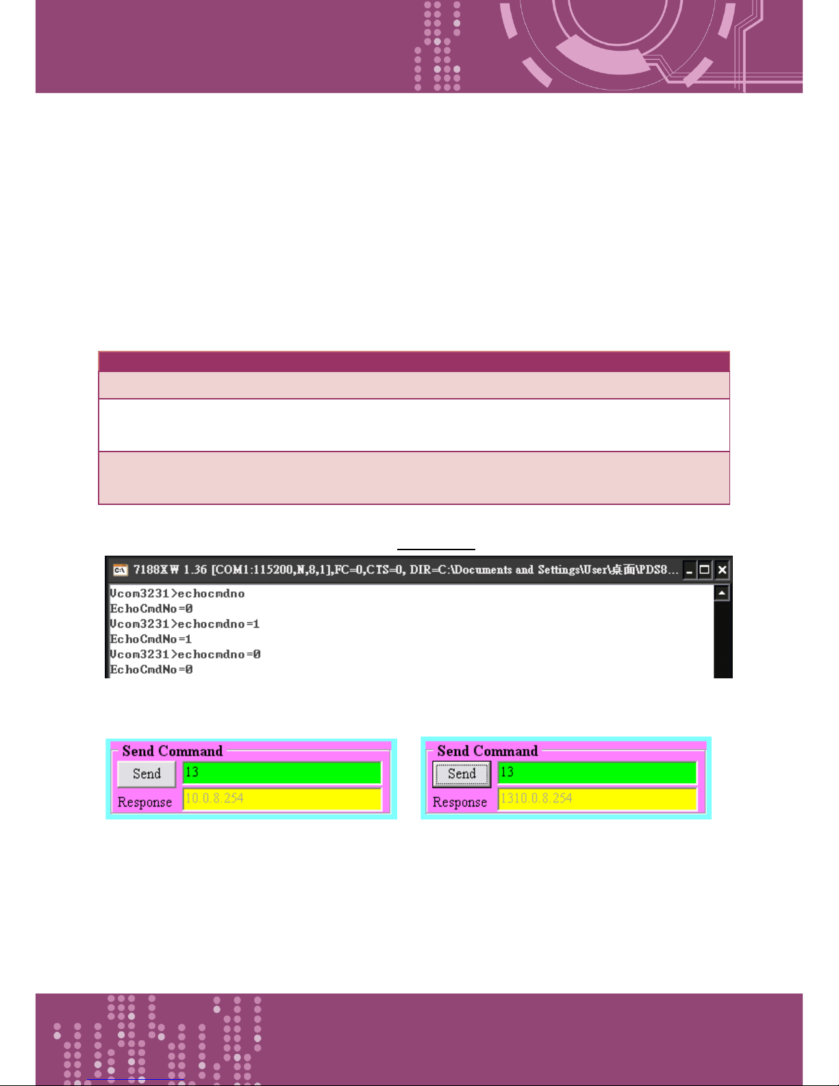
Programmable Device Server with I/O Expansion Slot(s)
PDS-8x1 Series User Manual, Version 1.1.2, Apr. 2015 - 83 -
6.3.9 EchoCmdNo
This command is used to query or set the EchoCmdNo parameter.
The EchoCmdNo parameter is used to set whether the PDS-8x1 prefixes the Virtual COM command
to the corresponding response. (Virtual COM commands are used to configure a PDS-8x1 through
TCP port 10000)
Effect: Immediate
Command
Arguments
Description
EchoCmdNo
Queries the EchoCmdNo settings.
EchoCmdNo
= 0
If EchoCmdNo = 0, a Virtual COM command number will not be
prefixed to the corresponding response.
EchoCmdNo
= 1
If EchoCmdNo = 1, a Virtual COM command number will be
prefixed to the corresponding response.
Figure 6-3.9: The following is an example of a EchoCmdNo configuration.
EchoCmdNo = 0 EchoCmdNo = 1
Page 84
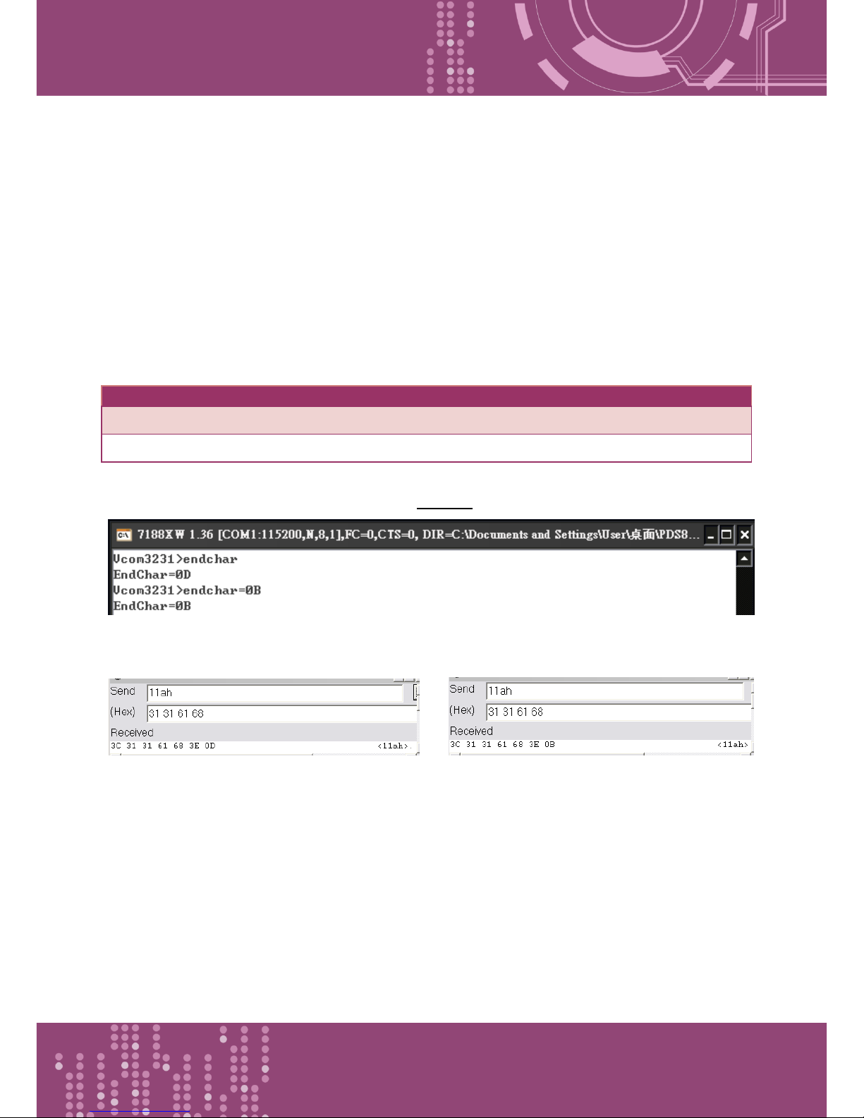
Programmable Device Server with I/O Expansion Slot(s)
PDS-8x1 Series User Manual, Version 1.1.2, Apr. 2015 - 84 -
6.3.10 EndChar
This command is used to query or set the EndChar parameter.
PDS-8x1 sends out the response string from serial port to TCP client immediately when it received a
char on the response string that matching the EndChar.
Set EndChar = 00 to disable the EndChar feature.
Effect: Immediate
Command
Arguments
Description
Endchar
Queries the endchar setting.
Endchar
= HH
Sets the endchar.
Figure 6-3.10: The following is an example of a EndChar configuration.
EndChar = 0D EndChar = 0B
Page 85
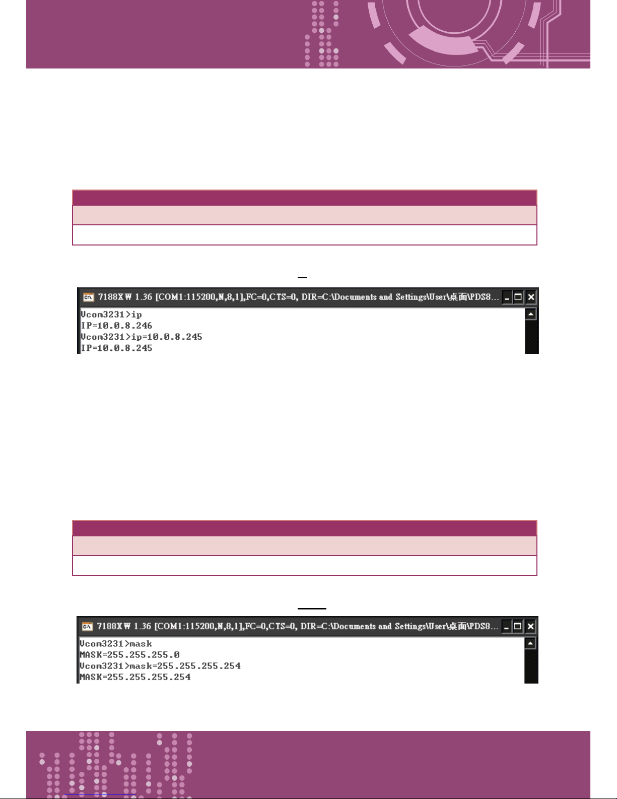
Programmable Device Server with I/O Expansion Slot(s)
PDS-8x1 Series User Manual, Version 1.1.2, Apr. 2015 - 85 -
6.3.11 IP
This command is used to query or set the IP address.
Effect: After the next reboot.
Command
Arguments
Description
IP Queries the IP address.
IP
= xxx.xxx.xxx.xxx
Sets the IP address.
Figure 6-3.11: The following is an example of a IP configuration.
6.3.12 MASK
This command is used to query or set the subnet Mask value.
Effect: After the next reboot.
Command
Arguments
Description
MASK
Queries the subnet Mask value.
MASK
= xxx.xxx.xxx.xxx
Sets the subnet Mask value.
Figure 6-3.12: The following is an example of a MASK configuration.
Page 86
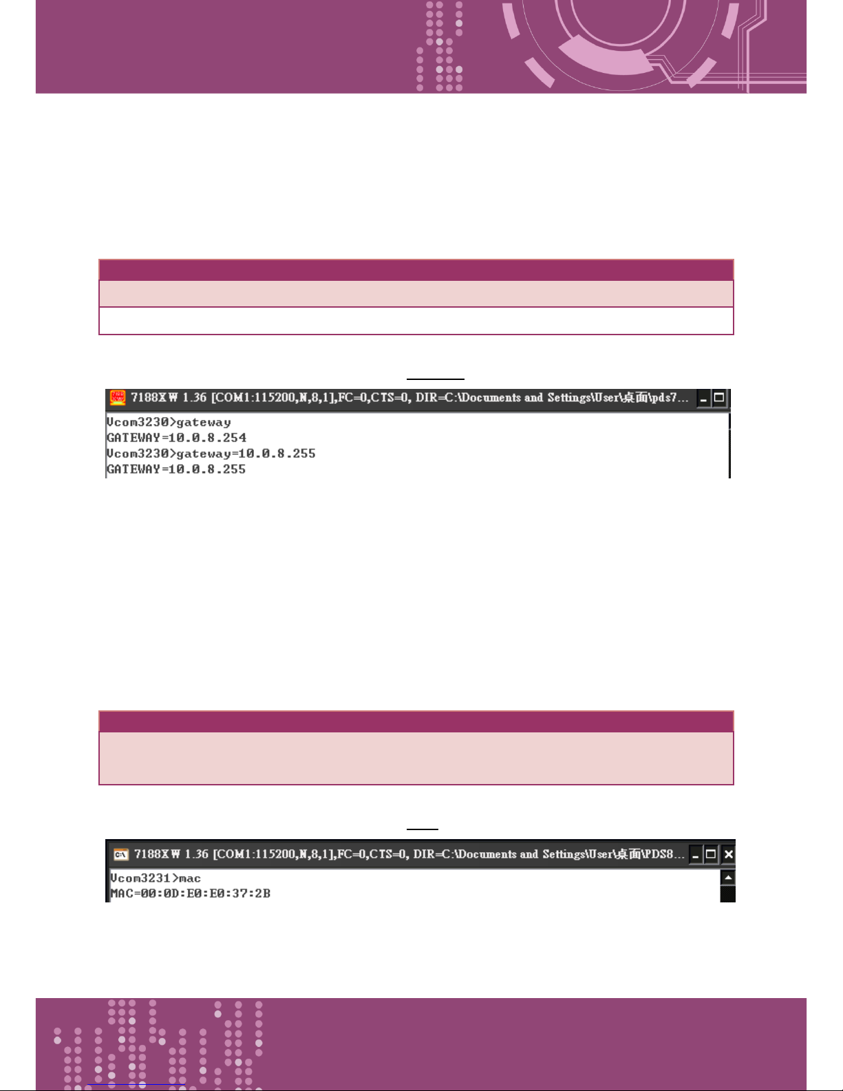
Programmable Device Server with I/O Expansion Slot(s)
PDS-8x1 Series User Manual, Version 1.1.2, Apr. 2015 - 86 -
6.3.13 GATEWAY
This command is used to query or set the outgoing Gateway address of the subnet.
Effect: After the next reboot.
Command
Arguments
Description
Gateway
Queries the subnet Gateway value.
Gateway
= xxx.xxx.xxx.xxx
Sets the subnet Gateway value.
Figure 6-3.13: The following is an example of a Gateway configuration.
6.3.14 MAC
This command is used to query the MAC address.
Effect: Setting the address is not allowed.
Command
Arguments
Description
MAC
Queries the MAC address.( Setting the address is not
allowed)
Figure 6-3.14: The following is an example of a MAC configuration.
Page 87
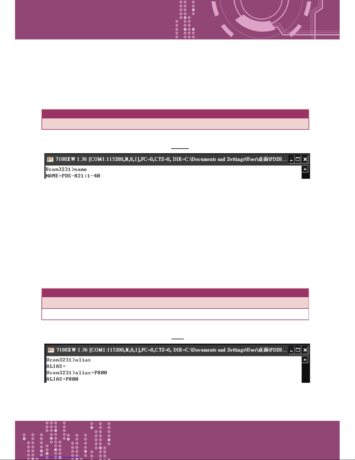
Programmable Device Server with I/O Expansion Slot(s)
PDS-8x1 Series User Manual, Version 1.1.2, Apr. 2015 - 87 -
6.3.15 NAME
This command is used to query the name of a PDS-8x1 controller.
Effect: Setting the address is not allowed.
Command
Arguments
Description
NAME
Queries the name of a PDS-8x1 controller.
Figure 6-3.15: The following is an example of a NAME configuration.
6.3.16 ALIAS
This command is used to query or set the alias of a PDS-8x1. The maximum character length of PDS-
8x1 alias name is 16 bytes.
Effect: Immediate
Command
Arguments
Description
alias
Queries the alias.
alias
= xxxx
Sets the alias of a PDS-8x1 controller to “xxxx”.
Figure 6-3.16: The following is an example of a alias configuration.
Page 88
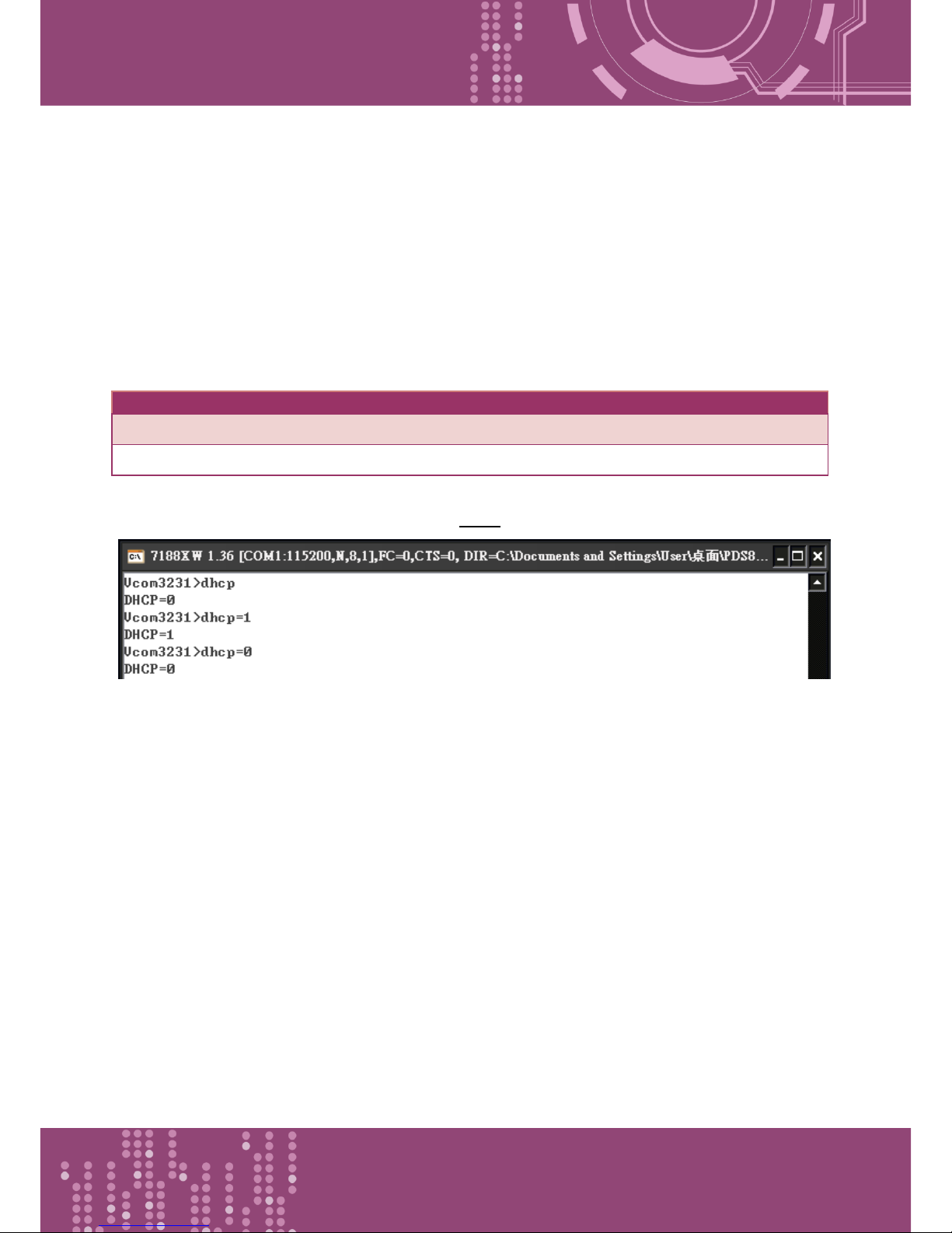
Programmable Device Server with I/O Expansion Slot(s)
PDS-8x1 Series User Manual, Version 1.1.2, Apr. 2015 - 88 -
6.3.17 DHCP
This command is used to set the DHCP client to either enabled or disabled.
DHCP function will get a dynamic IP address setting for PDS-8x1 automatically. Thus it's
recommended to disable DHCP function and use a static IP address setting. This prevents you to
configure virtual COM mappings again and again.
Effect: Immediate
Command
Arguments
Description
DHCP
= 0
Disables the DHCP client.
DHCP
= 1
Enables the DHCP client.
Figure 6-3.17: The following is an example of a DHCP configuration.
Page 89
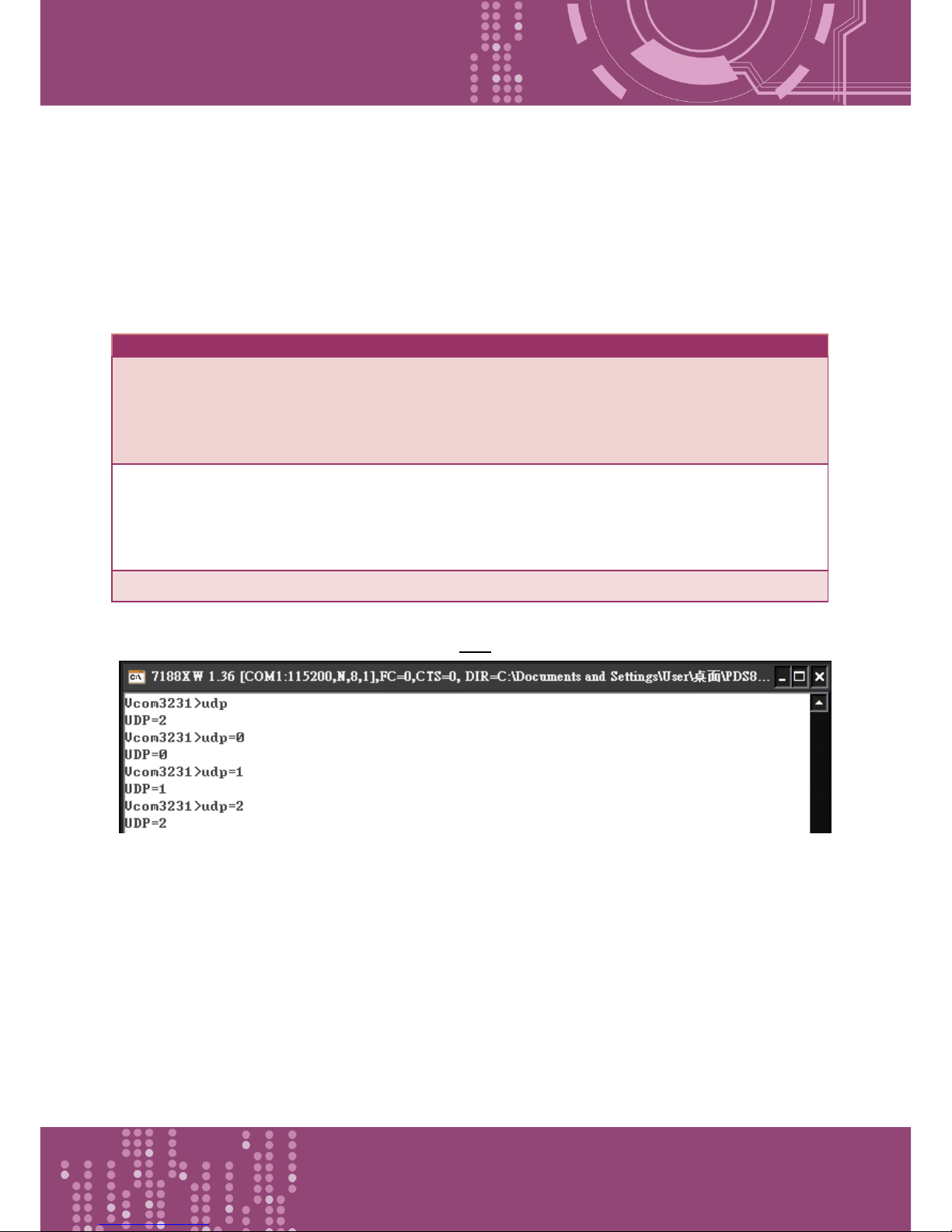
Programmable Device Server with I/O Expansion Slot(s)
PDS-8x1 Series User Manual, Version 1.1.2, Apr. 2015 - 89 -
6.3.18 UDP
This command is used to configure the UDP Search function.
UDP is used to set the action mode for when a PDS-8x1 receives a UDP search command.
Effect: Immediate
Command
Arguments
Description
UDP
= 0
Rejects UDP search commands.
The PDS-8x1 will not reply to the UDP search command, and can
not be searched again.
UDP
= 1
Replies to UDP search commands.
The PDS-8x1 controller will reply to the UDP search command,
and can be searched.
UDP
= 2
Replies to UDP search commands till a client is connected.
Figure 6-3.18: The following is an example of a UDP configuration.
Page 90
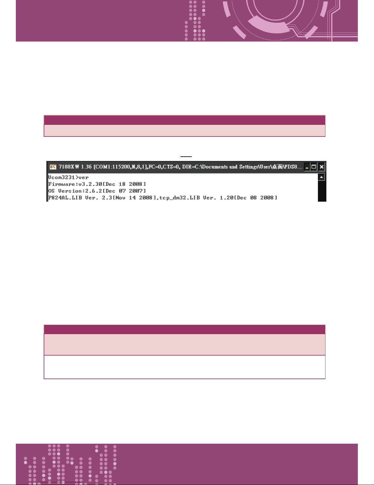
Programmable Device Server with I/O Expansion Slot(s)
PDS-8x1 Series User Manual, Version 1.1.2, Apr. 2015 - 90 -
6.3.19 VER
This command is used to query the version information for a PDS-8x1.
Effect: Setting the version information is not allowed.
Command
Arguments
Description
VER
Queries the version information.
Figure 6-3.19: The following is an example of a VER configuration.
6.3.20 SAVE
This command is used to set the PDS-8x1 to backup or no-backup “autoexec.bat” and “vcom.ini”
files when using “load” command.
Effect: Immediate
Command
Arguments
Description
save
= 1
When the “load” command is used, backup copies of the
"autoexec.bat" and "vcom.ini" files will be saved.
save
= 0
(Default)
When the “load” command is used, backup copies of the
"autoexec.bat" and "vcom.ini" files will NOT be saved.
Refer to Figures 6-3.20 and 6-3.21 for detail illustrations.
Page 91
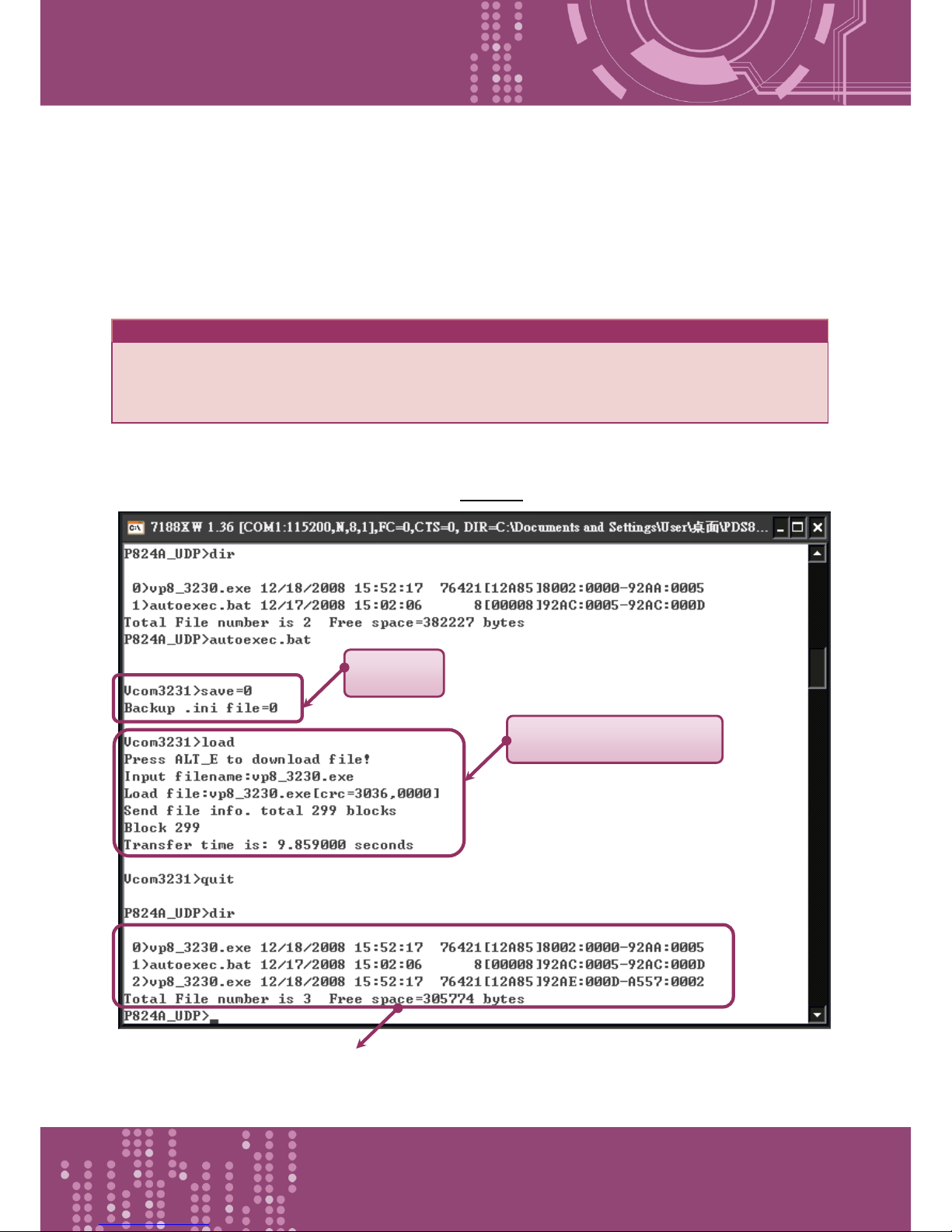
Programmable Device Server with I/O Expansion Slot(s)
PDS-8x1 Series User Manual, Version 1.1.2, Apr. 2015 - 91 -
6.3.21 LOAD
This command is used to loads file to the built-in flash disk on PDS-8x1. It should be used to update
firmware only.
Effect: Immediate
Command
Arguments
Description
load
The command is coordinated with the MiniOS7 “load” command
and can be used to renew the “vcom3230.exe,” “vcom.ini” or
“autoexec.bat” file(s).
※ “Load” is not a Telnet command.
Figure 6-3.20: The following is an example of a Save = 0 configuration.
※When save = 0, the system doesn’t back up the "autoexec.bat" and "vcom.ini" files to memory,
and doesn’t clear the flash disk. It only loads the file that is selected specified.
Save=0
Load vp8_3230.exe
Page 92
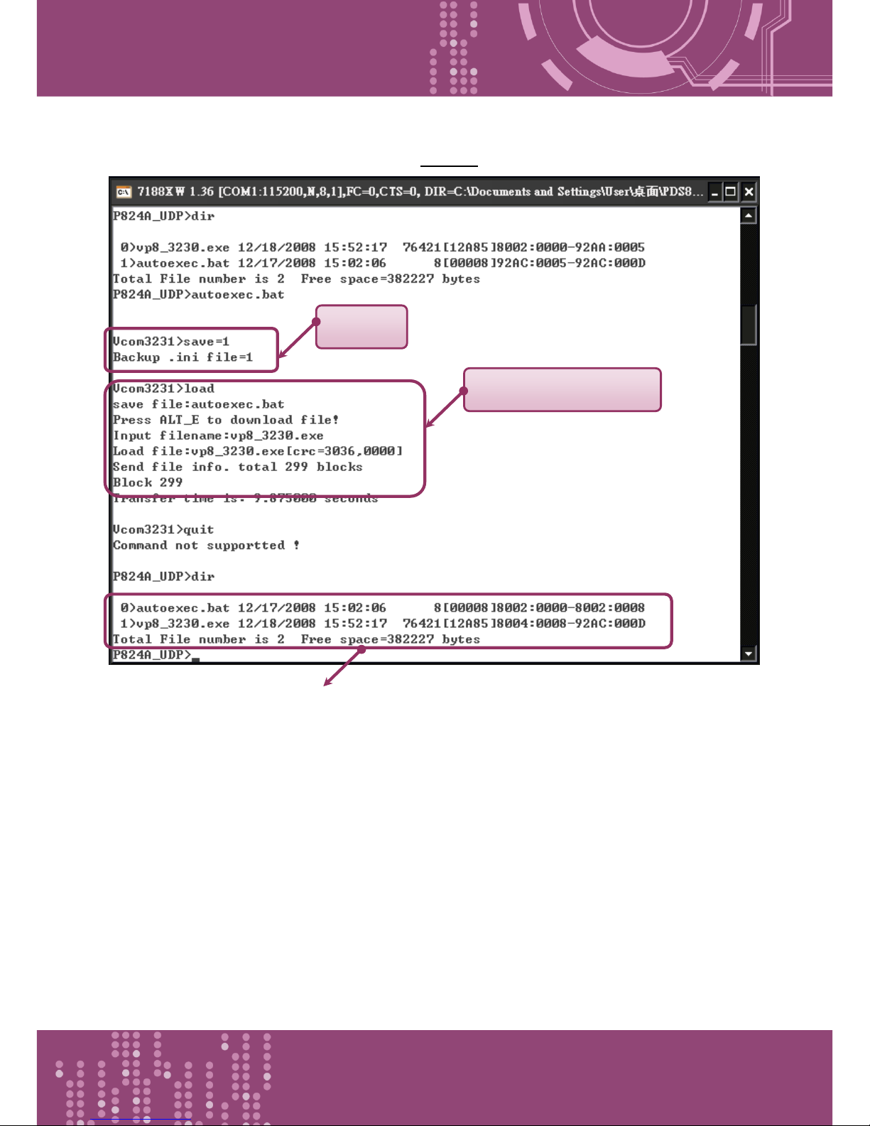
Programmable Device Server with I/O Expansion Slot(s)
PDS-8x1 Series User Manual, Version 1.1.2, Apr. 2015 - 92 -
Figure 6-3.21: The following is an example of a Save = 1 configuration.
※ When save = 1, system will back up the "autoexec.bat" and "vcom.ini" files to memory first,
clear all files in the flash disk, and then load the "autoexec.bat" and "vcom.ini" files from
memory and run the “load” command to load the specified file(s).
Save=1
Load vp8_3230.exe
Page 93
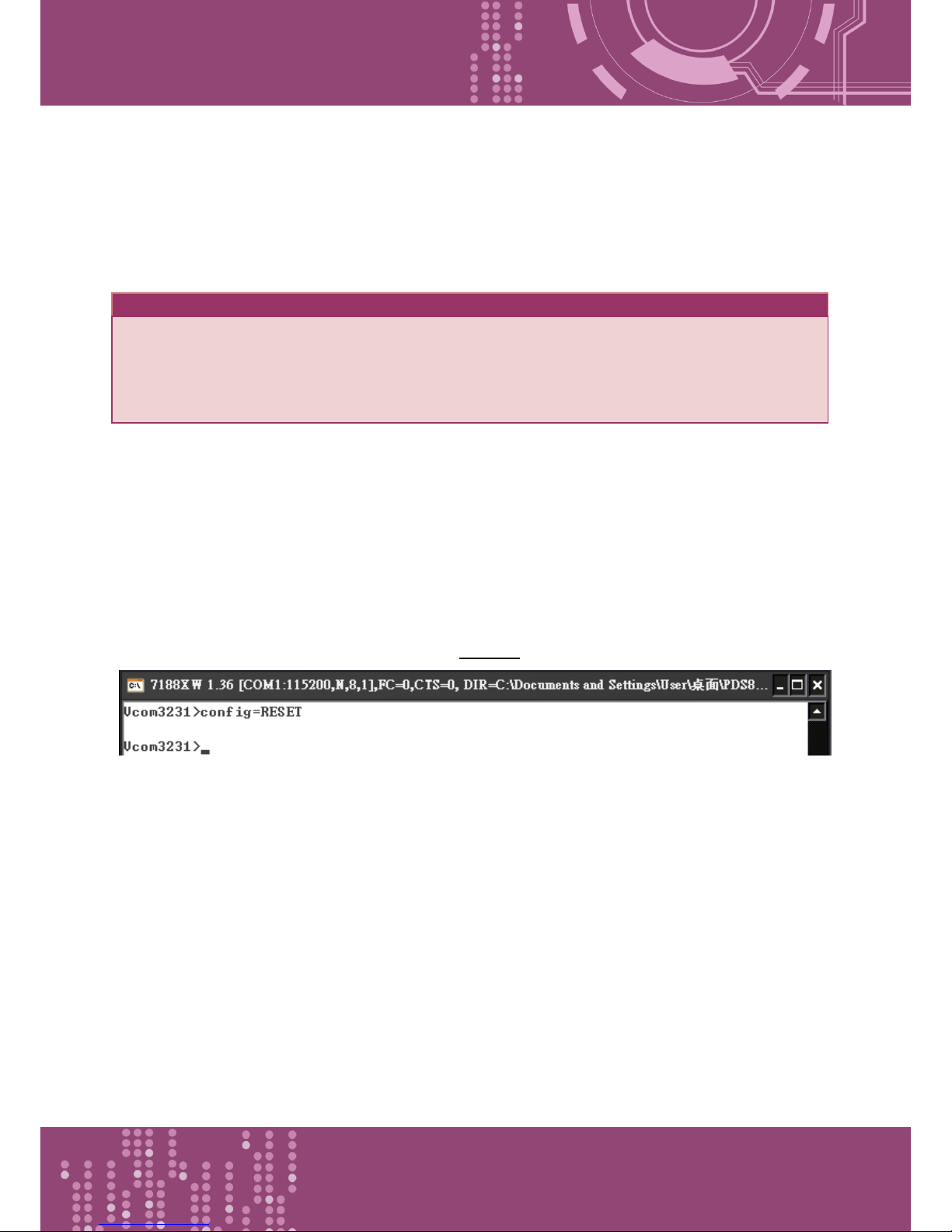
Programmable Device Server with I/O Expansion Slot(s)
PDS-8x1 Series User Manual, Version 1.1.2, Apr. 2015 - 93 -
6.3.22 CONFIG
This command is used to clear the settings in the EEPROM.
Effect: Immediate
Command
Arguments
Description
config
= RESET
Clears the settings in the EEPROM.
After reboot, the firmware will use the new (default) settings on
EEPROM.
Note: "RESET" MUST be in capital letters.
※When “Config=RESET” is used, the Password, Alias and IPFILTER settings will also be cleared,
but the IP/MASK/GATEWAY addresses will not.
※The SystemTimeout setting is also cleared to 0 by the "config=RESET" command, you have to
configure the SystemTimeout value again. The default factory setting of SystemTimeout value
should be 300000 ms (= 300 seconds).
Figure 6-3.22: The following is an example of a CONFIG configuration.
Page 94
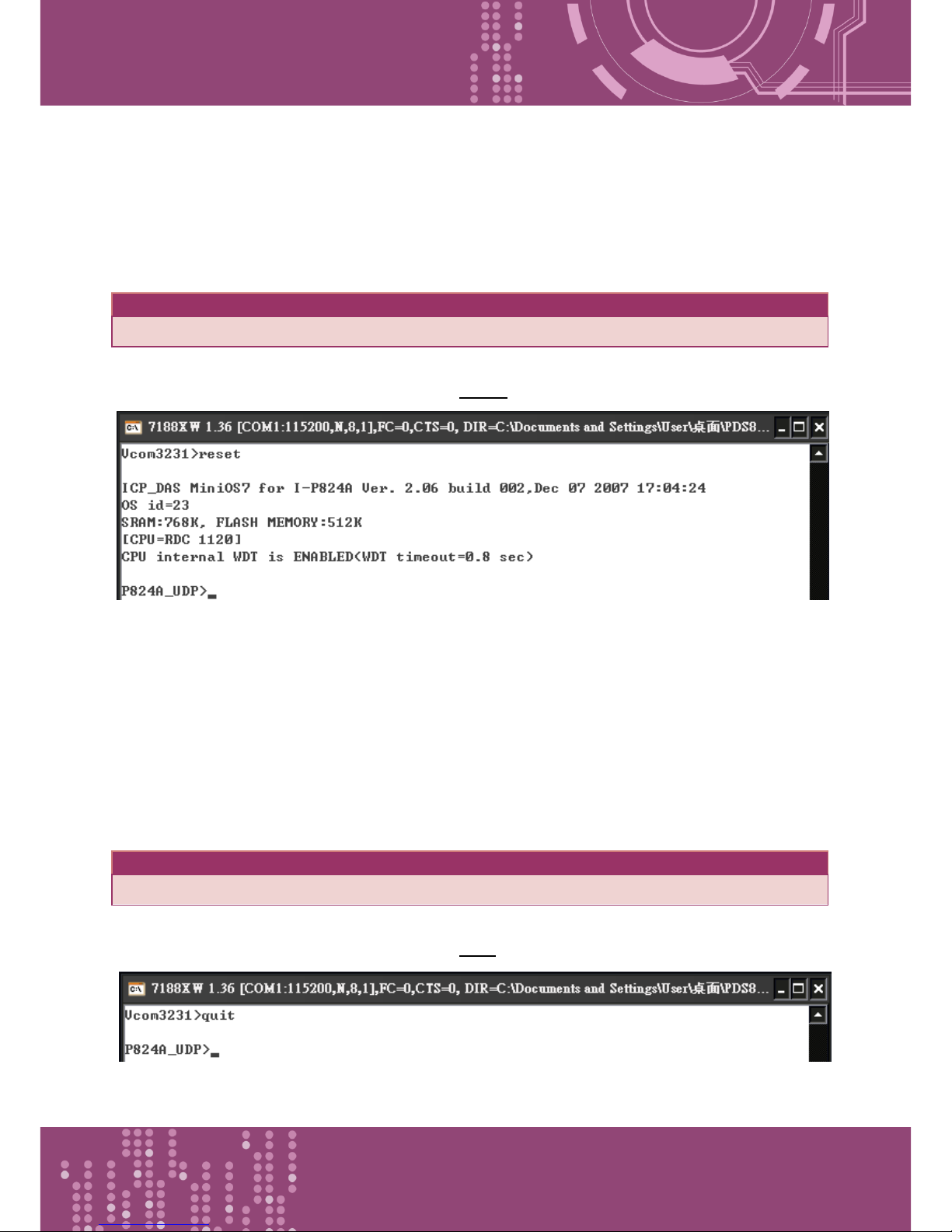
Programmable Device Server with I/O Expansion Slot(s)
PDS-8x1 Series User Manual, Version 1.1.2, Apr. 2015 - 94 -
6.3.23 RESET
This command is used to reboot the PDS-8x1 controller.
Effect: Immediate
Command
Arguments
Description
reset
Reboot the PDS-8x1 controller.
Figure 6-3.23: The following is an example of a RESET configuration.
6.3.24 QUIT
This command is used to stop and quit the firmware of PDS-8x1 controller.
Effect: Immediate
Command
Arguments
Description
quit
Quits the firmware.
Figure 6-3.24: The following is an example of a Quit configuration.
Page 95
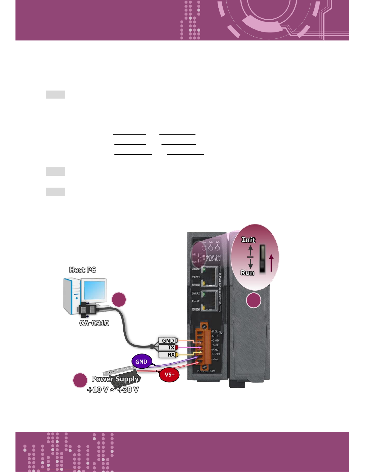
Programmable Device Server with I/O Expansion Slot(s)
PDS-8x1 Series User Manual, Version 1.1.2, Apr. 2015 - 95 -
Appendix A: Linking to a Development PC
Step 1: Connect the download-cable (CA0910), between the PDS-8x1 controller and COM 1 of the
development PC.
1-1: Connect the connector of CA-0910 download cable to your host computer.
1-2: Wire the CA-0910 to PDS-8x1 controller, as follows:
Connect the CA-0910.TX with PDS-8x1.TxD
Connect the CA-0910.RX with PDS-8x1.RxD
Connect the CA-0910.GND with PDS-8x1.GND
Step 2: Set the Init/Run Switch in “Init Mode” position.
Step 3: Supply +24 VDC (+10 ~ +30 VDC) power to the PDS-8x1 controller.
Refer to below illustration for how to perform the above procedure.
1
2
3
Page 96
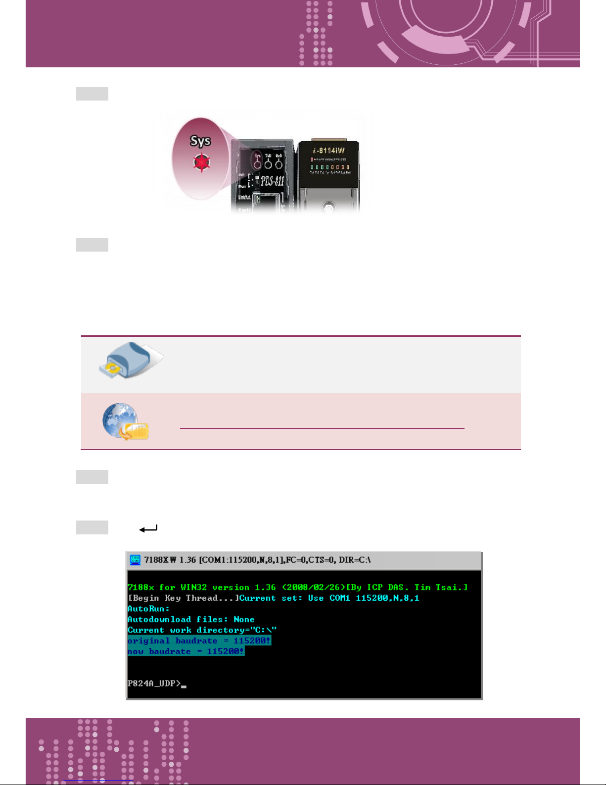
Programmable Device Server with I/O Expansion Slot(s)
PDS-8x1 Series User Manual, Version 1.1.2, Apr. 2015 - 96 -
Step 4: Verify that the System LED indicator is flashing on the PDS-8x1 controller.
Step 5: Unzip the “7188XW_yyyymmdd.zip” file on the PC.
The “7188XW_yyyymmdd.zip”can be obtained from either the companion CD-ROM, the ICP DAS FTP site,
or the ICP DAS web site. The location of the install files on the CD and the download addresses are shown
below:
CD:\\ NAPDOS\MiniOS7\Utility\
http://ftp.icpdas.com/pub/cd/8000cd/napdos/minios7/utility/
Step 6: Execute 7188XW.EXE/C#, and change the Baud Rate to 115200 bps, N81. “/C#” is the COM
Port of the development PC.
Step 7: Press [ Enter] twice on the development PC.
Page 97
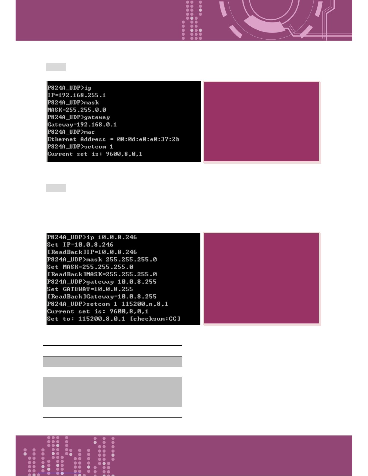
Programmable Device Server with I/O Expansion Slot(s)
PDS-8x1 Series User Manual, Version 1.1.2, Apr. 2015 - 97 -
Step 8: Read the configuration of the PDS-8x1 (The following is a default value).
Step 9: The configuration of the PDS-8x1 as follows can be changed.
Please setting for with your PC same network region IP/Mask/Gateway addresses.
This example: 10.0.8.246/255.255.255.0/10.0.8.255
Table A-1: “setcom” parameters are as follows.
Port
1
Baud Rate
2 ~ 921600
Data Bit
7, 8: for COM 1
Parity
N, n : None parity
E, e : Even parity
O, o : Odd parity
Stop Bit
1: for COM 1
Settings configuration command
ip [new ip]
mask [new mask]
gateway [new gateway]
mac [new mac]
setcom port (refer to Table A-1)
[baud][data_bit][parity][stop_bit]
Read configuration command
Ip
Mask
Gateway
Mac
setcom port
Page 98
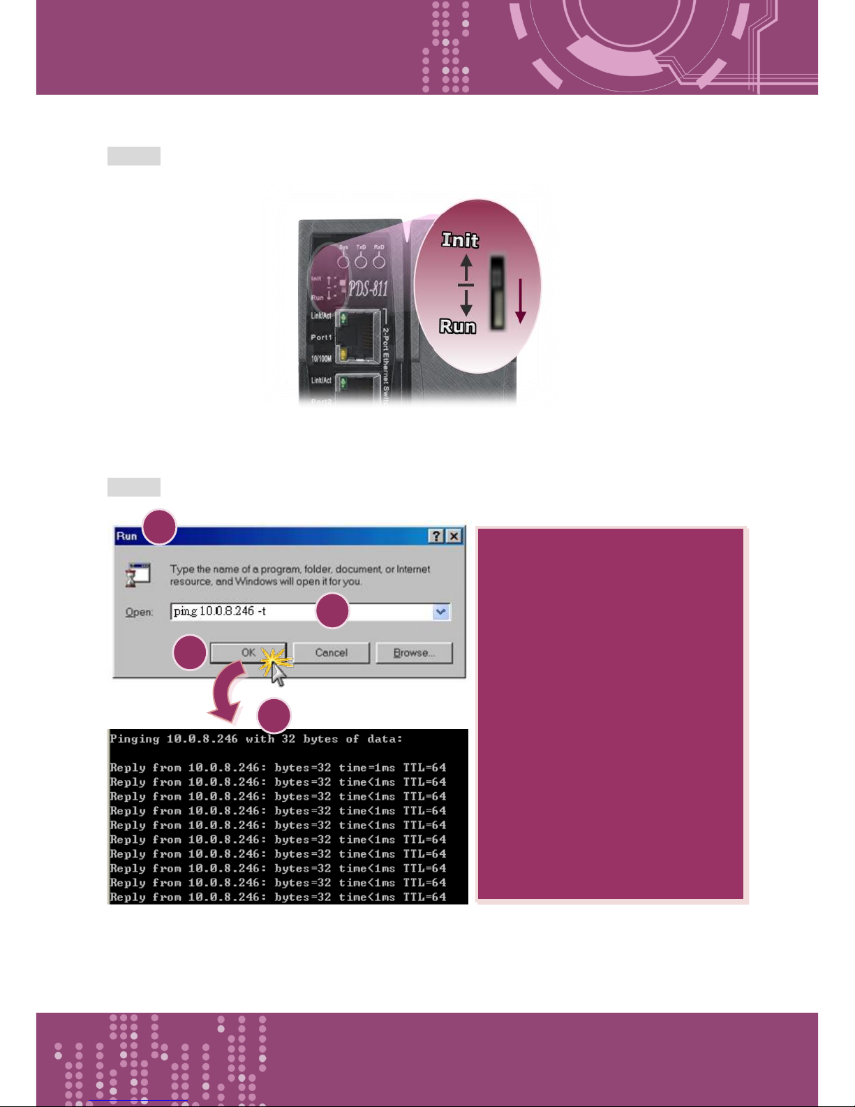
Programmable Device Server with I/O Expansion Slot(s)
PDS-8x1 Series User Manual, Version 1.1.2, Apr. 2015 - 98 -
Step 10: Set the Init/Run Switch in “Run Mode” position, and then power-on reboot the PDS-8x1
controller.
Step 11: Execute ping you setting IP (Example: ping 10.0.8.246 –t) using a run command.
1
3
2
Follow the procedure described
below:
1. Click the “Start” button and then
click “Run” to open the “Run
Command” dialog box.
2. In the “Run Command” dialog
box, type “pin 10.0.8.246 -t” in
the “Open:” field.
3. Click the “OK” button to open a
Command Prompt window.
4. The ping results should be smooth
and continuous
4
Page 99

Programmable Device Server with I/O Expansion Slot(s)
PDS-8x1 Series User Manual, Version 1.1.2, Apr. 2015 - 99 -
In general, if the host PC can ping the PDS-8x1 controller smoothly and continuously, all other
software and drivers for the PDS-8x1 controller will operate correctly. Therefore, users should
ensure that the development PC is able to ping the PDS-8x1 controller smoothly before any further
testing is carried out.
Note:
1. 192.168.255.1 is the default IP of the PDS-8x1 controller. The IP address can be changed
using the instructions in step 8.
2. If the PDS-8x1 cannot be successfully pinged from the PC, refer to step 8 to change the
configuration of the PDS-8x1 controller. (The mask and gateway addresses of PDS-8x1
controller and the PC should make the network definition.)
3. The MAC address of the PDS-8x1 controller should be unique on the same network.
Refer to step 8 for details of how to change the MAC address of the PDS-8x1 controller.
4. Each PDS-8x1 MAC address is unique in the default shipping.
Page 100

Programmable Device Server with I/O Expansion Slot(s)
PDS-8x1 Series User Manual, Version 1.1.2, Apr. 2015 - 100 -
Appendix B: Glossary
1. ARP (Address Resolution Protocol)
The Address Resolution Protocol (ARP) is a telecommunication protocol that is used to convert an
IP address to a physical address, such as an Ethernet address.
Consider two machines A and B that share the same physical network. Each has an assigned IP
address IPA and IPB, and a MAC address, MACA and MACB. The goal is to devise a low-level software
application that hides the MAC addresses and allows higher-level programs to work only with the IP
addresses. Ultimately, however, communication must be carried out by the physical networks using
whatever MAC address scheme the hardware supplies.
Suppose machine A wants to send a packet to machine B across a physical network to which they
are both attached, but A only has the Internet address for B, IPB. The question arises: how does A
map that address to the MAC address for B, MACB?
ARP provides a method of dynamically mapping 32-bit IP address to the corresponding 48-bit MAC
address. The term dynamic is used since the mapping is performed automatically and is normally
not a concern for either the application user or the system administrator.
2. Clients and Servers
The client-server paradigm uses the direction of initiation to categorize whether a program is a
client or server. In general, an application that initiates peer-to-peer communication is called a
client. End users usually invoke client programs when they use network services.
By comparison, a server is any program that waits for incoming requests from a client program. The
server receives a request from a client, performs the necessary actions and returns the result to the
client.
 Loading...